
Related Manuals for BXB Electronics EDC-2051

Summary of Contents for BXB Electronics EDC-2051
- Page 1 EDC-2051 Conference Main Control Unit Instruction Manual Firmware: Ver.1.9.1 Date: Feb. 2020...
-
Page 2: Table Of Contents
EDC-2051 Instruction Manual Contents Safety Instruction …...………………………………..…..……..…..……....2 Product Features ……..……………………………….………….…….…….……...…...3 System Connection ……...………………………………..….…….…….……..…..4 Physical Description Front View....…………………….….….…….…….…...….…….……..…...5 Rear View .…………………..…….…….…….……..….……....…..…..6 Basic Operation Turn On the Unit.......…….…….…….…….…….……....…..…..7 Using the Front Panel LCD..…...…….….…….…….…….…….……..….…..8 Advanced Operation Check the MIC ID...……….……….…….…….…….…….……....…..…..9 Set the Meeting Mode....…….…….…….…….……......…..10 Set the Open-Mic Qty....…..…….…….…….…….……....…..…..11... -
Page 3: Safety Instruction
EDC-2051 Instruction Manual Safety Instruction 01. Read the instruction manual carefully before installing and using this unit. 02. Follow the instructions and be aware of warning indications. 03. Please do not use any spare parts without the recommendation of your dealer. -
Page 4: Product Features
EDC-2051 Instruction Manual Product Features Conference Main Control Unit ● Quick installation & easy maintenance via CAT5E cables. ● Equipped 4-chain RJ45 ports: each port enables the max. of 15 units; the total is 50 units. Via BXB extension power supply, it enables the max. of 265-unit connection. -
Page 5: System Connection
Please make sure the power is off before unplugging any unit. Re-start the unit after the installation has been completed. EDC-2011/2012 Table-top Chairman/Delegate Unit CAT5E (loop distribution) SW-003 RJ45 Distributor EDC-2051 Conference Main Control Unit Audio output pin (XLR) 1: Ground 2: Sound(Aux) 3: Empty Aux Output (Unbalanced) IOIOI Pin... -
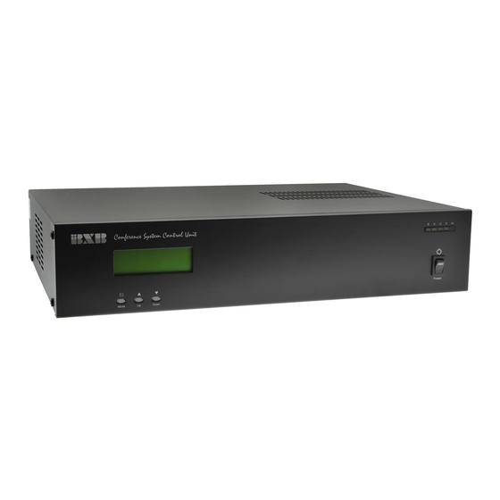
Page 6: Physical Description
EDC-2051 Instruction Manual Physical Description Front View 1. Power switch 2. Conference function control MODE Mode-selection Gain parameter setting/volume up DOWN Reduce parameter setting/volume down 3. Volume output LED indicator 4. 4 x 20 LCD screen... -
Page 7: Rear View
EDC-2051 Instruction Manual Physical Description Rear View 1. AUX Output (Unbalance, XLR connector) Pin 1: Ground Pin 2: Sound (Aux) Pin 3: Empty 2. Volume knob for the built-in speaker of the microphone unit 3. LINK 1~4: microphone unit port (RJ45) 4. -
Page 8: Basic Operation
LED indicator of the malfunctioned microphone units will flash. It indicates the failed connection. In this case, the power of EDC-2051 should be switched off and then switched on again after checking the microphone connection. If the red LED indicator of microphones is constantly on for more than 5 seconds, the connection is normal. -
Page 9: Using The Front Panel Lcd
EDC-2051 Instruction Manual Basic Operation Using the Front Panel LCD 1) NO: the ID number of the operating microphone; 3 sets of ID numbers displayed per page. Chairman MIC: *01~*10 Delegate MIC: 001~255 2) MODE: Normal: Normal Mode Override: Override Mode Chairman: Chairman Mode 3) OPEN-MIC: the number of speaking microphones at the same time;... -
Page 10: Advanced Operation
When the conference microphone is in use, the red indicator ring on the microphone will be on constantly. Meanwhile, its ID number will be displayed on the LCD screen of EDC-2051. Max. of 3-set ID numbers can be shown on the main menu. -
Page 11: Set The Meeting Mode
EDC-2051 Instruction Manual Advanced Operation Set the Meeting Mode ❏ Press MODE button and move the “◘” icon to “2. MODE”. Meanwhile, the “Normal” item is flashing. Just press “UP▲” or “DOWN▼” button to change the conference mode. ❏ Following are all the conference modes offered: ※... -
Page 12: Set The Open-Mic Qty
EDC-2051 Instruction Manual Advanced Operation Set the Open-Mic Qty ❏ ALL Mic/1-9 delegate microphones turn on at the same time. ❏ Press MODE button and then move” ◘” to “OPEN-MIC”, Meanwhile, “03 Mic” item will flash. Just press “UP▲” or “DOWN▼” button to change the Open- Mic quantity. -
Page 13: Set The Mic Auto-Off Time
EDC-2051 Instruction Manual Advanced Operation Set the MIC Auto-OFF Time ❏ Delegate unit will be automatically off after receiving no sound for 30/45 sec. The delegate can also switch off the speaking button manually. ❏ Press MODE button and move “◘” to “AUTO-OFF”. Meanwhile, “30 Sec” item will be flashing. -
Page 14: Volume Setting
/recording output. ❏ If EDC-2051 doesn’t detect any action, it would go back to the main menu. The current setting would be also saved automatically. You don’t need to press any button for saving and exiting. -
Page 15: Microphone Spk Setting
With the "SPK_OFF“ mode, the audio output of the earphone and recording still work normally. ❏ If EDC-2051 doesn’t detect any action, it would go back to the main menu. The current setting would be also saved automatically. You don’t need to press any button for saving and exiting. -
Page 16: Microphone Unit
EDC-2051 Instruction Manual Microphone Unit EDC-2011 Table-top Chairman Unit 2. Built-in 2.5” loudspeaker 1. Gooseneck MIC plug (DIN TYPE) 3. Control button with indicator light 4. Speaking button with indicator light 6. Earphone plug (Φ 3.5 stereo) 5. Earphone volume control 7. -
Page 17: Edc-2012 Table-Top Delegate Unit
EDC-2051 Instruction Manual Microphone Unit EDC-2012 Table-top Delegate Unit 2. Built-in 2.5” loudspeaker 1. Gooseneck MIC plug (DIN TYPE) 3. Speaking button with indicator light 4. Earphone volume control 5. Earphone plug (Φ3.5 stereo) 6. Recording plug (Φ3.5 stereo) 7. DIP switch for MIC ID setting 8. -
Page 18: Appendix
Please refer to the table below for Chairman/Delegate DIP Switch setting. EDC-2011 chairman ID range→ *01~*10 EDC-2012 delegate ID range→ 1~255 Note: When switching to the number out of the range, the microphone’s indicator light will flash as EDC-2051 is turned on. Protocol Setting Type RS-232... -
Page 19: Connected Qty. Of Microphone Units
EDC-2051 Instruction Manual Appendix Connected Qty. of Microphone Units Total connected microphone units of the MCU: Cable length of 120M each circuit Suggested qty. of connected units of 4 circuits Notice: ❏ Within 100M of each circuit, the maximum of connected microphone units is 15. - Page 20 BXB Electronics Co., Ltd. 6F-1, No.288-5, Xinya Rd., Qianzhen Dist., Kaohsiung City 80673, Taiwan TEL +886(7)9703838 FAX +886(7)9703883 www.bxb.tw/en © 2020 BXB Electronics Co., Ltd.
Need help?
Do you have a question about the EDC-2051 and is the answer not in the manual?
Questions and answers