Table of Contents
Advertisement
Quick Links
HEAD OFFICE
VCCE Office Park
170 Peter Brown Dr
Pietermaritzburg
3201 South Africa
Tel: + 27 33 260 2700
Fax: + 27 33 260 2701
PO Box 4099
W illowton Hub
3200 South Africa
NORTECH INTERNATIONAL (PTY) LTD
All rights reserved
Copyright © 2016
Document Number: 307UM0100_01
Date of Issue: May 2016
This document is for informa�on only and unless otherwise indicated, is not to form part of any contract. In
accordance with the manufacturer's policy of con�nually updating and improving design, specifications
FACTORY
32a W iganthorpe Rd
W illowton
Pietermaritzburg
3201 South Africa
Tel: + 27 33 345 3456
Fax: + 27 33 394 6449
www.nortech.co.za
info@nortech.co.za
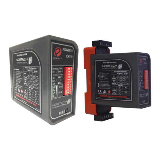
Single Channel parking Detector
User Manual
contained herein are subject to altera�on without no�ce.
Nortech International (Pty) Ltd.
Reg. No. 1998/010951/07
PD17x
Advertisement
Table of Contents


Need help?
Do you have a question about the PD17 Series and is the answer not in the manual?
Questions and answers