Table of Contents
Advertisement
Quick Links
The detectors comply with EN 54-5:2003.
Compliance of the detectors with the type and class appear in Table 1.
FT – A1 heat detector
FT – A2 heat detector
FT – B heat detector
The following abbreviations apply in the manual.
AL – alarm loop;
CP – control panel.
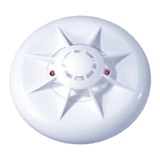
1.1 The FT – A1 (FT – A2, FT –B) heat detectors are designed to control ambient temperature indoors.
1.2 When exceeding the threshold ambient temperature value in guarded premises the detector forms
the alarm signal for CP.
1.3 The Fire mode is indicated with 2 red optical indicators.
1.4 The indication of Fire mode depends on the AL type the detector is connected to. The indication in
DC AL is made with continuous light of optical indicators, and in AC AL – with flashing.
1.5 The detector indicates standby mode with short-term flashes of the red LED.
1.6 The detector is intended to operate all day long with CP by 2-wire AL with rated loop voltage
12/24V.
1.7 The MUSH-2 or MUSH-3 modules should be applied to connect detectors to 4-wire CP. .
2.1 Static response temperature range, ° :
- FT – A1
- FT – A2
- FT –
2.2 Supply voltage range, V
2.3 Standby current consumption at 30 V max,
2.4 Fire current consumption
2.5 Internal resistance in Fire mode at 20 mA, Ohm
2.6 Dimensions, mm
2.7 Weight, g
2.8 Average lifespan, years
2
FT – A1, FT – A2, FT –B
HEAT DETECTORS
Model
2 TECHNICAL SPECIFICATIONS
set by external resistor in value range
USER'S
MANUAL
Type
Fixed temperature
Fixed temperature
Fixed temperature
1 PURPOSE
, m
EN 54-5:2003 class
1
2
54 – 65
54 – 70
69 – 85
9 - 30
0,1
5 - 20
500
85 × 33
50
10
Table 1
Advertisement
Table of Contents

Related Manuals for Aparton FT-A1

Summary of Contents for Aparton FT-A1
- Page 1 USER’S MANUAL FT – A1, FT – A2, FT –B HEAT DETECTORS The detectors comply with EN 54-5:2003. Compliance of the detectors with the type and class appear in Table 1. Table 1 Model Type EN 54-5:2003 class FT – A1 heat detector Fixed temperature FT –...
- Page 2 3 ITEMS SUPPLIED WITH THE DETECTOR Name Quantity Note Heat detector FT – A1 Up to 100 pcs (FT – A2) (FT – ) Manual 1 pc. Per a package Package 1 pc. Per 100 pcs MUSH-2 or MUSH-3 modules can be supplied for connection with a 4-wire CP if ordered separately. 4 PLACEMENT AND INSTALLATION 4.1 You should choose places to locate detectors where there are provided: - minimal construction vibrations;...
- Page 3 7.2 The manufacturer repairs or replaces detectors within the guarantee term provided the rules of installation, timely maintenance, transportation and storage of detectors have been kept. 7.3 In the case that faults according to the reclamation have been removed the guarantee term is prolonged for the while detectors were not in use because of faults.
- Page 4 Figure 3 WIRING DIAGRAM TO DC CONTROL PANEL Contacts «1», «2», «3», «4» are marked on the base and on PCB of the detector. Resistors value is specified by control panel manufacturer. Feasible values: 24V: EOL resistor= (2,4-3,9) kOhm, CLR=(0,68-3,6) kOhm 12 V: EOL resistor = (1,2-2) kOhm, CLR =(0,1-1,5) kOhm Figure 4 WIRING DIAGRAM TO AC CONTROL PANEL...
- Page 5 Figure 5 WIRING DIAGRAM FOR CONNECTION OF DETECTORS TO 4-WIRE AL THROUGH MUSH-2 MODULE EOLR (from 1 to 5 kOhm) and CLR (from 2 to 15 kOhm) are specified by control panel manufacturer. EOL resistor = 1,5 kOhm. Figure 6 WIRING DIAGRAM FOR CONNECTION OF DETECTORS TO 4-WIRE DC AL THROUGH MUSH-3 MODULE EOLR...
Need help?
Do you have a question about the FT-A1 and is the answer not in the manual?
Questions and answers