Advertisement
Quick Links
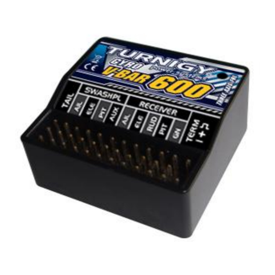
Flybarless System. Firmware V3.01
Preface
The Turnigy® V-Bar 600 is an extremely high quality precise controller and stabilizer for the swash plate and tail rotor of a
model helicopter flight control system. It has super-stabilization and super-response to control input. This makes for incredible
stability and agility. The programmability allows for performance settings from smooth scale to sport or hard 3D flying.
Flybarless also means longer flight times and a tremendous reduction in parts and aerodynamic drag. You no longer need to use
a separate external tail gyro, resulting in reduced weight, with a large cost savings. The Turnigy® V-Bar 600 offers 4 switchable
flight modes.
Technical details:
●MEMS Gyro Sensors in three axes
●Digital signal processor
●Operating voltage: 4-10 Volts, current < 80mA
●Temperature range: -10°C to +50°C
●Size: 33x34x18 mm
●Weight: 15 g
●Servo compatibility: 1520uS/333Hz, 1520uS/250Hz, 1520uS/167Hz, 960uS/333Hz (tail only) and 760uS/333Hz Digital
servos. Also, standard 1520uS/71Hz Analog servos.
●Supplied: Foam and double-side adhesive tape and Stainless steel plate.
Installation
:
Only use the thick double sided adhesive pads when installing the Turnigy® V-Bar 600 unit on an electric helicopter. If
installing on to a nitro or turbine helicopter, you may want to use the two double sided adhesive pads on the bottom plus a
stainless plate on the top of these, then a thin double sided adhesive pad on the top layer, for better vibration isolation.
Turnigy
V-Bar 600
®
Advertisement

Related Manuals for Turnigy V-Bar 600


Summary of Contents for Turnigy V-Bar 600
- Page 1 Preface The Turnigy® V-Bar 600 is an extremely high quality precise controller and stabilizer for the swash plate and tail rotor of a model helicopter flight control system. It has super-stabilization and super-response to control input. This makes for incredible stability and agility.
- Page 2 As shown in the pictures below, when installing the Turnigy® V-Bar 600 unit to your helicopter, you can choose the following four mounting positions. If the Turnigy® V-Bar 600 unit is installed on bottom of the helicopter, the same four directions can be chosen as well.
- Page 3 Turnigy® V-Bar 600 port connection layout Important: The gain channel (GN) input positive (centre) pin is isolated from all the other positive pins. The positive (centre) pins of both the rudder input and tail outputs terminals are also isolated, but connected together, from the remaining terminals on the unit.
-
Page 4: Basic Setup Instructions
1: TAIL BASE SETUP, 2: SWPL BASE SETUP Connect the three servos to the Turnigy® V-Bar 600 unit. Refer to the servo diagram further on in the manual. See - SWPL-TYPE - Swash plate Type Selection ... -
Page 5: Status Led
Restart the unit and let it power-up in normal flying mode - LED Solid ON. Set the gain channel (e.g. GEAR channel) on your transmitter so that the Turnigy® V-Bar 600 is in flight mode zero - 0 ... -
Page 6: Sensor Settings
Turnigy® V-Bar 600 Main menu configuration steps. These are in the correct order to be completed. Pre-flight Initial setup 1: TAIL BASE SETUP 2: SWPL BASE SETUP 3: TX CALIBARTION 4: SENSOR SETTINGS 5: TX DEADBAND 6: AUTOTRIM 7: GN-MODE Post setup –... - Page 7 – Initial Pre-flight setup menu 5: TX DEADBAND RUD-DEAD AIL-DEAD ELE-DEAD RETURN 6: AUTOTRIM – Initial setup for autotrim mode. This needs to be set for all flight modes used – Initial setup to enable and test the flight modes 7: GN-MODE 8: TAIL ROTR PARAM –...
- Page 8 1: TAIL BASE SETUP bmenu configuration steps in detail TAIL-SRV - Rudder servo type selection Menu Items Description Futaba:S9253, S9254, S9650, S9257, S3153 JR:8900G、DS3405、DS3500 152-33 Hitec:HS-5084MG、HS-5925MG 1520uS 333Hz LogicTech:3100G (Default) If the servos operate in an abnormal state, it is not adapting to the 333 Hz frequency. Select an option with lower frequency of 152-25 (1520us/250Hz) or 152-07 (1520us/71Hz).
- Page 9 Turnigy® V-Bar 600 using 3-point (120°) link method. HR-3 (Default) Transmitter should be in H-3 mode. Turnigy® V-Bar 600 controls 3 swash plate servos after being mixed controlled by Turnigy® V-Bar 600 using 3-point (135°/140°) link method.
- Page 10 GYRO-POS - Turnigy® V-Bar 600 Placement Selection Item Content Turnigy® V-Bar 600 runs parallel to the helicopter (nose) and can be placed at the top and the bottom. It must not be powered on when changing the placement. NORM (Default) Turnigy®...
- Page 11 3: TX CALIBRATION Submenu Configuration Steps Ensure all controls are working correctly. In the primary setting mode, apply positive collective pitch. Check whether the directions of swash plate servos (AILERON, ELEVATOR and PITCH) are correct. If incorrect, the AILERON, ELEVATOR and PITCH servo direction can be changed via your transmitter – servo reverse. This step needs to be completed before continuing on.
- Page 12 AIGY-DIR - Calibration Direction Selection for Aileron Sensor Item Content NORM Lift the helicopter, incline the body with left higher than right, the swash plate shall be calibrated with left lower than right, if it is calibrated with left higher than right, please adjust the data to 「REV」 (default) Lift the helicopter, incline the body with left higher than right, the swash plate shall be calibrated with left lower than right, if it is calibrated with left higher than right, please adjust the data to 「NORM」...
- Page 13 ELE-DEAD - Elevator Stick Dead Zone Menu items Description The swash plate will have no elevator response within elevator dead zone. This is the neutral point 5 ~ 100 of the elevator stick. When the value is higher, the dead zone is larger. The model will have no (Default 6) elevator response within this dead zone of the stick.
- Page 14 (microseconds). Y is the currently selected flight mode (0-3). Moving the gain switch changes the flight mode. The Turnigy® V-Bar 600 unit can have up to four different flight modes. The flight mode corresponds to the pulse width of the gain (GN) channel input.
- Page 15 RUDRSTOP - Rudder Right Piro Stop Gain Menu items Description 60 - 180 The sensitivity of hovering and clockwise spin. The stop speed used for preventing the side wind, (Default 100) hovering shift and clockwise rotation. The sensitivity is RUDRSTOP*TAILGAIN when the hovering and clockwise rotation stop. If the ability to prevent side wind is poor, hovering drifts rightward, or slow clockwise tail rotation Suggestion stopping speed, increase the RUDRSTOP value.
- Page 16 CYC-COMP - Compensation of cyclic pitch to tail rotor Item Description A change in cyclic pitch will cause a change in head speed of the main rotor, as well as causing a -100 - +100 tail deviation. Adjust the CYC-COMP value until the torque change can be offset completely. If (Default 0) the torque change causes tail deviation counter-clockwise, compensate rightward rudder direction input, i.e.
- Page 17 AILLSTOP - Aileron Leftward Stop Gain Item Content 60 - 160 The stopping gain when banking leftward. The stop speed against side-wind and banking leftward. (Default 100) AILRSTOP - Aileron Rightward Stop Gain Item Content 60 - 160 The stopping gain when banking rightward. The stop speed against side=wind and banking (Default 100) rightward.
- Page 18 Press any of the following keys „+10, -10, +1, -1‟, on the LCD programmer to download the parameters from the LCD programmer‟s memory to the Turnigy® V-Bar 600 unit in the current flight mode. Repeat this step for all flight modes.
- Page 19 Parameter Reference sheet Current Default setting Range setting 152-33 1: TAIL BASE SETUP TAIL-SRV -100 to +100 RUD-TRIM 130 to 240 RUD-LEND 130 to 240 RUD-HEND 152-07 2: SWPL BASE SETUP SWPL-SRV HR-3 HR-3 or H-3 SWPL-MIX NORM NORM or ROT-90 GYRO-POS 10 - 240 CYCLIC LIMIT...
Need help?
Do you have a question about the V-Bar 600 and is the answer not in the manual?
Questions and answers