Table of Contents
Advertisement
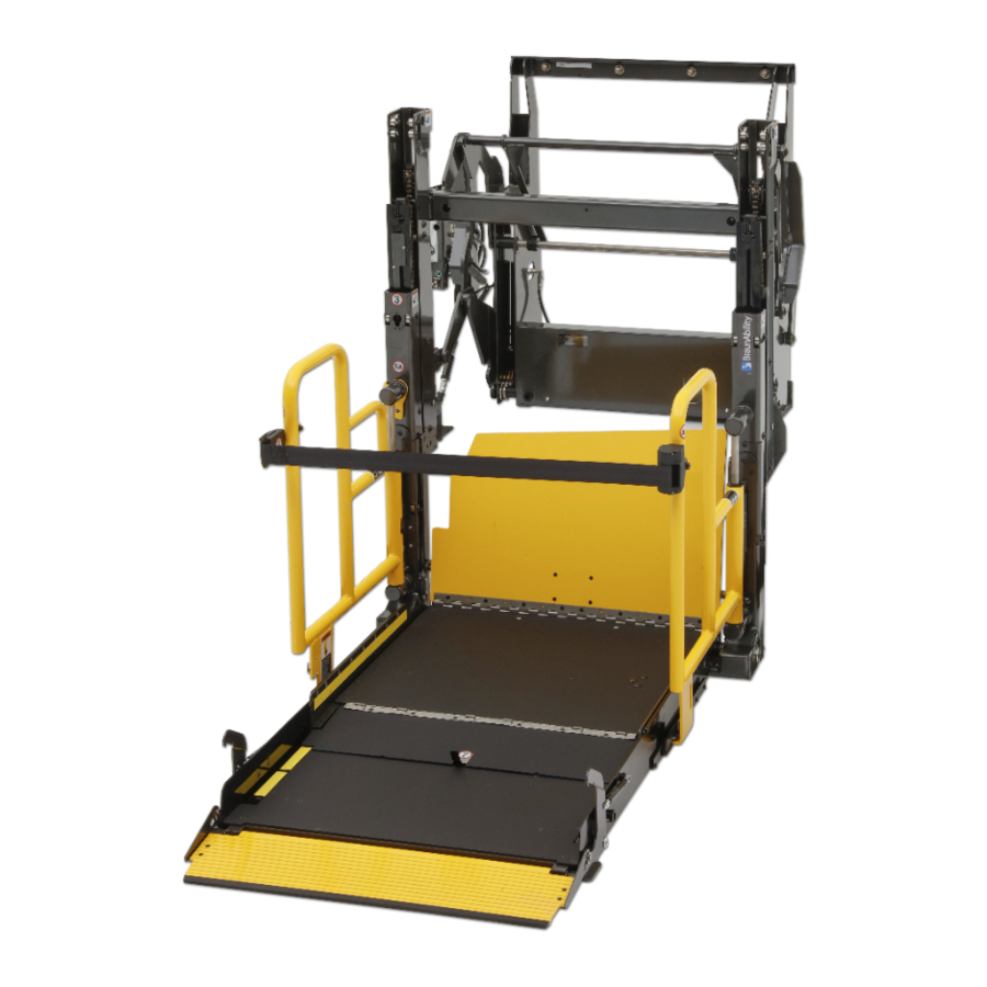
Operator's Manual for:
Public Use Wheelchair Lifts
"DOT — Public Use Lift" verifies that this platform lift meets the
"public use lift" requirements of FMVSS No. 403. This lift may be
installed on all vehicles appropriate for the size and weight of the
lift, but must be installed on buses, school buses, and multi-
purpose passenger vehicles other than motor homes with a gross
vehicle weight rating (GVWR) that exceeds 4,536 kg (10,000 lb).
"Providing Access to the World"
International Corporate Hdqrs: P.O. Box 310
1-800-THE LIFT
Patent #5,261,779
Patent #5,261,779
Patent #6,065,924
Patent #6,065,924
Patent #6,238,169
Patent #6,238,169
30651 Rev. B
Patent #6,464,447
October 2006
Patent #6,464,447
DOT — Public Use Lift
DOT — Public Use Lift
(574) 946-6153
FAX: (574) 946-4670
Patent #6,599,079
Patent #6,599,079
Patent #6,692,217
Patent #6,692,217
Patent #6,739,824
Patent #6,739,824
Patents Pending
Patents Pending
®
®
Winamac, IN 46996 USA
W ARNING
Read manual
before operating
lift. Failure to do
so may result in
serious bodily
injury and/or
property damage.
Keep manual in
lift storage pouch.
Advertisement
Table of Contents

Related Manuals for Braun NL Series


Summary of Contents for Braun NL Series
- Page 1 Operator's Manual for: Public Use Wheelchair Lifts DOT — Public Use Lift DOT — Public Use Lift “DOT — Public Use Lift” verifies that this platform lift meets the “public use lift” requirements of FMVSS No. 403. This lift may be installed on all vehicles appropriate for the size and weight of the lift, but must be installed on buses, school buses, and multi- purpose passenger vehicles other than motor homes with a gross...
- Page 2 Congratulations We at The Braun Corporation wish to express our fullest appreciation on your new purchase. With you in mind, our skilled craftsmen have designed and assembled the finest lift available. This manual includes safety precautions, lift operating instructions, man- ual operating instructions, and instructions for maintenance and lubrication procedures.
-
Page 3: Table Of Contents
Warranty/Registration Instructions ... 2, 3 Lift Terminology Lift Terminology Illustration ... 4 Introduction ... 5 Direction ... 5 Lift Components ... 6, 7 Vehicle and Lift Interlocks ... 7 Lift Actions and Functions ... 8 Lift Operation Safety Safety Symbols ... 9 Lift Operation Safety Precautions ... -
Page 4: Warranty And Registration Instructions
ADDRESS CITY TELEPHONE STATE TO VALIDATE WARRANTY REGISTRATION CARDS MUST BE RETURNED TO THE BRAUN CORPORATION. Page 2 the other card and mail it to The Braun Corporation. The warranty is provided on the back cover of this manual. The warranty cards must be processed to activate the war- ranty. - Page 5 Warranty and Registration Instructions Model No. Series No. Serial No. Pump Code Cylinder Code Date of Manufacture Note: This information must be provided warranty claim or ordering parts. Keep for future use. Page 3...
-
Page 6: Lift Terminology Illustration
Visual Lift-Tite Threshold Towers (2) Warning Audible Threshold Warning Hand-Held Pendant Control Pump Module Base Plate Bottom Parallel Arms (2) Rotating Pivot Slide Arms (2) Platform Pivot Arms (2) Pump Side Vertical Arm Outer Barrier Cylinder (not visible -underside of platform) Platform Side Plates (2) Page 4 ™... -
Page 7: Introduction
(pump module located on op- posite end of base plate). Refer to the Lift Terminology lift components. Lift operation procedures are identical for all NL Series lift models. The operating instructions contained in this manual and appearing on lift- posted operating instructions... -
Page 8: Lift Components
Lift Components Refer to the Lift Terminology Il- lustration on page 4. Pump Module: The lift-mounted pump module consists of the hy- draulic pump, the manual hand pump, the electronic control board and electrical components that power the lift electric/hy- draulic systems. -
Page 9: Vehicle And Lift Interlocks
Inner Roll Stop: NL Series lift models are equipped with an automatic inboard roll stop that also serves as the bridge plate. The roll stop bridges the gap between the lift platform and the automatically rotates from the horizontal position to the verti- cal position as the lift lowers and raises. -
Page 10: Lift Actions And Functions
Lift Actions and Functions DEPLOY (A-C) A. UNFOLD (Out) - Platform Unfold: Unfold is the action of the platform rotating out and down from the fully-stowed (horizontal) position when the UNFOLD switch is pressed. B. DOWN - Platform Lower: Down is the action of the platform to fully-lowered (ground level) position when the DOWN switch is pressed. -
Page 11: Lift Operation Safety
Safety Symbols SAFETY FIRST! Know That... All information contained in this manual and supplements (if included), is pro- vided for your safety. Familiarity with proper operation instructions as well as proper maintenance procedures are necessary to en- sure safe, troublefree operation. Safety precautions are provided to identify potentially hazardous situations and provide instruction... -
Page 12: Operation Notes And Details
W ARNING If the lift operating instructions, manual operating instructions and/or lift operation safety precautions are not fully understood, contact The Braun Corporation immedi- ately. Failure to do so may result in serious bodily injury and/or property damage. W ARNING Inspect lift before operation. - Page 13 W ARNING Whenever a wheelchair passenger (or standee) is on the platform, the: • Passenger must be positioned fully inside yellow boundaries • Wheelchair brakes must be locked • Inner roll stop and outer barrier must be up (vertical) • Outer barrier latch must be fully engaged •...
- Page 14 W ARNING If the lift operating instructions, manual operating instructions and/or lift operation safety precautions are not fully understood, contact The Braun Corporation immedi- ately. Failure to do so may result in serious bodily injury and/or property damage. W ARNING Outer barrier must be fully unfolded (ramp position) until front and rear wheelchair wheels cross the barrier when loading or unloading at ground level.
- Page 15 Keep owner’s (operator's) manual in lift-mounted manual storage pouch at all times. W ARNING Never modify (alter) a Braun Corporation lift. Do not use accessory devices not authorized by The Braun Corporation. W ARNING W ARNING Do not remove any guards or covers.
-
Page 16: Operation Notes And Details
Failure to do so may result in serious bodily injury and/or property damage. Page 14 NL Series “Public Use” lift models operated by an attendant. The Lift Operating Instructions contained in this manual and posted on the lift provide instructions for op- eration of the lift only. -
Page 17: General Safety
Operation Notes and Details General Safety: The lift operator (attendant) and bystanders must keep clear of the area in which the lift operates and clear of all moving parts. Lift attendants Control Switches must ensure that lift occupants (passengers) keep hands, arms and all other body parts within the lift occupant area and clear of moving parts. -
Page 18: Lift-Tite Latches
Failure to do so may result in serious bodily injury and/or property damage. Page 16 components if not clearly depict- ed in this section. Contact The Braun Corporation at 1-800-THE ® LIFT immediately if any of this Latch En- gagement Pin (Roller) -
Page 19: Lift-Tite Latches
Operation Notes and Details vent the platform from unfolding from the stowed position in the event of platform drift. Due to the “all-hydraulic” operation of the dual-cylinder NL, hydraulic seepage may occur. Any of these conditions may result in platform drift (failure to hold the platform in the folded or raised position). -
Page 20: Inner Roll Stop
Operation Notes and Details Lift Features (continued) Inner Roll Stop: NL Series lift models are equipped with an automatic inner roll stop that also serves as the bridge plate (inner roll stop photos below). When the UNFOLD switch is Page 18... -
Page 21: Inner Roll Stop
Operation Notes and Details W ARNING Discontinue lift use immediately if any lift component does not operate prop- erly. Failure to do so may result in serious bodily injury and/or property damage. horizontal (bridging) position el. The roll stop must overlap the lift base plate a minimum 1/2". -
Page 22: Outer Barrier
Operation Notes and Details Lift Features (continued) Discontinue lift operation im- mediately if the outer barrier does not operate properly. Outer Barrier Latch: A spring- loaded latch engages the outer Fully-Engaged Outboard Barrier Latch 3" Latch Foot Page 20 barrier when the barrier rotates upward from ramp position to the vertical position (UP switch is pressed to raise the platform... -
Page 23: Outer Barrier Latch
Operation Notes and Details The latch disengages the barrier when the platform lowers fully (reaches ground level) and the latch foot contacts the ground (latch raises above the barrier). Outer Barrier and Latch Op- eration: The lift attendant must press the DOWN switch to lower the platform fully to the ground. -
Page 24: Lift Passengers
The Braun Corporation. Braun NL Series lifts permit both inboard and outboard facing of wheelchair and mobility aid us- ers and accommodate persons using walkers, crutches, canes... -
Page 25: Yellow Boundaries
Operation Notes and Details cated on the pump-side platform side plate. A yellow boundary posite platform side plate. Yellow plastic caps are placed on the dual handrails. The threshold warning plate is powder-coated yellow to iden- tify the platform threshold area. Interlock: A visible and audible threshold warning system will ac- tivate if the threshold area is oc-... - Page 26 Page 24 outlined in this manual, discon- tinue lift use immediately and contact The Braun Corporation sales representative in your area or call The Braun Corpora- ® tion at 1-800-THE LIFT . One of our national Product Support representatives will direct you to an authorized service techni- cian who will inspect your lift.
-
Page 27: Wheelchair-Equipped Occupant Seat Belts
Operation Notes and Details Wheelchair-Equipped Occupant Seat Belts The Braun Corporation recom- mends wheelchair passengers position and buckle their wheel- W ARNING Position and secure (buckle, engage, fasten, etc.) the wheelchair-equipped occupant seat belt before loading onto the wheelchair lift platform. -
Page 28: Preventive Maintenance
Operation Notes and Details Transit agency supervisors should train and educate their lift attendants on the proper use and operation of the wheelchair lift if it is not possible for the attendants to review the safety precautions and operation pro- cedures with the wheelchair lift sales representative. -
Page 29: Lift Operating Instructions
Lift Operating Instructions photos depict lift model NL917IB. Instruc- tions and procedures are appli- cable for all NL Series lift models. Lift-posted Warnings and Lift Operating Instructions decal 30695 provides lift operating instructions. Replace any missing, worn or illeg- ible decals. - Page 30 Lift Operating Instructions Page 28 Open Door(s) and Secure To Unfold Platform: Stand clear and press the UN- FOLD switch until the platform stops (reaches - unfolds fully). Release switch. Note: In event platform does not unfold, press FOLD switch to ™...
- Page 31 Lift Operating Instructions 32525 FOLD 2. Press DOWN switch until the en- DOWN UNFOLD 32526 3. Unlock wheelchair brakes and To Unload Passenger (continued): tire platform reaches ground level (see Photo B) and the outer bar- rier unfolds fully (ramp position). See Photo C.
- Page 32 Lift Operating Instructions To Load Passenger: 1. Read Notes below! Load pas- senger onto platform and lock wheelchair brakes. See Photo G. Note: Outer barrier must be fully unfolded (ramp position) until the entire wheelchair (or standee) has crossed the outer barrier. See Photos E and F.
-
Page 33: Lift Operating Instructions
Lift Operating Instructions 32525 FOLD 2. Press UP switch (Photo I) to fold DOWN UNFOLD 32526 3. Unlock wheelchair brakes and 32525 FOLD DOWN UNFOLD 32526 To Load Passenger (continued): outer barrier UP fully (vertical - see Photo H), and raise the plat- form to . -
Page 34: Nhtsa Operations Checklist
NHTSA Operations Checklist installation. This operational checklist can be used at any time to verify the lift is fully functional. Vehicle movement is prevented unless the lift door is closed, ensuring the lift is stowed. Lift operation shall be prevented unless the vehicle is stopped and vehicle movement is prevented. -
Page 35: Manual Operating Instructions
Manual Operating Instructions If you experience power or equipment failure, refer to the Manual Operating Instructions to operate the lift. Instructions and photos are provided for Turn wing 1/4 turn. Pump Cover Lock Unlock all steps that differ from stan- dard lift operation procedures. - Page 36 Manual Operating Instructions ing Instructions for all normal lift operation procedures (such as loading and unloading passen- gers). Follow all Lift Operation Safety Precautions! Hand Pump Note: Close backup pump release valve securely before operating electric pump. Page 34 Remove the pump cover to gain access to the pump handle and the hand pump.
- Page 37 Manual Operating Instructions Remove pump cover to access hand pump and pump handle as outlined on page 33. Refer to release valve photos and illustra- tion on page 34. Open Close (Down) (Up/Stop) To Unfold Platform (Out): Using hand pump handle (Photo B): 1.
- Page 38 Manual Operating Instructions Remove pump cover to access hand pump and pump handle as outlined on page 33. Refer to release valve photos and illustra- tion on page 34. Open Close (Down) (Up/Stop) Page 36 Up (To Raise): Using hand pump handle: 1.
- Page 39 Manual Operating Instructions To Store Pump Handle: 1. Insert bottom of handle behind bottom clip. See page 33. 2. Rotate top clip to secure (lock) handle. To Install Pump Cover: 1. Position cover over module back cover and red warning light.
-
Page 40: Decals And Antiskid
25675 W ARNING LIFT POWER Lift installation and servicing prohibited by anyone who has not been certified by The Braun Corporation Sales and Service School. Certified service technicians should call 1-800-THE LIFT to receive applicable installation/service manual. Failure to follow this policy may result in serious bodily injury and/or property damage. - Page 41 32410 LCD Lift Codes Listed below are codes that the lift controller outputs during lift operation. The codes will be displayed on an LCD screen located on the lift control board inside the pump module. Non-Flashing Numbers 01 – Platform stowed 57 –...
-
Page 42: Decals And Antiskid
22249 25652 W ARNING Contact The Braun Corporation before adjusting hydraulic pressure relief valve. Failure to do so may result in serious bodily injury and/or property damage. 22249 25652 W ARNING Size 2" x 12" Replace missing or 2" x 12"... -
Page 43: Maintenance And Lubrication
Braun authorized service represen- tative at the scheduled intervals according to the number of cycles. NL Series lifts are equipped with hardened pins and self-lubricating bushings to decrease wear, provide smooth operation and extend the ser- vice life of the lift. - Page 44 Contact your sales represen- tative or call The Braun Corporation at 1-800-THE LIFT ® . One of our national Product Support repre- sentatives will direct you to an authorized service technician who will inspect your lift.
-
Page 45: Lubrication Diagram
Parallel Arm Pivot Pins (8) Rotating Pivot Slide Arm UHMW Slide (4) Rotating Pivot Slide Arm Pivot Pins Platform Fold Axles (2) Platform Pivot Pin (2 Points) Lift-Tite Latch Roller Assemblies (2) Outer Barrier Latch LO Outer Barrier Latch Lever Lift-Tite Latches (Tower Pivot Points - 2) LO Lift-Tite Latch Dampening Spring... -
Page 46: Maintenance And Lubrication Schedule
Maintenance and Lubrication Schedule Outer barrier hinge pivot points (2) Outer barrier latch (pivot/slide points) Outer barrier latch lever pivot points ™ Lift-Tite latches (tower pivot points - 2) Lift-Tite ™ latch gas (dampening) spring pivot points (2 springs - 4 points) Inspect Lift-Tite ™... - Page 47 Maintenance and Lubrication Schedule Perform all procedures listed in previous section also Platform pivot pin bearings (2) Platform fold axles (2) Inner roll stop lever bearings (2) Inner roll stop lever slot (2) Rotating pivot slide arm pivot pins (2) 1500 Parallel arm pivot bearings (16) Cycles...
- Page 48 Maintenance and Lubrication Schedule continued Perform all procedures listed in previous section also Inspect handrail components for wear or damage, and for proper operation Inspect microswitches for securement and proper adjustment. Make sure lift operates smoothly Inspect external snap rings: 1500 •...
- Page 49 (if equipped) Resecure, replace or correct as needed. Resecure, replace or correct as needed Use Braun 32840-QT (Exxon ® Univis HVI 26) do not mix with Dextron III or other lowered fully and roll stop unfolded fully. Fill (neck).
- Page 50 Maintenance and Lubrication Schedule continued Perform all procedures listed in previous section also Inspect parallel arms, bushings and pivot pins for visible wear or damage Inspect parallel arm pivot pin mounting bolts (8) Inspect platform pivot pin, bushings and vertical arms for wear, damage and positive securement Inspect upper/lower fold arms, rotating pivot slide 4500...
- Page 51 Maintenance and Lubrication Schedule Mounting 4500 Cycles Decals and Antiskid Repeat all previously listed inspection, lubrica- Consecutive tion and maintenance procedures at 750 cycle 750 Cycle intervals. Intervals Check to see that the lift is securely anchored to the vehicle and there are no loose bolts, broken welds, or stress fractures.
- Page 52 "Providing Access to the World" ® Over 300 Braun Dealers Worldwide...
- Page 53 All illustrations, descriptions and specifications in this manual are based on the latest product information available at the time of publication. The Braun Corporation reserves the right to make changes at any time without notice. at the time of publication. The Braun Corporation reserves the right to make changes at any time without notice.
Need help?
Do you have a question about the NL Series and is the answer not in the manual?
Questions and answers