
Summary of Contents for Hawido 1401
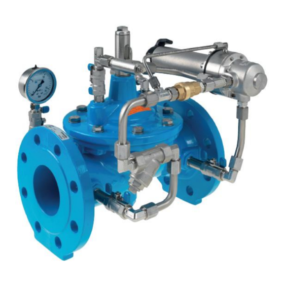
- Page 1 HAWIDO - REGULATING VALVES Instruction for Pressure relief and pressure retention valve with backflow prevention Type 1401 ND40 – ND200 Keep this instruction manual at the location of the valve!
- Page 2 Example of rating plate After the commissioning, enter the following data and make use of this additional information regarding the valve type, pressure and flow ratios when consulting the manufacturer or the supplier or asking them questions: ……………… ………………….. Serial number: ...........
-
Page 3: Table Of Contents
CONTENTS DESCRIPTION 1. F UNCTION 2. G ENERAL SAFETY INSTRUCTIONS 3. R ECOMMENDED INSTALLATION B. COMMISSIONING 1. F (1401) UNCTIONAL DIAGRAM 2. P REPARATORY WORK 3. V ENTING 4. A DJUSTMENTS 5. S ETTING THE REACTION SPEED 6. C HECK FUNCTION 7. -
Page 4: Description
Damage to property and injuries to persons could occur as a result of improper installation, commissioning, operation and maintenance. The Hawle regulating valve (HAWIDO) has been designed for use in drinking and process water supplies. Other application media only after consultation with the manufacturer. -
Page 5: Recommended Installation
If the HAWIDO 1400 is used as a safety valve the shutoff gate valve on the outlet side can be omitted. Before the installation, check that no coarse foreign objects can penetrate into the HAWIDO. -
Page 6: Commissioning
B. Commissioning Functional diagram (1401) Components 1 Main valve 1200 2 Ball valve (A, B, C) 3 Filter 4 Orifice plate 5 One-way flow restrictor (A, B) 6 Control valve 7 Pressure gauge 8 Position indicator Electrical position indicator (optional) Valve opening... -
Page 7: Venting
Venting Procedure: Slowly open the inlet gate valve on the inlet side until water flows into the valve. The valve fills with water and the air escapes through the open vent holes. When all the air has been expelled by venting the valve in the control line, re-tighten the threaded pin. Check that all the screw connections are properly sealed, and re-tighten if necessary. -
Page 8: Setting The Reaction Speed
Setting the reaction speed If the HAWIDO does not operate quietly, or if pressure shocks occur in the supply network, this can be corrected by the corresponding adjustment of the one-way flow restrictor (4). Procedure: Loosen the locknut. Screw in the set screw clockwise with a screwdriver until the valve operates quietly. -
Page 9: Fault Finding
C. Fault finding Symptoms Possible cause Action Valve does not open One-way flow restrictor blocked Replace or unscrew the set screw several times until the valve functions properly One-way flow restrictor closed Unscrew the set screw until the too far valve functions properly Valve does not open Control valve screw over-... -
Page 10: Putting Out Of Service And Maintenance
D. Putting out of service and maintenance Putting out of service The operating valve must first be shut off hydraulically by proceeding as follows: • Slowly close the gate valves before and after the valve • Slowly close the ball valves (2A, 2B, 2C). The valve has now been taken out of operation, and a service can be carried out. -
Page 11: To 5-Year Maintenance
Checking the valve • Remove the optical position indicator or plug on the valve cover. • Check that the valve spindle moves easily by raising and lowering it with the threaded rod. • Assemble optical position indicator or plug. Putting back into service •... -
Page 12: Repair Kits And Spare Parts
-10- Functional check of the one-way flow restrictor • Undo the locknut • Screw in the throttle screw, and then unscrew it as far as it goes • Screw in again a few turns. This process must be easy and meet little resistance Checking the valve •... -
Page 13: Base Valve Dn 40 To Dn 200 (Drawing)
-11- 3.1 Base valve DN 40 to DN 200 (drawing) 08.12.2011/plü... -
Page 14: Main Valve (Parts List)
-12- 3.2 Main valve (Parts list) Item. Description Material Article number DN 40 DN 50 DN 65 DN 80 DN 100 Body GGG 40 1004 040 000 1004 050 000 1004 065 000 1004 080 000 1004 100 000 Valve cover GGG 40 1014 050 000 1014 050 000... - Page 15 -13- Article number Item Description Material DN 125 DN 150 DN 200° DN 200^ Body GGG 40 1004 125 000 1004 151 000 1004 200 000 1004 200 016 Valve cover GGG 40 1014 125 000 1014 151 000 1014 200 000 1014 200 000 Spindle guide cover INOX...
-
Page 16: Dav Stainless Steel Control Valve Dn 3/8" Pn 10/16/25 (Drawing)
-14- 3.3 DAV stainless steel control valve DN 3/8" PN 10/16/25 (drawing) 01.09.2017/plü... -
Page 17: Dav Stainless Steel Control Valve Dn 3/8" Pn 10/16/25 (Parts List)
-15- 3.4 DAV stainless steel control valve DN 3/8" PN 10/16/25 (parts list) Item Description Material Article number Control casing Stainless steel 1100 200 000 Cover Stainless steel 1108 200 000 O-ring NBR70 0180 020 025 Diaphragm DN3/8 EPDM (W270) 1121 000 000 Seat Compact Form 1.0, blank Stainless steel... -
Page 18: Control Line Individual Parts And Accessories
-16- 3.5 Control line individual parts and accessories Master number Picture Size Art. number Designation further sizes possibly available stainless steel/NBR 3/8“ 0130 0130 012 000 stainless steel/NBR 1/2" 0130 016 000 Compound seal stainless steel/NBR 3/4" 0130 025 000 Stahl/NBR 1“... - Page 19 -17- 0401 3/8" stainless steel 0401 012 000 1/2" stainless steel 0401 016 000 Sleeve 3/4" stainless steel 0401 025 000 1" stainless steel 0401 032 000 DN 6 - 1/8" stainless steel 0411 006 004 0411 DN12 - 3/8" stainless steel 0411 012 012 Adjuster nipple DN 6 - 1/8"...
- Page 20 -18- 0545 Stainless steel Y-filter IG 3/8" 0545 112 002 Individual parts: Stainless steel dirt filter Stainless steel dirt filter 0545 900 051 Plug, complete for Y-filter, stainless 0545 112 010 steel 0545 112 011 Large seal for Y-filter, POM 0545 112 012 Small O-ring for plug 0545 116 000...
- Page 21 -19- 0620, 0621 AC coils with 0620 xxx xxx voltage indication Coils DC coils with 0621 xxx xxx voltage indication 0630 Appliance socket 0630 000 000 for electromagnet Appliance socket Connector modules for solenoid valves 0653 024 008 0653 Type LBV 24 DC 8S, incl. 2m cable Connector modules Connector modules for solenoid valves 0653 230 000...
- Page 22 -20- 1188 From serial number14252 (January 2003) 1188 065 100 Rep. Set DN40 to 100 1188 125 300 Control line DN125 to 300 From approx. serial number 25915 (June 2014, 1188 000 000 Filter type B (0545 112 002) 1188 000 001 DN40 to 100 DN125 to 200 Polyamide tube OD 6 mm, ID 4 mm...
-
Page 23: Optical Position Indicator (Drawing)
-21- 3.6 Optical position indicator (Drawing) DN 40 – DN 100 DN 125 – DN 300 12.03.2014/plü... -
Page 24: Optical Position Indicator (Parts List)
-22- 3.7 Optical position indicator (Parts list) Item Description Material Article number DN 40 DN 50 DN 65 DN 80 DN 100 Indicator pin Stainless 1992 000 050 1992 000 050 1992 000 080 1992 000 080 1992 000 100 steel Compound seal ½’’... -
Page 25: Annex
-23- E. Annex Torques When assembling the base valve and the control valves all bolts are checked with a torque spanner according to the following list. Lightly grease the bolts before assembling! Nominal size Hex bolt Strength Tightening torque class Target Max. -
Page 26: Hawle In Europe
-24- F. Hawle in Europe Addresses: Hawle Armaturen AG Hawlestrasse 1 telephone +41 (0)71 969 44 22 CH-8370 Sirnach fax +41 (0)71 969 44 11 www.hawle.ch Hawle Armaturen GmbH Liegnitzer Strasse 6 telephone +49 (0)8654 63 03 - 0 D-83395 Freilassing fax +49 (0)8654 63 03 60 www.hawle.de E. - Page 27 -25-...
Need help?
Do you have a question about the 1401 and is the answer not in the manual?
Questions and answers