Table of Contents
Advertisement
Quick Links
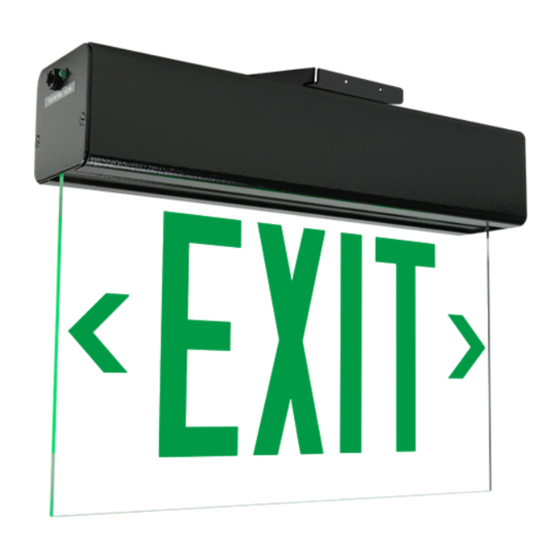
900E Series
READ AND FOLLOW ALL SAFETY INSTRUCTIONS.
When using electrical equipment, basic safety precautions should always be followed including the following:
• DISCONNECT AC POWER SUPPLY BEFORE SERVICING.
• Installation and servicing of this equipment should be performed by qualified service personnel only.
• Ensure that the electrical wiring conforms to the National Electrical Code NEC® and local regulations if
applicable.
• For use with metal enclosed wiring systems.
• Do not mount near gas or electrical heaters.
• Do not use outdoors.
• Equipment should be mounted in locations and at heights where it will not be readily subjected to tampering
by unauthorized personnel.
• The use of accessory equipment not recommended by the manufacturer may cause an unsafe condition.
• Any modification or use of non-original components will void the warranty and product liability.
• Do not use this equipment for other than intended use.
10070152 REV 1 - 10/19
IMPORTANT SAFEGUARDS
SAVE THESE INSTRUCTIONS!
Technical Support
■ (623) 580-8943 ■ technicalsupport@barronltg.com
1
800-533-3948 www.barronltg.com
Advertisement
Table of Contents

Related Manuals for BARRON Exitronix 900E Series

Summary of Contents for BARRON Exitronix 900E Series
- Page 1 900E Series Installation Instructions IMPORTANT SAFEGUARDS READ AND FOLLOW ALL SAFETY INSTRUCTIONS. When using electrical equipment, basic safety precautions should always be followed including the following: • DISCONNECT AC POWER SUPPLY BEFORE SERVICING. • Installation and servicing of this equipment should be performed by qualified service personnel only. •...
- Page 2 900E Series Installation Instructions Surface Ceiling, Surface Wall, or Flag Mount Fig. 1 J-box 1. Remove the end cap with the test button (if included) Mounting and LED indicator holes by loosening the (2) flat head Grommet Plate screws and set aside (Fig. 1). 2.
- Page 3 900E Series Installation Instructions Pendant Mount 1. Secure the mounting bracket to the mounting surface using appropriate hardware (not provided). Mounting 2. Thread a lock nut on one end of the extension rod. Bracket Firmly tighten the lock nut and ensure that it does not loosen by hand.
- Page 4 900E Series Installation Instructions Fig. 1 Recessed Ceiling or Recessed Wall Mount Note: If the “Rough-in Kit” for the 900E Series has been J-box Grommet Hanger pre-installed, proceed to step 7 below. Bars Recessed Housing 1. Cut a 3" x 15" opening in the ceiling or wall. Ensure that the opening is less than the trimplate dimensions of 3 7/8”...
- Page 5 900E Series Installation Instructions Fig. 4 9. Secure the homeplate assembly within the recessed housing using the (2) 6-32 screws and O-rings from before, along with (2) additional 6-32 screws and O-rings (provided). 10. Install the test button (if included) and LED indicator in the trimplate (Fig.
- Page 6 900E Series Installation Instructions Self-Test/Self-Diagnostics (G2) Operation The purpose of this option is to provide Self-testing and Self-diagnostic capabilities to the EXIT sign. At predetermined intervals, the EXIT sign will automatically switch into battery mode. Refer to the Self-Test Features section of this page for timing details.
Need help?
Do you have a question about the Exitronix 900E Series and is the answer not in the manual?
Questions and answers