Advertisement
101 N. Alloy Dr.
Fenton, MI 48430
Research, Development and Manufacturing of Precision Measuring Systems
LMI 200-S or LMI 200-SB to the LMI 440 or ASI DataMyte 501
1
This process will outline:
Section
I.
Configuration of the LMI 440 or ASI DataMyte 501
II.
Mastering the LMI 200-S or 200-SB
III.
How to verify the mastering of the LMI 200-S or 200-SB
September 21,
Form: CA 033
2004
Configuration and Mastering Instruction for the
R:\Quality\Calibration Instructions\CA 033.doc
2
Required Equipment:
1
LMI 440 or ASI DataMyte 501
2
LMI 200-S or 200-SB transducer
3
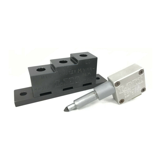
LMI 210 master block
4
LMI 6009 4 pin – 4 pin cable
Pages
Ph
(810) 714-5811
Fax (810) 714-5711
CustomerService@lmicorporation.com
4
3
2-4
5-6
7
Rev. A
Page 1 of 7
Advertisement
Table of Contents

Related Manuals for LMI 200-S

Summary of Contents for LMI 200-S
- Page 1 CustomerService@lmicorporation.com Research, Development and Manufacturing of Precision Measuring Systems Configuration and Mastering Instruction for the LMI 200-S or LMI 200-SB to the LMI 440 or ASI DataMyte 501 Required Equipment: LMI 440 or ASI DataMyte 501 LMI 200-S or 200-SB transducer LMI 210 master block LMI 6009 4 pin –...
- Page 2 Press 6 to highlight “Gage”. Press <enter>. It is recommended to assign simple user name to the gage files such as; 200, probe, lmi probe, etc. This will help to identify different setups. To assign a gage file name press the ▲ or ▼ to highlight gage “G4”* in the “Gage List”, and press <enter>...
- Page 3 E-mail support Phone support LMI Corporation techsupport@lmicorporation.com (810) 714-5811 Use the ▲, ►, ◄, or ▼ to highlight the desired character then press <enter>, repeat process until the gage file name is spelled out then press ►► to accept the new name.
- Page 4 E-mail support Phone support LMI Corporation techsupport@lmicorporation.com (810) 714-5811 Press the <menu> key to return to the “Main Menu”. If any changes were made in the “Gage Configuration” screen a save gage notification will appear. If the changes are intentional highlight “Save to current gage”...
- Page 5 (810) 714-5811 MASTERING INSTRUCTIONS LMI suggests that this process be performed at the start of every shift. Connect the transducer to Gage Port 4 of the data collector. If G5 was selected in gage configuration use Gage Port 5.
- Page 6 Gage Port highlighted Place the transducer into the top or “Lo” step of LMI 210 Master Block. Verify “Master Lo” is highlighted on the collector, press <enter>. Place the transducer into the bottom or “Hi” step of the LMI 210 Master Block. Verify “Master Hi”...
- Page 7 Add the raw value of step 2 and 3 together, this example shows 4.49 + 5.51 = 10.00.The sum of steps 2 and 3 needs to equal 10.00mm +/- .03. If at any time the 0.00mm or 10.00mm span is not within +/- .03mm the 200-S or 200-SB needs to be remastered.
Need help?
Do you have a question about the 200-S and is the answer not in the manual?
Questions and answers