Advertisement
Available languages
Available languages
Table of Contents
The illustrations in this document are generic; your control appearance may be slightly different from the ones shown.
Electrical wiring must be done by qualified personnel in accordance with all applicable codes and standards.
Before connecting wires, unplug the unit or switch power off at service panel and lock service disconnecting
means to prevent power from being switched on accidentally. Always wear safety glasses and gloves while
performing these instructions.
If ducts have to go through an unconditioned space (e.g.: attic), always use insulated ducts to prevent condensation
formation inside and outside ducts, which could cause material damage and/or mold growth. Moreover, if fresh air
to building duct and/or stale air from building duct goes/go through an unconditioned space, the unit must be set
to operate continuously in cold conditions (below 10°C/50°F). Continuous air movement inside ducts will prevent
condensation formation. The unit can be stopped temporarily for maintenance and/or repair purposes in such
conditions. (Refer to section 2.2 from unit User and Installer Manual for more details.)
INSTALLATION
Unplug the ventilation unit.
NOTE: If the control is to be installed in an electric box, go to step
7
Cut a 2
/
" x 1¾" hole in a wall, at a
8
convenient location for the control.
Route a cable (type 22/4) for the
control from the unit to this hole. See
figure at right.
Temporarily place the control over the
hole and mark both mounting screw hole
positions.
Remove the control, drill both screw
holes (3/16" Ø) in wall and insert the wall
anchors (included).
Strip the end of the cable to access the 4 wires (about 3"). Strip the
end of each wire (about 1/4"). Connect the wires to the terminals,
regardless of the wire color. Note which wire color has been
chosen for each terminal. See illustration below.
VC0236
Mount the control to the wall.
I
U
NSTALLATION AND
EE
VÄN
PART NO
READ AND SAVE THESE INSTRUCTIONS
Ø 3/16", typ.
VC0215A
12V
D-
D+
Gnd
VC0216
G
D
SER
UIDE FOR
EHUMIDISTAT
. 41302 V
ENMAR PART NO
!
WARNING
CAUTION
Perform
connector of the unit, as shown below. For more details, refer to
the installation manual of the ventilation unit.
NOTE: To avoid miswiring, refer to the notes taken at step
to match the wire color with the right terminal.
.
VC0235
Plug the ventilation unit and test the wall control.
VC0191
•
Press the CONT button to get continuous exchange ventilation
in MIN speed. The CONT indicator will light up. To quit this
mode, press the CONT button.
•
Press the INT button to get intermittent ventilation. The INT
indicator will light up. Within a one hour period, the system will
operate in MIN speed for 20 minutes. To quit this mode, press
the INT button.
•
If the maintenance indicator is lit, it means that the filter needs
to be cleaned or replaced. Once the filter is cleaned or replaced,
press the INT button for five seconds to reset the maintenance
indicator. If the maintenance indicator flashes, the LCD screen
on the unit will give the error code. Refer to the Troubleshooting
section in the ventilation unit user guide for more information.
•
At unit first boot, INT and CONT indicators blink alternately for
about 1 minute. If indicators continue blinking after this period, it
means that the communication cannot be established with the
ventilation unit. Make sure wires are correctly connected to the
wall control and unit terminals (refer to step 7).
C
ONTROL
. 41402
the
electrical
connection
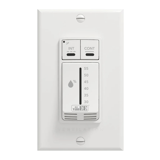
HOW TO USE THE CONTROL
The main button works following this
sequence:
• Click 1 = 30% RH
• Click 2 = 35% RH
• Click 3 = 40% RH
• Click 4 = 45% RH
• Click 5 = 50% RH
• Click 6 = 55% RH
• Click 7 = Dehumidistat disabled
• and so on
The indicator lights up as per the selected
RH. If the set point is exceeded, the system
will operate in MAX speed until the set point
is reached.
to
the
terminal
12V
D-
D+
Gnd
23847 rev. 02
Advertisement
Table of Contents

Related Manuals for vanEE DEHUMIDISTAT CONTROL 41302


Summary of Contents for vanEE DEHUMIDISTAT CONTROL 41302
- Page 1 NSTALLATION AND UIDE FOR EHUMIDISTAT ONTROL . 41302 V . 41402 VÄN PART NO ENMAR PART NO READ AND SAVE THESE INSTRUCTIONS The illustrations in this document are generic; your control appearance may be slightly different from the ones shown. WARNING Electrical wiring must be done by qualified personnel in accordance with all applicable codes and standards.
- Page 2 ’ ’ UIDE D INSTALLATION ET D UTILISATION DE LA COMMANDE DÉSHUMIDISTAT 41302 V 41402 VÄN PIÈCE N ENMAR PIÈCE N VEUILLEZ LIRE ET CONSERVER CES DIRECTIVES Les illustrations de ce document sont générales; l’apparence de votre commande peut légèrement différer de celles-ci. AVERTISSEMENT Le branchement électrique doit être effectué...
Need help?
Do you have a question about the DEHUMIDISTAT CONTROL 41302 and is the answer not in the manual?
Questions and answers