Table of Contents
Advertisement
Quick Links
TMG Corporate Website
Disclaimer:
All trademarks appearing within this PDF are trademarks of their respective owners.
Form 080/01
Complimentary Reference Material
This PDF has been made available as a complimentary service for you to assist in
evaluating this model for your testing requirements.
TMG offers a wide range of test equipment solutions, from renting short to long
term, buying refurbished and purchasing new. Financing options, such as
Financial Rental, and Leasing are also available on application.
TMG will assist if you are unsure whether this model will suit your requirements.
Call TMG if you need to organise repair and/or calibrate your unit.
If you click on the "Click-to-Call" logo below, you can all us for FREE!
TMG Products Website
Advertisement
Table of Contents

Subscribe to Our Youtube Channel
Related Manuals for Wiltron Site Master S110

Summary of Contents for Wiltron Site Master S110
- Page 1 Complimentary Reference Material This PDF has been made available as a complimentary service for you to assist in evaluating this model for your testing requirements. TMG offers a wide range of test equipment solutions, from renting short to long term, buying refurbished and purchasing new. Financing options, such as Financial Rental, and Leasing are also available on application.
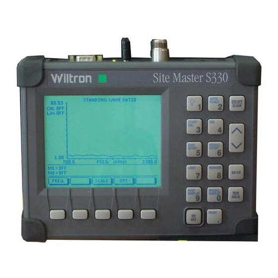
- Page 3 Site Master ™ S110, S111, S330, S331 Personal SWR/RL and Fault Location Tester User’s Guide Hand-Held Tester For Antennas, Transmission Lines And Other RF Components...
- Page 4 TRADEMARK ACKNOWLEDGEMENTS MS-DOS, Windows, and Windows for Workgroups are registered trademarks of the Microsoft Corporation. Site Master, Site Master 110, Site Master S110, Site Master S111, Site Master 330, Site Master S330, and Site Master S331 are trademarks of Wiltron Company.
-
Page 6: Table Of Contents
Scaling the Display ....2-26 Adjusting Markers ....2-26 June 1996 10580-00005 Copyright 1995, Wiltron Co. Revision: E... - Page 7 Adjusting a Limit ....2-27 Saving a Setup ..... 2-27 Recalling a Setup .
- Page 8 Software Tools Program ..3-1 Description ....3-1 Requirements ....3-1 Communication Port Setting .
- Page 9 Site Master Firmware Version Table Version Number Supported Features 1.0, 1.1 Initial Release Adds: Remote Operation Printer Support Internal Cable Table Marker Peak Search CW Mode Adds: DTF Windowing Calibration Storage Cable Loss Measurement...
- Page 10 How to Use this Manual The operation of the Site Master ™ is straightforward and intuitive However, you may find it helpful to review the operation of the keys and menus prior to first-time use. Descriptions of the keys and menus, along with measurement proce- dures, are provided in Chapter 2.
- Page 11 S i t e s t e L IM D IS D IS Figure 1-1. Site Master System 1 - 0...
-
Page 12: General Information
Site Master Series instruments. This series has four mem- bers, as shown below. Throughout this manual, the term Site Master will refer to the series; whereas, the terms Site Master S110, S130, S111, and S331 will refer to the applicable individual models. -
Page 13: Standard Accessories
Chapter 1 General Information ware Tools program. The Site Master is capable of up to two hours of continuous operation from a fully charged internal battery. It can also be operated from a 12.5 dc source (which will also simultaneously charge the battery). -
Page 14: Optional Accessories
• User’s Guide • Programming Manual • Optional Accessories Wiltron precision N type Short/Open, Part No. 22N50 • Site Master precision N Load, 42 dB Part No. SM/PL • Test Port Extension Cable, 1.5 meter, Part No. TP/ECN 1.5 •... -
Page 15: Spares
Chapter 1 General Information Transit Case for Site Master, Part No. 760-194A • HP Deskjet 340 Printer, Part No. 2000-766 • Serial-to-Parallel Converter Cable (use with the • HP 340 Printer), Part No. 2000-753 Seiko DPU-411 Thermal Printer, Part No. 2000-754 or •... - Page 16 Site Master S330, S331 –3 dBm (800 to 1600 MHz) –14 dBm (1600 to 3300 MHz) **Immunity to Interfering signals +10 dBm (Site Master S110, S111) up to the level of –15 dBm (Site Master S330, S331) Maximum Input (Damage Level)
- Page 17 Chapter 1 General Information Table 1-1. Performance Specifications (2 of 2) Measurement Accuracy Measurement accuracy depends on calibration components. Standard calibration components have a directivity of 35 dB. Precision calibration components have a directivity of 42 dB. Temperature Storage –20° C to 75° C Operation 0°...
- Page 18 Chapter 1 General Information This page is intentionally blank 1 - 7...
- Page 19 External 12.5-15V DC Power (600 mA) Serial Interface Test Port Battery Charging Display Contrast Back Lighting AUTO SCALE S i t e s t e ESCAPE START CLEAR SAVE Up/Down Arrow SETUP L IM RECALL SETUP D IS MAKER D IS Soft Keys LIMIT ENTER...
-
Page 20: Operation
Chapter 2 Operation Introduction This chapter provides a description of each control and describes how to calibrate the Site Master and make a measurement. Control Descriptions Control descriptions are given below; the test panel controls and con- nectors are listed first. The keypad controls follow and are listed alpha- betically. -
Page 21: Keypad
Chapter 2 Operation Serial Provides an RS232 DB9 interface with a Com Port Interface on a personal computer (for use with the WILTRON Software Tools program). Also provides an interface to a HP Deskjet 340 printer or a Seiko DPU-411 Thermal printer. - Page 22 Chapter 2 Operation Turns the Site Master on or off. When turned on, the system state at the last turn-off is restored. PRINT Prints the current display to the selected printer. RECALL Recalls a previously saved trace from memory loca- DISPLAY tion 1 through 40.
- Page 23 Chapter 2 Operation SAVE Saves the current system setup to 1 of 9 internal non- SETUP volatile memory locations. When the key is pressed, “Save Setup:” appears on the display. Select an appropriate number from the keypad and press the ENTER key to implement.
- Page 24 Chapter 2 Operation Connect LOAD, Press ENTER The Site Master then measures the 50Ω termina- tion (load) that you must attach to the end of the test port or transmission line. NOTES: The order of the “Open,” “Short,” and “Load” measure- ments can be changed or the selection repeated us- ing the Up/Down Arrow Key.
-
Page 25: Soft Keys
Chapter 2 Operation AUTO SCALE ESCAPE CLEAR Display Area START RECALL SAVE SETUP SETUP Message Area LIMIT MARKER ENTER FREQ DIST SCALE SAVE RECALL DISPLAY DISPLAY HOLD PRINT Soft Key Soft Keys Labels Figure 2-2. Site Master Front Panel Display Layout Soft Keys Each of the soft keys has a corresponding soft key label area on the dis- play. - Page 26 Chapter 2 Operation MAIN MENU FREQUENCY MENU OPTION MENU DISTANCE MENU SCALE MENU MARKER MENU DISTANCE SUB-MENU OPTION SUB-MENU MENU TITLE SOFT KEY LABELS PAGE MAIN MENU FREQ DIST SCALE FREQUENCY MENU MAIN MKRS 2-11 DISTANCE MENU MKRS MORE DISTANCE SUB-MENU LOSS PROP V MAIN...
- Page 27 Chapter 2 Operation Main Menu At turn on, the Main Menu soft keys, below, are dis- played, and the Marker status is shown in the mes- sage area. FREQ DIST SCALE These soft keys provide the following menu selec- tions: FREQ —...
- Page 28 Chapter 2 Operation Frequency Provides for setting sweep frequency end-points. Menu Also provides access to the Marker Menu. Selected (FREQ) frequency values may be changed using the keypad or Up/Down Arrow key. Choosing FREQ causes the soft keys, below, to be displayed and the corresponding values to be shown in the message area.
- Page 29 Chapter 2 Operation Marker Provides for setting marker values. Selected fre- Menu quency or distance values may be changed using the (MKRS) keypad or Up/Down Arrow key. Choosing MKRS causes the soft keys, below, to be displayed and the corresponding values to be shown in the message area.
- Page 30 Chapter 2 Operation Distance Places the Site Master in the Distance to Fault mode. Menu Selected distance values may be changed using the (DIST) keypad or Up/Down Arrow key. Entry can be in feet or meters, depending on the setting of the B5 soft key in the Option Sub-Menu (page 2-18).
- Page 31 Chapter 2 Operation Distance Provides for setting the cable loss and relative propa- Sub-Menu gation velocity of the coaxial cable. Selected values may be changed using the keypad or Up/Down Ar- row key. Choosing MORE causes the soft keys, below, to be displayed and the corresponding values to be shown in the message area.
- Page 32 Chapter 2 Operation NOTE: Using Windowing The theoretical requirement for inverse FFT is for the data to extend from zero frequency to infinity. Side lobes appear around a discontinuity due to the fact that the spectrum is cut off at a finite frequency. Win- dowing reduces the side lobes by smoothing out the sharp transitions at the beginning and end of the fre- quency sweep.
- Page 33 Chapter 2 Operation Distance To Fault Return Loss (dB) Feet Figure 2-4. Rectangular Windowing Example Distance To Fault Return Loss (dB) Feet Figure 2-5. Nominal Side Lobe Windowing Example 2 - 14...
- Page 34 Chapter 2 Operation Distance To Fault Return Loss (dB) Feet Figure 2-6. Low Side Lobe Windowing Example Distance To Fault Return Loss (dB) Feet Figure 2-7. Minimum Side Lobe Windowing Example 2 - 15...
- Page 35 Chapter 2 Operation Scale Menu Provides for changing the display scale. Selected (SCALE) values may be changed using the keypad or Up/Down Arrow key. Choosing SCALE causes the soft keys, below, to be displayed and the corresponding values to be shown in the message area.
- Page 36 Chapter 2 Operation Option Provides for selecting Site Master options. Menu (OPT) Choosing OPT causes the soft keys, below, to be dis- played and the corresponding values to be shown in the message area. MORE B1 MODE — Opens a menu of measurement modes;...
- Page 37 Chapter 2 Operation MORE — Selects the Option Sub-Menu, de- scribed below. Option Provides for selecting additional Site Master options. Sub-Menu Choosing MORE causes the soft keys, below, to be displayed and the corresponding values to be shown in the message area. MAIN B5 UNITS —...
-
Page 38: Remote Operation
Chapter 2 Operation Remote Operation (Available in Firmware Version 2.0 or later) All Site Master functions, settings, and operating modes (except for power on/off) are controllable using commands sent from an external computer via the serial port. A detailed description of the programming commands is available in the Site Master Programming Manual, P/N 10580-00010. -
Page 39: Making Common Function Selections
Chapter 2 Operation CAUTION: The measurement system MUST be cali- brated at the ambient temperature prior to making a measurement. You must calibrate when the setup fre- quency is changed. The instrument can store up to two calibrations. These stored calibrations are inde- pendent of any stored setups. -
Page 40: Setting Scale/Limits
Chapter 2 Operation Setting Scale/Limits Step 5. Press the SCALE soft key, from the Main Menu. Step 6. Accept or change the settings. To change, press the applicable TOP, BOTTOM, or LIMIT soft key and either: Enter a numeric value from the keypad and press the ENTER key. -
Page 41: Determining Remaining Battery Life
Chapter 2 Operation Determining Remaining Battery Life A symbol that denotes the charge state of the battery is continuously displayed in the top-right corner of the display (Figure 2-8). A totally black bar indicates a fully charged battery. Remaining Battery Life Sliding Gauge Symbol RETURN LOSS CAL A... -
Page 42: Making Frequency-Domain Measurements
Chapter 2 Operation Making frequency-domain measurements Frequency domain measurements consist of Return Loss (RL), Stand- ing Wave Ratio (SWR), or Cable Loss (CL) measurements made over a selectable frequency range. Return Loss or SWR Measurement Selecting a Frequency Range Step 1. Press the FREQ soft key, from the Main Menu (page 2-8). - Page 43 Chapter 2 Operation “Connect LOAD, Press ENTER” instructions that appear in the message area. Connect the respective Open, Short, and Load component to the end of the Test Port Extension Cable (Figure 2-9) prior to press- ing ENTER. After each selection, one of the messages “Measur- ing OPEN,”...
-
Page 44: Making A Measurement
Thus, cables which are NOT phase stable may cause measurement errors that are more pronounced as the test frequency increases. For optimum calibration, Wiltron recommends using preci- sion calibration components. Making a Measurement Step 8. -
Page 45: Scaling The Display
Chapter 2 Operation Scaling the Display Step 10. The display can be scaled using either of the follow- ing methods: Automatically scale the display using the AUTO SCALE key (Figure 2-1, page 2-0). Manually scale the display using the SCALE soft key—from the Main Menu—and the TOP and BOTTOM soft keys from the ensuing soft key menu (page 2-16). -
Page 46: Adjusting A Limit
Chapter 2 Operation Adjusting a Limit Step 15. Press the LIMIT key (Figure 2-1, page 2-0) to call up the Scale Menu. Step 16. If the Limit needs to be turned OFF, press the LIMIT soft key on the Scale Menu. If the Limit needs to be turned ON, press the LIMIT soft key again. -
Page 47: Storing A Trace
Chapter 2 Operation Storing a Trace Step 23. Press the SAVE DISPLAY key. Step 24. Enter the desired numerical value using the keypad (1 to 40) or the Up/Down Arrow key. Press ENTER when data entry is complete. Recalling a Trace Step 25. -
Page 48: Cable Loss Measurement
Chapter 2 Operation Cable Loss Measurement Selecting a Frequency Range Step 1. Press the FREQ soft key, from the Main Menu (page 2-8). Step 2. Press the F1 soft key from the Frequency Menu (page 2-9). Step 3. Enter the desired numerical value using the keypad or the Up/Down Arrow key (Figure 2-1, page 2-0). - Page 49 Thus, cables which are NOT phase stable may cause measurement errors that are more pronounced as the test frequency increases. For optimum calibration, Wiltron recommends using preci- sion calibration components. 2 - 30...
-
Page 50: Making A Measurement
Chapter 2 Operation Making a Measurement Step 8. Connect the cable to be tested to the Site Master Test Port or the end of the Test Port Extension Cable (if used). Step 9. Place an Open or Short at the other end of the cable. Step 10. -
Page 51: Adjusting A Limit
Chapter 2 Operation Step 14. If M2 needs to be turned OFF, press the M2 soft key on the Markers Menu. If M2 needs to be turned ON, press the M2 soft key again. This will open the M2 parameter for entry. If needed, enter the desired nu- merical value using the keypad or the Up/Down Ar- row key (Figure 2-1, page 2-0). -
Page 52: Recalling A Setup
Chapter 2 Operation Step 21. Enter the desired numerical value using the keypad (1 to 9) or the Up/Down Arrow key. Press ENTER when data entry is complete. Recalling a Setup Step 22. Press the RECALL SETUP key. Step 23. Enter the desired numerical value using the keypad (1 to 9) or the Up/Down Arrow key. -
Page 53: Making Distance-Domain Measurements
Chapter 2 Operation Making distance-domain measurements Distance domain measurements—commonly known as distance-to- fault (DTF)—are made over a selectable distance range. They return in- formation that can help locate discontinuities in a transmission line. Selecting a Frequency Range NOTE: The maximum distance range is determined by the frequency span, number of data points, and relative propagation velocity: ×... - Page 54 Chapter 2 Operation Figure 2-10. Maximum Distance and Resolution vs Frequency Span 2 - 35...
-
Page 55: Performing A Calibration
Chapter 2 Operation Step 5. Enter the desired numerical value using the keypad or the Up/Down Arrow key. Press ENTER when data entry is complete. Step 6. Check that the FREQ (MHz) scale in the display area indicates the new frequency start and stop values. Performing a Calibration Step 7. -
Page 56: Performing A Dtf Measurement
Thus, cables which are NOT phase stable may cause measurement errors that are more pronounced as the test frequency increases . For optimum calibration, Wiltron recommends using preci- sion calibration components. Performing a DTF Measurement Step 8. - Page 57 Chapter 2 Operation Step 12. Press the MKRS soft key to go to the Markers Menu (page 2-10). Step 13. Press the M1 soft key. Step 14. Enter the desired numerical value using the keypad or the Up/Down Arrow key. Press ENTER when data entry is complete.
-
Page 58: Printing
Chapter 2 Operation NOTES: Press the B5 soft key from the Option Sub-Menu (page 2-18) to toggle between feet and meters. Values entered in either will freely convert to the other. Loss and relative propagation velocity values for many common cable types are listed in the table on the inside of the manual back cover. -
Page 59: Printing A Screen
Chapter 2 Operation Printing a Screen Step 1. Connect the printer as shown in Figure 2-11. Step 2. Obtain a SWR, RL, CL, or Distance-to-Fault measurement display. Step 3. Select the printer using the B7 soft key from the Op- tion Sub-Menu (page 2-18). -
Page 60: Symbols
A listing of Range Error messages is given in Table 2-3. Replacing the Battery Replacing the battery is the only recommended field-level maintenance action. If your battery fails, contact your Wiltron Sales Office or Serv- ice Center. Table 2-4 provides a listing of current service centers. 2 - 41... - Page 61 (page 2-17). Lock fail indication. Check battery. (If Site Master fails to lock with a fully charged bat- tery, call your Wiltron Service Center.) Processor timeout failure. Symbol appears at the frequency that causes an input RF overload; it then disappears as the sweep continues past that point.
- Page 62 Ambient temperature is not within the RANGE specified operating range. Return temperature to specified operating range. If condition persists, call your WILTRON Service Center. Note: A listing of current WILTRON service centers is given in Table 2-4. 2 - 43...
- Page 63 Chapter 2 Operation Table 2-3. Range Error Messages (1 of 2) Error Message Description RANGE The start (F1) frequency is greater than the ERROR:F1 > F2 stop (F2) frequency. The start (D1) distance is greater than the RANGE stop (D2) distance. ERROR:D1 >...
- Page 64 Chapter 2 Operation Table 2-3. Range Error Messages (2 of 2) Error Message Description DIST REQUIRES Valid distance to fault plots require a non- F1 < F2 zero frequency span. DIST REQUIRES Distance-to-fault measurements do not provide usable data with CAL OFF. NO STORED Attempting to recall a display from a SWEEP AT THIS...
-
Page 65: Using The Soft Carrying Case
Chapter 2 Operation Using the Soft Carrying Case The soft carrying case has been designed such that the strap can be un- snapped to allow the case to be easily oriented horizontally; thus allow- ing the Site Master controls to be more easily accessed (Figure 2-11). Figure 2-11. - Page 66 Chapter 2 Operation Table 2-4. WILTRON Service Centers (1 of 2) UNITED STATES Fax: 021-53-71-456 WILTRON COMPANY 490 Jarvis Drive CANADA ANRITSU WILTRON INSTRUMENTS LTD. Morgan Hill, CA 95037-2809 215 Stafford Road, Unit 102 Telephone: (408) 778-2000 Nepean, Ontario K2H 9C1...
- Page 67 Chapter 2 Operation Table 2-4. WILTRON Service Centers (2 of 2) Telephone: 1011-82-2-783-6391 INDIA MEERA AGENCIES (P) LTD FAX: 011-82-2-784-4593 A-23 Hauz Khas New Delhi 110 016 SINGAPORE ANRITSU WILTRON (SINGAPORE) PTE LTD Telephone: 011-685-3959 3 Shenton Way #24-03 FAX: 011-686-6720...
-
Page 68: Software Tools Program
Chapter 3 Software Tools Program Description The Site Master Software Tools program provides the means for trans- ferring the measured trace, along with any applied markers and/or a limit, to the screen of an MS-DOS based personal computer (PC) run- ning Windows, Windows for Workgroups 3.xx, Windows NT, or Win- dows 95. -
Page 69: Communication Port Setting
Chapter 3 Screen Capture Program Communication Port Setting The Site Master Software Tools communicates with the Site Master through a standard COM port on the PC. It is important that your Win- dows COM port settings conform to the actual hardware settings. Table 3-1 provides a listing of standard COM port settings for most IBM AT- Compatible computers. - Page 70 Chapter 3 Screen Capture Program Figure 3-1. Windows 3.1 COM Port Setting Dialog Boxes Step 4. Change to the following settings if necessary: Baud Rate: 9600 Data Bits: Parity: None Stop Bits: Flow Control: None Step 5. Click on the Advanced... button. At the Advanced Settings dialog box verify the COM Port Base Ad- dress and IRQ.
-
Page 71: Changing Com Port Settings-Windows 95
Chapter 3 Screen Capture Program Note: If you changed the COM Port Base Address and/or IRQ, you will need to restart Windows. Figure 3-2. Windows 95 COM Port Setting Dialog Boxes Changing COM Port Settings–Windows 95 Refer to Figure 3-2 while performing the following procedure. Step 1. - Page 72 Chapter 3 Screen Capture Program Step 4. Double click on the item Ports (COM & LPT) in the device list. Step 5. Double click on the Communications Port you want to set. The Communications Port Properties window appears. NOTE: If Windows doesn’t show any available COM Ports, consult your computer manufacturer.
-
Page 73: Software Installation
For users new to Windows 3.x, a detailed procedure is given below. Step 1. Insert the Wiltron Site Master Software Tools For Windows disk in floppy drive A:\ or B:\. Step 2. In the Windows Program Manager, pull down the File menu and select Run. -
Page 74: Plot Capture
Chapter 3 Screen Capture Program Step 7. Double-click on the “Site Master Help” icon to ac- quaint yourself with the comprehensive on-line manual. This manual provides descriptive narrative for the various program features and controls. Step 8. Double-click on the “Site Master Software Tools ” icon to open the Software Tools program. -
Page 75: Single Trace Capture
Chapter 3 Screen Capture Program Serial Interface Com Port (Program defaults to Com2) Figure 3-3. Equipment Setup for Sitemaster Tools Operation Step 5. Enter the number (or numbers) of the stored-display memory location(s) (1 to 40) from which you wish to display traces in Site Master Software Tools. - Page 76 Chapter 3 Screen Capture Program Step 3. Observe that a “Waiting for Data” box appears on the screen. Step 4. On the Site Master, Capture a new trace and store it to a memory location. Recall the stored plot to the screen. Press the ENTER key (on the Site Master) to start the screen capture.
-
Page 77: Program Operation
Chapter 3 Screen Capture Program Program Operation The captured trace on the PC can be scaled and have its limit line, mark- ers, and properties changed. (Select Plot Properties under the View menu to make these changes.) The operation of the various menus that allow these operations to be accomplished is straightforward. -
Page 78: Fault Location Software
Chapter 3 Screen Capture Program Fault Location Software A captured RL or SWR trace can be transformed to a Distance to Fault display. This is useful for determining the location of faults, connec- tions, and other discontinuities within the cable. To transform a plot, select Fault Find from the Tools menu (or click the toolbar button). -
Page 79: Saving A Plot As A Windows Metafile
Chapter 3 Screen Capture Program Saving a Plot as a Windows Metafile Plots can be saved as Windows Metafiles (.WMF). The metafile may be imported into other graphic programs, but cannot be reloaded into the Site Master Software Tools program. To save a plot as a Windows Metafile, click on File, in the top menu bar, and select Save as Metafile from the drop down menu. -
Page 80: Drag-N-Drop
Chapter 3 Screen Capture Program “Drag-n-Drop” Site Master Software Tools is Windows based. Graphs can “Drag-n- Drop” onto each other. Site Master Software Tools allows quick com- parison of “before” and “after” Distance-To-Fault measurements. Recent data is compared to a historical PC database record, which is usually recorded during site installation/commissioning. - Page 81 Chapter 3 Screen Capture Program NOTES 3-14...
- Page 82 Coaxial Cable Technical Data Relative Nominal Dielectric Propagation Cable Type Dialectric Atten. dB/m Constant (ε Velocity ( V @ 1000 MHz RG8, 8A,10,10A 0.659 2.303 0.262 RG9, 9A 0.659 2.303 0.289 RG14,14A 0.659 2.303 0.256 RG17, 17A 0.659 2.303 0.180 RG18A 0.659 2.303...
Need help?
Do you have a question about the Site Master S110 and is the answer not in the manual?
Questions and answers