Ampac FireFinder PLUS Installation, Comissioning & Operation
Fire alarm control panel
Hide thumbs
Also See for FireFinder PLUS:
- Installation, commissioning & operation (96 pages) ,
- Installation, commissioning & operation (100 pages)
Table of Contents
Advertisement
Quick Links
Advertisement
Table of Contents
Troubleshooting

Related Manuals for Ampac FireFinder PLUS


Summary of Contents for Ampac FireFinder PLUS
- Page 1 FireFinder PLUS...
- Page 2 FIRE BRIGADE RESPONSE GUIDE Responding to a Fire Access Level 1 indicator will be illuminated. The applicable zone indicator will also be illuminated if a Zone Board is installed otherwise details of the Loop, Sensor and Zones in alarm are displayed on the LCD as follows. FIRST ALARM: L1 D1 Z1 15:31 D.DSC:Loop 1 Sensor 1...
- Page 3 FIRE BRIGADE RESPONSE GUIDE Disabling a Zone / Device Zone Disablement: Press FIREFINDER 17/10/2013 09:00:00 ZONE:______ SELECT ZONE NO. THEN TO OR DISPLAY OR ZONE/DEVICE DISABLE/ENABLE KEY AC:2Z ALM:0 PALM:0 FLT:0 DIS:0 then Press for Zone 1 selection. Now Press the FIREFINDER 17/12/2012 09:00:00 ZONE:1...
- Page 4 FIRE BRIGADE RESPONSE GUIDE...
-
Page 5: Table Of Contents
Detector loop Isolator Installation ............. 23 4.14.2 Loop Isolator calculator ..............23 4.14.3 Loop Open / Short Circuit..............23 FireFinder PLUS Control Panel .................. 24 System Controls ..................... 24 System Indicators ................... 28 Functions And Menus ....................31 The Default LCD Display ................31 LCD Contrast .................... - Page 6 Mismatch Detected ................53 Incoming Fire Alarm Signal ..................54 Accessing a Loop, Device or Zone ................55 Modem / Programming / Debug Interfacing ............... 56 Expanding the FACP with Compatible FireFinder PLUS Boards ......57 12.1 Ancillary Services ................... 57 12.2 Compatible FireFinder PLUS Boards ..............
- Page 7 SmartView Graphics ..............101 Certification Information ................... 102 Maintenance and Troubleshooting Chart ..............103 16.1 Maintenance ....................103 16.2 Troubleshooting FireFinder PLUS ..............104 Compatible Devices ....................105 Address Setting ......................107 Glossary of Terms ..................... 108 Definitions ......................... 109 Specifications ......................110 QUICK REFERENCE GUIDE ..................
-
Page 8: About This Manual
General Requirements The FireFinder PLUS FACP has been designed and manufactured from high quality commercial components so as to comply with major world standards. To ensure these standards are not compromised in any way installation staff and operators should;... -
Page 9: Introduction
Introduction System Overview The purpose of the FireFinder PLUS Fire Alarm Control Panel (FACP) is to monitor changes in inputs, report those changes and update selected outputs as programmed. Key Features The FireFinder PLUS panel is capable of supporting: ➢... -
Page 10: Compliance
Compliance The FireFinder PLUS FACP is approved to AS7240 – 2 & 4 and AS4428 – 3:2010 and includes the following ‘Optional requirements’ as defined by AS7240-2:2004: ➢ 7.8 Output to fire alarm devices ➢ 7.9.1 Output to fire alarm routing equipment ➢... -
Page 11: Facp Configuration Examples
FACP Configuration Examples FRONT PANEL CONTROL EARTH STUD 2 LOOP TERMINATION BOARD CN17 MAINS MAIN CONTROL BOARD CH16 CH15 SWITCH CN20 DANGER CN13 CN14 CN15 240V CN18 CN11 16 WAY RN20 RN17 L(AC) N(AC) (AC) 20 WAY POWER SUPPLY UNIT SERIAL RELAY CN10 PSU MONITOR... -
Page 12: Firefinder Plus Description
The following description does not relate to specific cabinets as the size of each cabinet will vary with the amount of hardware fitted. The heart of the FireFinder PLUS consists of two boards collectively known as the Controller. These boards are the Main Board and the CPU Board. Combining these two boards with a front panel forms the basis for a FireFinder PLUS FACP. - Page 13 ➢ SmartGraphics A Network FireFinder PLUS System supports a combination or all these options on a single network. Each panel on the network is regarded as a “node”. The NETWORK BUS is accessed using a Network Interface Card (BRD86NIC). The network configuration determines whether a NIC is required.
-
Page 14: Placing The Basic System Into Operation
Placing The Basic System Into Operation Unpacking Carefully unpack the FireFinder PLUS. The package should include: ✓ FireFinder PLUS Fire Alarm Control Panel ✓ A CD containing this “Installation and Commissioning” manual ✓ 003 keys Anti-Static Precautions To prevent damage to components, modules and boards, anti-static precautions MUST be observed while performing any task within the FACP. -
Page 15: Cabling Recommendations
Cabling Recommendations Conventional Zones Cabled in red Twin Plastic Sheath (TPS), Fire rated Radox or approved equivalent. Analogue Loop Two core cable. The minimum cable size is 0.75mm , the maximum loop resistance is 50 ohms and the maximum loop distance is 2km. RS 485 Network Single twisted pair screened (2 core) cable originating from FACP extending through the protected areas and returning to the FACP. - Page 16 24V @ 14A 150mV 1% 330-0015 27VDC @ 22A 240mV Important: Under no circumstances should the FireFinder PLUS be operated without the Power Supply PCB correctly mounted in the enclosure and the retaining screws securely tightened. Page 9...
-
Page 17: Power Supplies And Ac Mains Installation
Power Supplies and AC Mains Installation Generally the AC Mains will be connected to either a 5 Amp, 14Amp or 22 Amp 27 volt supply. These supplies will be either mounted in the upper or lower right hand corner of the cabinet with the Brigade Board mounted in close proximity. -
Page 18: Correct Power Up / Turn "On" Procedure
CORRECT Power Up / Turn “ON” Procedure Once all the field devices are installed and the wiring has been correctly terminated the FireFinder PLUS is ready to turn on. For reliable power up it is essential the following procedure be followed; Turn the Mains power on, THEN Connect the batteries observing correct polarity. - Page 19 JTAG CN12 POWER OK MONITORED BATT INPUTS FLT. ( EOL's Required ) COMMS FAIL Note: If a diode is NOT fitted CN11 RS485 internally to a bell / sounder COMMS. a diode MUST be fitted as O U T shown - fit 1N4004 or similar Bell CN10 To CN20 of the Main...
-
Page 20: Battery Connections
4.8.1 Battery Connections A FireFinder PLUS requires two (2) 12 volt batteries (TB9). The batteries should be placed into the bottom right hand side of the cabinet. A red and black lead coming from TB1 on the Brigade Board will be clearly seen in the same area, this lead is to be connected to the batteries red to positive and black to negative once the system is operating on Mains supply. -
Page 21: Monitored Inputs
4.8.3 Monitored Inputs Four independently monitored inputs (TB8) are provided and can be configured for a variety of uses. ➢ Manual Call Point (MCP) – if activated the FACP will go into alarm. Connected to the MCP on the front of the FACP. ➢... -
Page 22: Monitored Outputs
7.7 and 7.8). The output is turned off during an Alarm (sounder) disable or Alarm (sounder) silence condition. ➢ ASE – (Australia Firefinder Plus Only) ➢ Fire/FARE – activated by alarm condition (AS7240.2 Clause 7.7 and 7.9.1). The output is turned off during a FIRE disable condition. -
Page 23: Relay Output Connections
4.8.5 Relay Output Connections Five “voltage free” relay outputs (TB2 – TB6) are provided and can be configured for a variety of uses. ➢ Alarm - activated on device alarm conditions and “Function” programmed logics. The relay is turned off during a ALARM disable condition. ➢... - Page 24 High Current Interface Board When the 14Amp power supply is used in the FACP the High Current Interface Board is required to provide protection for the boards, cards and other 27VDC distribution within the FACP. The board plugs/connects into the Brigade / PSU Monitor Board (BRD86BPSC) and the 27V DC output from the PSU is connected to TB1 of the BRD86HCI instead of TB9 on the BRD86BPSC Figure 14: High Current Interface Board Connections...
-
Page 25: Main Board
4.10 Main Board The Main Board (BRD86MBA) carries the devices for interconnecting to all the other Boards, a buzzer for auditory indication, the backlight power supply for the LCD and CPU Reset. The Main CPU is mounted on this board and connected to it by CN11. The main connection board then provides interfacing to: ➢... -
Page 26: Front Panel Board
4.11 Front Panel Board The Front Panel Board (BRD86FPB) provides the buttons used to control the FACP as well as all LED indications. All LED’s are surface mounted and the buttons are embedded within the board. The LCD is viewed / protected by a clear Perspex screen. Connections To CN4 Main Board BRD86FPB4-... -
Page 27: Main Cpu
4.12 Main CPU The Main CPU (BRD86MCPU) holds the main central processing unit including the Application software and Configuration settings for the FACP. ➢ The Main CPU is a 4-layer surface mount board ➢ The processor runs at 60MHz. ➢ 16Mbytes of FLASH ➢... -
Page 28: Slave Cpu
4.13 Slave CPU The Slave CPU (BRD86SCPU) provides the interfacing signals and I/O’s required to allow the FACP to connect / communicate to a variety of termination boards. A single chip micro controller U7 controls all operations of the FACP Slave CPU. This device contains the control program within Read Only Memory (ROM). -
Page 29: Addressable Dual Loop Termination Board
Note: Apollo devices L2 is +ve (positive), L1 is -ve (negative) AMPAC strongly recommend that the LoopManager test set is used to check that the Apollo loop has been correctly installed and commissioned before connecting it to the FireFinder PLUS. -
Page 30: Detector Loop Isolator Installation
4.14.1 Detector loop Isolator Installation In applications where it is not necessary to use an isolating base for each detector, up to 20 detectors may be installed between isolating bases. Note: Refer to Apollo Isolating specifications and guidelines for further details. If a short circuit or abnormally low impedance occurs, the base isolates the negative supply in the direction of the fault. -
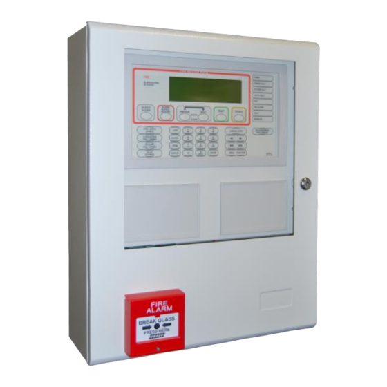
Page 31: Firefinder Plus Control Panel
FireFinder PLUS Control Panel Figure 20: The FireFinder PLUS Control Panel The LCD is used to display abnormal conditions and for interrogation, control and programming activities. When the FACP is in its normal state a default screen is displayed. In access level 2 or higher the backlight shall always be ON. Alarm, Fault and Disable information is accessed through the Main Menu. - Page 32 - Active at access level 1, 2 and 3 Previous and Next controls are used to scroll events on the LCD. The events being displayed depends on the current selected view. When the “SEVERAL ALARMS” indicator is illuminated, then multiple fire alarms are present on the FACP.
- Page 33 - Active at access level 2 and 3 This control is used to disable (and enable) the Alarm Devices. If the indicator is “ON” Steady when any Alarm Devices (including Outputs configured as Alarm Devices) are disabled and flashes if Alarm devices are in fault. Disable has priority over fault. - Active at access level 2 and 3 This control is used to disable (and enable) all the ancillary outputs.
- Page 34 After selecting the Loop number press this button to enter the device number for the device to be interrogated. Press this button followed by a number e.g. ZONE 4 to select the required zone. - Active at access level 2 and 3. Press this button after selecting the Zone number or the Loop and Device numbers to display the state of the device.
-
Page 35: System Indicators
- Active at access level 2 and 3 Used to cancel data into the current field. 10 consecutive entry of this key exits the current access level to the default access level. For example, if the current access level is “2”, 10 consecutive entry of this key will set the current access level to “1”. - Active at access level 2 and 3 Pressing the MENU button will display the main menu on the LCD. - Page 36 - This LED will be illuminated when there is a fault associated with the main or secondary power supply the following conditions constitute a fault. Faults are: ➢ Charger failure ➢ Battery voltage low ➢ Battery missing ➢ HCI missing ➢...
- Page 37 - When this indicator is lit, the FACP is in the fault condition. The fault condition is non latching. Sources of faults are: ➢ Loop devices – missing, type mismatch, out of calibration / out of maintenance range, extra (or unexpected device), device related faults (esp. Hochiki) ➢...
-
Page 38: Functions And Menus
IMPORTANT NOTE: It is strongly recommended that all field programming changes be properly recorded. The Default LCD Display In its normal state the FireFinder PLUS will display a screen similar to that shown below. FIREFINDER 17/10/2013 09:00:00 FIREFINDER PLUS SUBMISSION... -
Page 39: Function Menu And Access Levels
Entering 9999 into the password field; Take note of the 4 digit password number displayed on the screen; then Contact the AMPAC head office and quote the above number; A temporary password will be issued and a new password can then be programmed into the FACP. -
Page 40: The Main Menu
The Main Menu The MAIN MENU is accessed by pressing MAIN MENU Numbering System: denotes the menu structure number 0:ALARMS 1:STAGE 1 ALARMS 2:PRE-ALARMS 3:FAULTS 4:DISABLES 5:WALK TESTS denotes the sub-menu numbering 6:STATUS 7:TOOLS 8:SETUP 9:ABOUT denotes a sub-menu within a sub- SELECT NO. -
Page 41: Pre-Alarms
Pre-Alarms Pressing Displays all Pre-Alarms on the system ZONE: Zone 1 STATUS: PRE-ALARM ‘DATE’ ‘TIME’ ZONE PRE-ALARM DEVICE> AC:2Z ALM:0 PALM:0 FLT:0 DIS:0 Figure 25: The PRE-ALARMS display Pressing the will display the Device Information the screen, pressing the will return it to Zone Information Faults... -
Page 42: Disables
Disables Pressing Displays all Disables on the system. ZONE: Zone 1 STATUS: DISABLE ‘DATE’ ‘TIME’ ZONE DISABLE DEVICE> AC:2Z ALM:0 PALM:0 FLT:0 DIS:0 Figure 29: The DISABLES display Pressing the will display the Device Information the screen, pressing the will return it to Zone Information ... -
Page 43: Status
Status Pressing Displays the Status of the system STATUS MENU 0:LOOPS 1:MODULES 2:I/O 3:BRIGADE 4:SYSTEM 5:AVALUES 6:ADD ONS SELECT NO. AC:2Z ALM:0 PALM:0 FLT:0 DIS:0 Figure 32: The Status Menu (No networking) STATUS MENU 0:LOOPS 1:MODULES 2:I/O 3:BRIGADE 4:NETWORK 5:SYSTEM 6:AVALUES 7:ADD ONS... - Page 44 DISPLAY INPUT/OUTPUT STATUS 0:OUTPUTS 1:INPUTS SELECT NO. AC:2Z ALM:0 PALM:0 FLT:0 DIS:0 Figure 36: The Display I/O Status display DISPLAY OUTPUT STATUS 0:IN A PANEL 1:ON A LOOP SELECT NO. AC:2Z ALM:0 PALM:0 FLT:0 DIS:0 Figure 37: The Display Output Status display Once entered the LCD will then display a description of what that input or output does and its current state.
- Page 45 Network Points: DISPLAY NETWORK POINTS 0:STATUS 1:POWER SUPPLY 2:BRIGADE SELECT NO. AC:2Z ALM:0 PALM:0 FLT:0 DIS:0 Figure 40: Display Network Points Network Points Screens are STATUS: Press, Select network point e.g. Loop Number POWER SUPPLY: Press to display Charger Volts, Battery Detected and Mains OK ...
- Page 46 / ADD-ONS: Is pressed to access MODULE status DISPLAY ADD-ON MODULE STATUS NODE: 000 MODULE (1-32): SELECT ADD-ON MODULE NO. THEN ENTER KEY AC:2Z ALM:0 PALM:0 FLT:0 DIS:0 Figure 44: Add on Module status Page 39...
-
Page 47: Tools
Tools Pressing allows for the Testing of the following selected fields TOOLS MENU 0:ALARM 1:FAULT 2:LAMP SELECT NO. AC:2Z ALM:0 PALM:0 FLT:0 DIS:0 Figure 45: The TOOLS menu Pressing brings up a further detailed selection sub-menu for an Alarm tests. ALARM TEST 0:ZONE 1:DEVICE... -
Page 48: Setup
Setup Pressing Displays the setup for sounders, Zone Delay and Printer SETUP MENU 0:SOUNDER 1:ZONE DELAY 2:PRINTER 3:LANGUAGE SELECT NO. AC:2Z ALM:0 PALM:0 FLT:0 DIS:0 Figure 48: The SETUP menu brings up a further detailed selection sub-menu for Sounder O/P’s. Pressing SOUNDER MENU 0:SOUNDER ENABLE... -
Page 49: About
About Displays the panel’s application software version number and the title information. Title Pressing information could be company name, contact information and so on. ABOUT MENU VERSION#:1.01.00.AS7240 AMPAC TECHNOLOGIES AC:2Z ALM:0 PALM:0 FLT:0 DIS:0 Figure 52: The About menu... -
Page 50: The Function Menu
The Function Menu The FUNCTION MENU is accessed by pressing button. A prompt will ask for a PASSWORD if the control panel is not currently active. Using the keypad key in the Level 2 or 3 PASSWORD. LEVEL III MAIN FUNCTIONS 0:DATE 1:TIME 2:DAY/NIGHT... -
Page 51: Day/Night
Day/Night Press The DAY-NIGHT SETTINGS screen will appear. Time entry is the same as setting the “Time” facility. Note this Function is available at Access Level 3 only. Press To enter the DAY ON time. Press To enter the NIGHT ON time. ... -
Page 52: Tests
TESTS Press to access the TESTS menu. Note this is an Access Level 3 function only. TESTING MENU 0: WALK TEST 1:LOOP TEST 2: DEVICE LED TEST SELECT NO. AC:3Z ALM:0 PALM:0 FLT:0 DIS:0 Figure 58: The Testing Menu ... - Page 53 Press To display the Manual I/O Control menu MANUAL I/O CONTROL 0: INPUT 1 :OUTPUT 2: REMOVE ALL MANUAL CONTROL SELECT NO. AC:3Z ALM:0 PALM:0 FLT:0 DIS:0 Figure 60: The Manual I/O Control Menu Manual I/O control allows the technician to turn ON or OFF inputs and outputs off a device to facilitate testing or isolation of plant during maintenance.
-
Page 54: Global
Global Press To display the Global Output Control menu (These operates across all panels on the network) GLOBAL OUTPUT CONTROL 0:FWRE OUTPUT 1:FARE OUTPUT 2:WARNING SYSTEM OUTPUT SELECT NO. AC:3Z ALM:0 PALM:0 FLT:0 DIS:0 Figure 63: The Global Output Control Menu Press ... -
Page 55: Passwords (Level Iii)
Passwords (Level III) Press While in the Main Functions menu and enter the Level III Password if in Access Level II or, if in Access Level III to display the Password Menu. PASSWORD MENU 0: ADD PASSWORD 1 :DELETE PASSWORD 2: DELETE ALL PASSWORDS SELECT NO. -
Page 56: Programming
Programming Press To display the Level III Programming Menu. ON SITE PROGRAMMING MENU 0: CONV ZONE 1 :DEVICE 2:INPUT 3: OUTPUT 4: PANEL BASED MCP 5:SUB ADDRESS 6:ZONE PROGRAMMING SELECT NO. AC:3Z ALM:0 PALM:0 FLT:0 DIS:0 Figure 65: Programming Menu 8.9.1 Conv (Conventional) Zone ... -
Page 57: Device
EDIT Z CONFIGURATION CONFIG: LATCHING Use < or > to change alarm setting AC:3Z ALM:0 PALM:0 FLT:0 DIS:0 Figure 68: Zone Configuration Latching / Non-latching to change the setting Configuration settings are Latching, Non-Latching, AVF, Self Reset ( 0 to 99 seconds ). After setting the Configuration the ZONE I/O GROUPS are programmed. -
Page 58: Input
4. Set / Edits and enables / disables the day/night settings then. Press 5. Allocates / Edits the Loop and Devices Groups. After scrolling through the groups a prompt tells the operator to press to confirm the changes. 8.9.3 Input ... - Page 59 EDIT ZONE: 1 DESC STRING DESCR<MY ZONE 1 DESCRIPTION ALPHA KEYS ARE ACTIVE [USE>> TO EDIT NEXT FIELD] AC:3Z ALM:0 PALM:0 FLT:0 DIS:0 Figure 70: Zone Programming - Description Press the key to edit the next field (Day Night Settings). EDIT ZONE: 1 DAY NIGHT SETTINGS DAY_NIGHT ENABLE:...
-
Page 60: Extra Devices Detected
ZONE FAULTS 1 of 1 Figure 77: Resolving a Mismatch Self Learn is enabled / disabled in the EEPROM programming. If enabled FireFinder PLUS has the ability to detect extra or missing modules or devices, (that is devices or modules that have been added or removed) or there has been a change of the type of module or device. -
Page 61: Incoming Fire Alarm Signal
Incoming Fire Alarm Signal ➢ Will operate the red common LED fire indicator ➢ Will display location of fire alarm origin on the LCD ➢ Will activate external alarm. ➢ Will activate the internal FACP buzzer. ➢ Will activate any ancillary equipment so programmed. ➢... -
Page 62: Accessing A Loop, Device Or Zone
Accessing a Loop, Device or Zone LOOP OR DEVICE ➢ From the default display, press ➢ Enter the loop number you wish to interrogate then press ➢ Press the button for the device number. ➢ Press the button if you wish to access a range of devices on the loop, ➢... -
Page 63: Modem / Programming / Debug Interfacing
Figure 80: FireFinder PLUS Debug Cable Connections Note: the DB9F to DB9F cable is not sensitive to which end is plugged in to the FireFinder PLUS or serial port of the PC or vice versa. The connections between the PC/Modem and the panel are crossed. i.e. TD connects to RD. -
Page 64: Expanding The Facp With Compatible Firefinder Plus Boards
Expanding the FACP with Compatible FireFinder PLUS Boards 12.1 Ancillary Services The FACP has been designed such that detectors and/or call points, in addition to giving an alarm and calling the fire brigade, will close or open circuits of ancillary services by means of relays or similar devices. -
Page 65: Expansion Board
12.3 Expansion Board The Expansion Connection Board (BRD86FEPB) is used to increase the capacity of the controller from 4 Slave CPU’s to 8 allowing Loops 5 – 8 to be configured. Connection from the Controller to the Expansion Board, which must be mounted within 200mm of the Controller, is made via a 20 way flat cable Slave CPU number 5 is an integral part of the Expansion Board, only Slave CPU’s 6 (CN2), 7 (CN3 and 8 (CN4)are plug ins. -
Page 66: Zone Conventional Board
12.4 8 Zone Conventional Board This board (BRD43EZC) has 8 conventional zones. Up to 999 zones max may be configured. The zones may be used in panel programming and Input / Output programming. Note 1: Each Zone circuit MUST be terminated with either a; ➢... -
Page 67: Zone And 32 Zone Indicator Modules
12.5 16 Zone and 32 Zone Indicator Modules This module (BRD43ZAMC) has 32 bi-coloured LED’s which can be used to display the status of up to 32 individual Zones or 16 Zones with dual LEDs. The zone numbers assigned to each LED are configurable and the LED’s will operate in the following manner for the respective zone statuses: ZONE STATUS LED STATE... -
Page 68: Way Switch And Indicator Module
12.6 8 Way Switch and Indicator Module This card (BRD25GIB-B) has 8 switch inputs and 8 LED indicator outputs. The switch inputs and LED outputs may be used in Input Output programming. The switches are configurable as either momentary or toggle switches. When configured as momentary pressing the button once will cause an event to occur as programmed in I/O and the LED’s can be programmed to operate as an output. -
Page 69: Zone Disable And Indicator Module
12.7 Zone Disable and Indicator Module This module (BRD25GIB-F) has 8 switch and dual LED groups. Each group can be associated to a single Zone. The switch is used to disable the associated zone, while the LEDs are used to indicate the zone status. -
Page 70: Way Input Board
12.8 16 Way Input Board The 16 Way Input Board (BRD25SIP) makes provision for 16 voltage free contacts to be terminated to 16 optically coupled inputs. Its application is primarily for the monitoring of controlled ancillary equipment or to initiate an action / event due to a change of state from what is accepted as the norm. ... -
Page 71: Way Relay Board
12.9 8 Way Relay Board The Relay Board (BRD25EWRB) provides 8 programmable relays with 30VDC 1 Amp voltage free change over contacts for control or monitoring purposes and comes fitted for internal or external FACP use. The functionality and programming of the relays is similar to the relays on the main board of the FACP. By default the relays default to Common Alarm functionality. -
Page 72: Remote Relay Board
12.9.2 Remote Relay Board In the remote version the Comms In and Out Terminal Block TB9 is cabled to the RS485 Comms terminal block TB1on the Communications Extender Board (see section 5.12) and can be installed up to 1.2kms from the FACP. ... -
Page 73: Way Sounder Board
12.10 8 Way Sounder Board The Sounder Board (BRD25SOP) expands the number of sounders that can be used on an FACP by 8. Each output is of a solid state design, rated at 24VDC / 750mA and requires a 10KΩ End of Line (EOL) resistor regardless of whether or not a sounder is wired to the circuit. -
Page 74: Way Fire Fan Module
12.11 4 Way Fire Fan Module The Fire Fan Module (BRD25FCB) has four (4) separate fan controls each having an On, Auto and Off function switch and a set of three (3) monitoring LED’s. The LED’s indicate the status of the equipment e.g. -
Page 75: Way Fan Termination Board
12.12 4 Way Fan Termination Board The Fan Termination Board (BRD25FTB) interfaces between the Fire Fan Module and the plant/equipment it controls via the 24 Volt 250mA Start, Stop, current limited, relay outputs and monitor inputs. Programmable monitoring of the field equipment is achieved using 0 volts as an input level to indicate run, fault and stop conditions of that equipment. -
Page 76: Bargraph Display Card
The Bargraph display card (BDC) provides a smoke obscuration bargraph, alarm indicators, a reset and disable facility for a Pro-Sens fitted with an Ampac version of an APID fitted. The BDC supports two detectors, which can be located in the same Pro-Sens unit or separate Pro- Sens units. -
Page 77: Communications Extender Board
Figure 98: Communications Extender Board PCB Layout 12.15 SmartTerminal SmartTerminal connects to the FireFinder Plus Fire Alarm Control Panel (FACP) via the RS485 Communications Extender Board. Generally it is designed to be used anywhere where the status of the FACP is required to be monitored by local personnel and limited control is required. It can also be tailored as a Nurse Fire Station (NFS). -
Page 78: Mechanical
12.15.2 Mechanical SmartTerminal is supplied in an ABS cabinet and consists of; ➢ The Main Card, with all controls and indicators mounted directly onto it ➢ 1 X Termination Board ➢ 2 X ABS door keys ➢ 2 X 003 Enable / Disable keys ➢... -
Page 79: Installation & Cabling
12.15.3 Installation & Cabling SmartTerminal is connected to the FACP as shown below. SHIELDED COMMS CABLE Main Panel TO NEXT SmartTerminal RS485 OUT or LED MIMIC SHIELD +24VDC CN20 C O M RJ45 +24V CN18 CABLE COMMUNICATIONS EXTENDER BOARD RN20 RN17 27VDC FACP MAIN... -
Page 80: Operation
12.15.5 Operation The operation of SmartTerminal can be considered to be in one of three states, these are; Power up - when the SmartTerminal is initialising Normal - when the SmartTerminal address has been set and is communicating with the FACP, reporting normal / abnormal conditions and controlling the FACP via the front panel controls Fault where the SmartTerminal is in fault and/or is unable to communicate with the FACP. -
Page 81: Smartterminal Controls And Indicators
12.15.6 SmartTerminal Controls and Indicators All controls, except for the controls Enable / Disable Keyswitch, are of a momentary push button style and operate in exactly the same way as does the FACP itself. Figure 102: SmartTerminal Front Panel Layout 12.15.7 SmartTerminal Screen Format There are 3 events that can be reported and displayed by SmartTerminal. - Page 82 Fault: If configured the screen format for reporting loop / device / zone fault condition is: Zzzz FAULT <zone descriptor> <date> <time> CONTROL* FAULT XXX OF XXX DEVICE► Note: The fault types only relate to devices. In the event of a loss of communications, for a period of greater than 15 seconds the SmartTerminal will default to the No Communications screen.
- Page 83 Normal / Default: The format for reporting that everything is normal is: <DATE> <TIME> ACCESS LEVEL: 1 <USER DESCRIPTOR LINE 1> <USER DESCRIPTOR LINE 2> <SYSTEM STATUS> <DAY MODE-MAN I/O> The screen is only displayed when there are no alarms, fault or disables on the panel. The highest priority current system status will be displayed and can be one of the following listed in order of highest to lowest priority: “SYSTEM ALARM”...
-
Page 84: Agent Release Control
12.16 Agent Release Control Agent Release control consists of an Agent Release Module, Termination Board and an optional Local Control Station. 12.16.1 Operation Introduction The Agent Release Module and Termination Board communicate with the FACP via the RS485 multi- drop bus. The Local Control Station communicates only with the Termination Board via a separate RS485 bus. - Page 85 Note: A “manual release” can still be initiated in “auto mode” but the LCS “Inhibit” control WILL NOT inhibit / abort the agent release sequence. Single Zone Activation, the following discharge sequence is executed; ➢ Automatic Activation LED is illuminated on the Agent Release Module and Local Control Station.
- Page 86 Note #1: The common fault indicator on the Agent Release Module and Local Control Station is illuminated for any Fault condition. Note #2: For a pressure switch fault, low pressure switch fault, lock-off valve fault, stage 1 output fault, stage 2 output fault and interlock fault, the FACP will signal the brigade. ...
-
Page 87: Agent Release Module
12.16.2 Agent Release Module The Agent Release Module controls and monitors all the requirements for agent release. Top Module & PCB TERMINATOR LINK Securing Clips ADDRESS Fit EOL Termination SWITCH S W 2 Link 1 if Last Module on Comms Bus INHIBIT RS485 Control RS485 Control... -
Page 88: Local Control Station
12.16.3 Local Control Station The Local Control Station is supplied fitted into an IP40 rated enclosure and has the same indicators and Manual Release switch as the Agent Release Module within the Fire Alarm Control Panel (FACP) but no Agent Select button or Service Inhibit keyswitch. The Comms line is RS485 and is cabled to the Agent Termination Board. - Page 89 Agent Release / LCS Indicators There are 12 indicators on both the Agent Release Module and Local Control Station. They are; MANUAL (Red) Illuminated when a manual release sequence has commenced. A Manual ACTIVATION release sequence can only be started by activating the manual release at the FACP or LCS. The indicator is extinguished by activating RESET on the FACP.
- Page 90 RESERVE AGENT (Yellow) Illuminated when the “Reserve Agent” is selected. Local Control Panel Inhibit The agent inhibit switch has an internal lamp fitted with yellow lens. Illuminated when the inhibit switch is activated at the FACP or any of the LCS’s. Buzzer (located at the FACP) The Buzzer sounds;...
-
Page 91: Agent Release Termination Board
12.16.4 Agent Release Termination Board INPUTS SYST. STAGE2 RELEASE LCS CABLE STAGE1 SIG+ + L.PSW- 0VDC MAIN RESV N/0 C O M + N/0 C O M +24VDC SCRN SIG- + LOCK- C OM + PSW - MONITORED FIRED INOP + - Outputs are Monitored RS485 Control Comms In... -
Page 92: Interface Wiring
12.16.5 Interface Wiring Monitored Inputs TB2 1 & 2 Solenoid & Metron This input relies on N/O or N/C relay contacts used in conjunction with 22K EOL and 4K7 series resistors. The type of agent release mechanism and contacts used has to be set in the Programming Menu for the input to function as per the manufacturers specifications and be in accordance with the relevant Standard. -
Page 93: Warning Signs
12.16.6 Warning Signs Introduction The Ampac Warning Signs provide clear, visual and audible indication of an alarm event and are designed for use with fire detection and alarm systems which may incorporate agent release capability. The display may also be customised as required to cater for a variety of applications. - Page 94 The Warning Sign can be configured to illuminate in two ways. For voltage reversal, 2 wire applications and for use with the Ampac Agent Release module, refer figure 1. For common positive, switched negative 3 wire applications, refer figure 2.
- Page 95 N/O COM Figure 113: Two Wire Voltage Reversing Connection (Ampac Agent Release Module) Page 88...
- Page 96 Figure 114: Polarised 3 Wire Connection Page 89...
-
Page 97: Occupant Warning Systems
Input 4 latching). (Default = External fault input) Note: The digital inputs are not necessary when using the Front Panel Switch & Indicator board in the FireFinder Plus. The Relays are rated to 1A and function as follows: Page 90... -
Page 98: Front Panel Switch And Indicator Module
Strobe The output is monitored and requires 10kΩ 5% 1/3Watt EOL. Allows for 8 x Ampac Xenon Strobes (208-0011) or 40 x Ampac LED strobes 4107-1005/6) The 100V line Output functions as follows: Provides an isolated 100VAC Audio Output. Supports up to 3 branches. -
Page 99: Panel Interfacing
12.17.3 Panel Interfacing Page 92... -
Page 100: Printer
12.18 Printer Specifications ➢ Printing method: directed impact dot matrix ➢ Interface: 8 bit parallel interface ➢ Printing mechanism: 4/6 pin shuttle ➢ Interface port: 26 PIN flat plug 12.18.1 Indicators and Buttons The front panel has an LED indicator and two buttons SEL (SELECT), LF (LINE FEED). Figure 118: Printer Front Panel Layout (Front Cover Closed / Open) Indicator When the 3 colour LED indicator is illuminated;... -
Page 101: Maintenance
Self-Test Mode With power applied (green LED illuminated) push the SEL button. This will turn off the LED. Press and hold in the LF button, then press the SEL button again and the printer will enter the Self Test mode. Self-test will print out all the valid characters in the character sets. - Page 102 Figure 120: Head Mechanism Rotation and Paper Roll Removal / Insertion Take out the empty paper roll and roller Put the new paper roll onto the paper roller and replace as shown above. Connect to the power supply. Press the SEL button to take the printer Off Line, (LED is off). Press the LF button, (paper feed).
-
Page 103: Printer Connections And Jumpering
12.18.3 Printer Connections and Jumpering Mounted on the back of the printer mechanism is the PCB that carries the; ➢ Connectors for interconnection to the Main Board, ➢ Jumper links required to set the programmed print modes; and ➢ Printer 5 volt DC Power Supply. Figure 121: PCB Layout Jumper Settings Designator... -
Page 104: Expanding The System - Networking
Expanding the System – Networking Expanding the system can be achieved in various ways and requires the use of boards specifically designed for communications purposes and boards that actually expand the system. 13.1 Networking When FACP’s are connected to each other they form a “NETWORK“. Individual FACP’s in the Network are referred to as NODES. - Page 105 PANEL 1 16 Way BACKLIGHT RESET MAIN BOARD EXPANSION CN17 MODULE CN20 SLAVE 4 SLAVE 3 SLAVE 2 CN100 CN14 MAIN BOARD INTERFACE CN13 CN15 CN11 POWER 27VDC NETWORK INTERFACE SLAVE CPU 4 SLAVE CPU 3 SLAVE CPU 2 CARD BIAS CN23 RS485...
-
Page 106: High Level Interfacing
Software The Serial/USB port supports the following protocols:- HLI – Functionality matches the FireFinder PLUS panel which supports text or positive ack protocol. Configurable attributes are: logical output, physical output, alarm output, pre-alarm output, fault output, isolate output and descriptors... - Page 107 NODE 1 RS 232 RS 485 CN17 MAIN CONTROL BOARD CH16 CH15 S H D RJ45 CN20 SERIAL CN13 CN14 PARALLEL CN15 CN11 FACP COMMS CN18 RS485 LOOP MODBUS HLI CONTROLLER C OMMS +2 7 V FACP RN20 RN17 FACP 0V +2 7V ADDRESS M SB...
-
Page 108: High Level Interface Expander (Brd43Hli)
RS232 or RS422 SmartView is an extensible web-based, client server application whose primary role is dedicated to the monitoring and reporting of Ampac’s fire detection system events. SmartView provides clear and precise alarm information using graphical and text formats. Page 101... -
Page 109: Certification Information
Certification Information The FireFinder Plus is designed and manufactured by: AMPAC TECHNOLOGIES PTY LTD 7 Ledgar Rd Balcatta 6021 Western Australia 61-8-9242 3333 FAX: 61-8-9242 3334 Manufactured to: Certificate of Compliance Number: Equipment Serial Number: Date of Manufacture: Page 102... -
Page 110: Maintenance And Troubleshooting Chart
16.1 Maintenance The FireFinder PLUS FACP should be maintained so as to comply with all standards / regulations applicable to the country and location it has been installed. Failure to do so could put at risk compliance and the integrity of the system. As a minimum it is recommended the following be used as a guide to periodic maintenance especially if there is an absence of standards regulations. -
Page 111: Troubleshooting Firefinder Plus
Incorrect Password entered Can not access Function menu Ring AMPAC and directions will be given to provide you with a temporary code Forgotten password A 1.8k Ohm resistor must be placed in An Analogue Fault occurs when series with the switch contacts. -
Page 112: Compatible Devices
Compatible Devices Auto AMPAC Displayed Type Type Learn Device Type Type Code chars) Desc Default Optical XP95 Optical XP95 PHOTO PHOTO XP95 Optical with base sounder XP95 PHOTO + SNDR PHOTO XPander Optical XPANDER PHOTO PHOTO S90 Optical S90 PHOTO... - Page 113 Auto AMPAC Displayed Type Type Learn Device Type Type Code chars) Desc Default Manual Call Points S90 MCP S90 MCP 11Fh Discovery MCP DISC MCP XP95 MCP XP95 MCP XPander MCP XPANDER MCP XP95 Mini switch monitor with interrupt...
-
Page 114: Address Setting
Address Setting BINARY ADDRESS SETTING (APOLLO) SERIES XP95 - ADDRESS DATA DIL SWITCH: ON = 1 OFF = 0 ADDRESS TAG FOR DETECTORS (I/O DEVICES) DIL switch setting DIL switch setting DIL switch setting DIL switch setting DIL switch setting Address 1234567 Address 1234567 Address 1234567... -
Page 115: Glossary Of Terms
Glossary of Terms ACF: ANCILLARY CONTROL FACILITY ACKD: ACKNOWLEDGED AHU: AIR HANDLING UNIT ALM: ALARM AVF: ALARM VERIFICATION FACILITY AZF: ALARM ZONE FACILITY AZC: ALARM ZONE CIRCUIT RELAY COMMON CONTACT (WIPER) CIC: CONTROLLER INTERFACE CARD CONNECTOR CPU: COMMON PROCESSOR UNIT DGP: DATA GATHERING POINT EARTH:... -
Page 116: Definitions
Alarm Verification Facility (AVF) - that part of the FACP, which provides an automatic resetting function for spurious alarm signals so that they will not inadvertently initiate Master Alarm Facility (MAF), or ACF functions. Using ConfigManager PLUS prior to downloading to the FireFinder PLUS sets this option Alarm zone - the specific portion of a building or complex identified by a particular alarm zone facility. -
Page 117: Specifications
Specifications Metal SP1M (Europe Metal SP8X Only) Mechanical 845 (H) x 518.5 (W) x 505 (H) x 407 (W) x 150 173(D) Dimensions Cabinet: ( mm ) Includes window outer door Material 1.2mm Mild Steel 1.2mm Mild Steel Environmental Temperature: -5ºC to + 40ºC Humidity: 0% to 95% non-condensing... - Page 118 Metal SP1X Metal SP16X Mechanical 505 (H) x 407 (W) x 150 1200 (H) x 625 (W) x 240 Dimensions Cabinet: ( mm ) Includes window outer Includes window outer door door Material 1.2mm Mild Steel 1.2mm Mild Steel Environmental Temperature: -5ºC to + 40ºC Humidity:...
-
Page 119: Quick Reference Guide
QUICK REFERENCE GUIDE Page 112... -
Page 120: Statement Of Compliance
Statement of Compliance Please PRINT Name of Building: Address: I/We have installed in the above building an alteration to the system manufactured by, OR a system manufactured by. (Name of Service Provider) The system is connected to monitoring service provider by a Permanent , Non-Permanent connection Date of connection... - Page 121 I/We Print Name/s Hereby certify that the installation has been thoroughly tested from each actuating device and that a test of the transmission of the alarm signal to the monitoring service provider has been satisfactorily carried out. I/We further certify that the whole system and all components called up in Clause 1.3 in connection therewith are installed entirely in accordance with the current requirements of AS 1670.l, - Except with regard to the following details which have already been approved, approval attached.
-
Page 122: Installation Details
23.1 Installation Details # Indicate with a number in brackets the number of actuating devices in concealed spaces. * Add addressable loop number in brackets where applicable. Zone Number and Type of Actuating Devices Alarm Thermal Fire Flame Actuating Zone Other Devices Smoke CO... -
Page 123: Commissioning Test Report
Commissioning Test Report This FireFinder PLUS Fire Alarm Control Panel is installed at: Company Name Street Suburb State Country Post Code (Company Name & Installation Address ) Owner or Owners' Authorized Representative: Company Name Street Suburb State Country Post Code... -
Page 124: Procedure
The following tests are the minimum that shall be performed when commissioning a system using the FireFinder PLUS Fire Alarm Control Panel. Supplements to these tests may be added by way of attachments or notation (using waterproof ink) to this documentation. If supplements or tests are added reference to them shall be made at an appropriate point on this document. - Page 125 including that the receiver responds to signals from an actuating device for alarm, tamper, low standby power signals and gives a fault signal when the supervisory signal condition is absent. (j) Operation of fault and alarm signals: Fault and alarm conditions ...
- Page 126 (ii) There are no ‘blind’ spots in the area protected. (iii) Detectors are rigidly fixed. (iv) Detector lenses are clean and adequately protected from dust and extraneous radiation sources. ...
- Page 128 UNCONTROLLED DOCUMENT NOTE: Due to AMPAC’s commitment to continuous improvement specifications may change without notice.
Need help?
Do you have a question about the FireFinder PLUS and is the answer not in the manual?
Questions and answers