Table of Contents
Advertisement
Quick Links
Advertisement
Table of Contents

Related Manuals for saia-burgess PCD3 Series

Summary of Contents for saia-burgess PCD3 Series
- Page 1 Hardware Manual for the PCD3 Series Document-No. 26/789; Version E5; 31.01.2005...
-
Page 2: Table Of Contents
3.13.5 Backup/restore of RAM texts/DBs at run-time ..........3-24 3.14 Hardware clock (Real Time Clock) ..............3-27 3.15 Hardware watchdog ..................3-27 3.16 Software watchdog ..................3-29 3.17 Interrupt inputs ....................3-30 3.17.1 Basics ......................3-30 Hardware Manual for the PCD3 Series│Document 26/789; Version E 5│31.01.2005... - Page 3 5.3.1 PCD3.A200, 4 relay contacts, type “NO”, with contact protection ....5-30 5.3.2 PCD3.A210, 4 relays with “normally closed” contacts, with contact protection ...................... 5-32 5.3.3 PCD3.A220, 6 relay contacts, type “NO”, w/o contact protection ....5-34 Hardware Manual for the PCD3 Series│Document 26/789; Version E 5│31.01.2005...
- Page 4 Icons ....................... 9-1 Definitions of serial interfaces ................. 9-2 9.2.1 RS 232 ......................9-2 9.2.3 TTY/current loop ................... 9-4 Order details ....................9-5 Address of SAIA-Burgess Controls AG ............9-8 Hardware Manual for the PCD3 Series│Document 26/789; Version E 5│31.01.2005...
-
Page 5: Document History
, and Siemens ® are registered trademarks of Siemens AG. Technical changes are subject to the state of technology. Saia-Burgess Controls AG, 2004. © All rights reserved. Published in Switzerland Hardware Manual for the PCD3 Series│Document 26/789; Version E 5│31.01.2005... -
Page 6: Graphical Index
The graphical index singles out some highlights from the Hardware manual for the PCD3 Series, and allows you to click on the text frames or directly on a component/ connector to jump straight to the corresponding section. The facility to jump to any section from the table of contents is still to be completed. -
Page 7: Orientation Guide
Addressing and cabling of rows of controllers Details of hardware, software, configuration, maintenance and troubleshooting are described in separate sections. The Appendix contains an explanation of the icons used, and the company address. Hardware Manual for the PCD3 Series│Document 26/789; Version E 5│31.01.2005... -
Page 8: Planning An Application
● If the application is mounted in multiple rows, the restricted length of cable means that only three LIOs (1x PCD3.C200 + 2x PCD3.C100) may be mounted in one row Hardware Manual for the PCD3 Series│Document 26/789; Version E 5│31.01.2005... - Page 9 Connecting material for this arrangement: n x PCD3.K010 connectors between PCD3 module holders For all arrangements: After every five PCD3.C100 module holders, insert a PCD3. C200 base unit as an I/O bus amplifier Hardware Manual for the PCD3 Series│Document 26/789; Version E 5│31.01.2005...
- Page 10 Calculate the number of terminal blocks required for the I/Os, and order separately. Screw or spring clamp terminal blocks can be ordered as required. Not all modules require the same type of socket connection. Hardware Manual for the PCD3 Series│Document 26/789; Version E 5│31.01.2005...
-
Page 11: Cabling
● With lines laid outside, the shield must have adequate current-carrying capacity and be earthed at both ends. ● The surge conductors should be installed at the input to the switching cabinet. Hardware Manual for the PCD3 Series│Document 26/789; Version E 5│31.01.2005... -
Page 12: Addressing And Cabling Rows
Address 255 is reserved for the watchdog relay. Modules that use this address must not be installed in module position 16. For more details, please refer to the section on “Hardware watchdog”. Hardware Manual for the PCD3 Series│Document 26/789; Version E 5│31.01.2005... -
Page 13: Labelling Module Holders And Modules
2-L4 3-L3 3-L4 Frontview Frontview All PCD3 module holders and the PCD3.K106 extension cable are provided with a matching set of labels for additional markings. 1008 4 310 8686 0 Hardware Manual for the PCD3 Series│Document 26/789; Version E 5│31.01.2005... -
Page 14: Pcd3.Mxxx0 Classic Cpus And Expansion Housings
PCD3 controllers on the Profibus ● Multi-protocol operation: The new Saia ® PCD3 controllers and Saia ® PCD3 RIOs support Profibus-DP and S-Net on the same socket ● Continuity and security of investment: Hardware Manual for the PCD3 Series│Document 26/789; Version E 5│31.01.2005... -
Page 15: General Technical Details
In all other mounting positions, a reduced temperature range of 0..+40 °C applies Storage temperature -20...+85 °C (DIN 40040, class HS) Relative humidity 30...95% without condensation (DIN 40040, class F) Hardware Manual for the PCD3 Series│Document 26/789; Version E 5│31.01.2005... -
Page 16: System Resources
Cyclic organization blocks 0...15 Main program elements (COB) Exception/system-dependent 0...31 Called from the system organization blocks (XOB) Program blocks (PB) 0...299 Sub-programs Function blocks (FB) 1000 0...999 Sub-programs with parameters Hardware Manual for the PCD3 Series│Document 26/789; Version E 5│31.01.2005... -
Page 17: Computation Ranges For Count Types
LD command, and cannot be used in instructions instead of registers 1) The number of timers configured should be only as many as required, to prevent unnecessary CPU loading Hardware Manual for the PCD3 Series│Document 26/789; Version E 5│31.01.2005... -
Page 18: Pcd3 Cpus
4) The period given is a buffer time; it is dependent on the ambient temperature (a higher temperature means a shorter buffer time) 5) The 1kHz applies with a pulse/pause ratio of 1:1 and refers to the total frequencies of the two inputs Hardware Manual for the PCD3 Series│Document 26/789; Version E 5│31.01.2005... - Page 19 With a hub USB 2.0 the Download is two times fasterl. Can also be used as a serial data port, e.g. to connect a terminal; but this hampers commissioning and troubleshooting with the debugger Hardware Manual for the PCD3 Series│Document 26/789; Version E 5│31.01.2005...
-
Page 20: Block Diagram For Pcd3.Mxx0
When the power is switched on, no operations (such as moving jumpers or (un)plugging I/O modules) should be attempted. To prevent loss of data, batteries should be changed with the power switched on. Hardware Manual for the PCD3 Series│Document 26/789; Version E 5│31.01.2005... -
Page 21: Hardware And Firmware Versions For The Pcd3.Mxxx0
1) A modem connection is not always reliable. A modem may become blocked in such a way that remote access is no longer possible. In such cases, an on-site visit will be necessary. Other connection options are preferable Hardware Manual for the PCD3 Series│Document 26/789; Version E 5│31.01.2005... -
Page 22: Expansion With Pcd3 Components
For decentralized expansion using profibus, the PCD3 RIO (remote I/O) modules can be used: The maximum number of I/Os is dependent on the controller being used: When selecting I/O cassettes, ensure that the internal 5V and +V supply is not overloaded. Hardware Manual for the PCD3 Series│Document 26/789; Version E 5│31.01.2005... -
Page 23: Mounting Cpus And Module Holders
4 positions (labelled 0, 1, 2 and 3) PCD3.Mxxx0,C100/C200/T760 ● 2 positions (labelled 0 and 1). The PCD3.C110 can only be used as the last module holder in the bus 3-10 Hardware Manual for the PCD3 Series│Document 26/789; Version E 5│31.01.2005... -
Page 24: Mounting Position And Ambient Temperature
0°C to 55°C. In all other positions, air convection works less well, and an ambient temperature of 40°C should not be exceeded. Dimensions PCD3.M5xx0 PCD3.M3xx0 67.3 28.5 63.8 125.8 3-11 Hardware Manual for the PCD3 Series│Document 26/789; Version E 5│31.01.2005... - Page 25 Saia-Burgess Controls Ltd. PCD3.Mxxx0 Classic CPUs and expansion housings Dimensions PCD3.C100/C200/T76x PCD3.C110 3-12 Hardware Manual for the PCD3 Series│Document 26/789; Version E 5│31.01.2005...
-
Page 26: Power Supply And Connection Plan
PCD3.E1xx, E5xx, E6xx, A2xx, A4xx, B1xx, G4xx PCD3.W1xx, W2xx, W3xx, W4xx, W5xx, W6xx PCD3. H1xx , H2xx , H3xx PCD7.D2xx These modules must be connected to a smoothed 24 VDC supply 3-13 Hardware Manual for the PCD3 Series│Document 26/789; Version E 5│31.01.2005... -
Page 27: Earthing And Connection Plan
Minus terminal or via the earthing bar. All Minus connections are linked internally. For problem-free operation, these connections should be reinforced externally with short wires of 1.5 mm 3-14 Hardware Manual for the PCD3 Series│Document 26/789; Version E 5│31.01.2005... -
Page 28: Internal Power Supply
Run, Run conditional, Run with error, Run cond. with error, Stop, Stop with error, Halt and System Diagnostics The display uses the LEDs shown below: ��������� ���� ����� ��� ���� ����� �������� ���� ����� ���� 3-15 Hardware Manual for the PCD3 Series│Document 26/789; Version E 5│31.01.2005... - Page 29 • No communication module on an S-Bus PGU or Gateway Master port System diagnostics Reset The Reset state has the following causes: • Supply voltage too low • Firmware not starting up 3-16 Hardware Manual for the PCD3 Series│Document 26/789; Version E 5│31.01.2005...
-
Page 30: Connections To The Pcd3.Mxxx0
Int0 2 interrupt inputs or 1 fast counter Int1 Watchdog +24V Power supply RS485 terminator switch Switch Designa- Explanation position tion left without termination resistors right with termination resistors 3-17 Hardware Manual for the PCD3 Series│Document 26/789; Version E 5│31.01.2005... -
Page 31: Partitioning Options For User Memory
(16384 instead of 384), take up less space (only 4 bytes instead of 8 bytes per element, but NB, 8 bytes instead of 3 for the header) and the access time is substantially shorter. Example of manual partitioning: 3-18 Hardware Manual for the PCD3 Series│Document 26/789; Version E 5│31.01.2005... -
Page 32: Data Storage In Case Of Power Failure
flat or shows an interrupt the battery is missing We recommend changing the batteries with the PCD attached to the power supply, to avoid any loss of data. 3-19 Hardware Manual for the PCD3 Series│Document 26/789; Version E 5│31.01.2005... -
Page 33: Backup Of The User Program
If it transpires when the PCD3 is started up that one of the RAM memories has been corrupted (e.g. after a power failure with a flat or missing battery), the application is automatically copied to the PCD. With test 400H this can be controlled. 3-20 Hardware Manual for the PCD3 Series│Document 26/789; Version E 5│31.01.2005... -
Page 34: Program Backup And Restore With Onboard Flash
PG5 can be used to write a valid program to the CPU from the onboard flash. On the PCD3.M5xx0, 256 kBytes must be configured for this. The flash card must not be plugged in. 3-21 Hardware Manual for the PCD3 Series│Document 26/789; Version E 5│31.01.2005... -
Page 35: Program Backup And Restore With Flash Card (Pcd3.M5Xx0 Only)
Re-connect supply voltage to the target controller; the LEDs will flash while the program is copied from the flash card Re-insert battery module within 1 minute, to avoid the “battery fail” error message Wait until the controller has restarted 3-22 Hardware Manual for the PCD3 Series│Document 26/789; Version E 5│31.01.2005... -
Page 36: 3.13.4 Download Backup Option
flash after every download. This can be found in the Project Manager, under Tools, Options, Download: The same option window can be called up when downloading, as follows: 3-23 Hardware Manual for the PCD3 Series│Document 26/789; Version E 5│31.01.2005... -
Page 37: 3.13.5 Backup/Restore Of Ram Texts/Dbs At Run-Time
Within the maximum number of write cycles, a text/DB can be stored any number of times, without the flash card becoming over-full. 3-24 Hardware Manual for the PCD3 Series│Document 26/789; Version E 5│31.01.2005... - Page 38 The processing time for the instruction may be several 100 ms. For this reason, the instruction must not be invoked in XOB 0 (XOB for a power failure) or during time-critical processes. 3-25 Hardware Manual for the PCD3 Series│Document 26/789; Version E 5│31.01.2005...
- Page 39 Too many texts/DBs, no more free memory space available Already in progress The last SYSWR 3x0x instruction had not yet been fully processed when the next was started 8..31 Spare 3-26 Hardware Manual for the PCD3 Series│Document 26/789; Version E 5│31.01.2005...
-
Page 40: Hardware Clock (Real Time Clock)
1) No analogue, counter and motion control modules on the socket with base address 240 (apart from PCD3.W3x5 and PCD3.W6x5, which are not affected by the watchdog) 2) Output 255 cannot be used for digital I/O modules either 3-27 Hardware Manual for the PCD3 Series│Document 26/789; Version E 5│31.01.2005... - Page 41 Bridging switch CPU-Start Switching capacity of the watchdog contact: 1A, 48V AC/DC The status of the watchdog relay can be read via I 8107. “1” = Watchdog relay on. 3-28 Hardware Manual for the PCD3 Series│Document 26/789; Version E 5│31.01.2005...
-
Page 42: Software Watchdog
“XOB 0 WDOG START” where XOB 0 has been invoked by the software watchdog “XOB 0 START EXEC” where XOB 0 has been invoked because of a supply fault 3-29 Hardware Manual for the PCD3 Series│Document 26/789; Version E 5│31.01.2005... -
Page 43: Interrupt Inputs
If the relevant XOB is not programmed, the ERROR LED is switched on or XOB 0 is called. µC INT0 CF 5272 INT1 4.7 nF Source operation +24V Input signals: H = 15...30 V L = -30...+ 5 V or not connected 3-30 Hardware Manual for the PCD3 Series│Document 26/789; Version E 5│31.01.2005... -
Page 44: Hardware Options
If this option is enabled, it is no longer possible to communicate with the CPU via the PGU port. This setting should only be used when the USB interface or the Ethernet connection are used as a programming port. 3-31 Hardware Manual for the PCD3 Series│Document 26/789; Version E 5│31.01.2005... -
Page 45: Expansion Housings
I/O modules PCD3.C100 ● 4 plug-in PCD3 I/O modules (selectable) ● May be connected to PCD2.Mxxx, PCD3.Mxxx0, PCD3.RIO and PCD3.LIO ● May be expanded with PCD3.LIO (C100, C110, C200) 3-32 Hardware Manual for the PCD3 Series│Document 26/789; Version E 5│31.01.2005... - Page 46 Acts as bus repeater and provides internal 5 VDC/1000 mA and + 24 VDC/100 mA PCD3.C110 ● 2 plug-in PCD3 I/O modules (selectable) ● May be connected to PCD2.Mxxx, PCD3.Mxxx0, PCD3.RIO and PCD3.LIO 3-33 Hardware Manual for the PCD3 Series│Document 26/789; Version E 5│31.01.2005...
-
Page 47: 3.19.3 Connections To Pcd3.Cxxx Lio Module Holders
Bus connection Bus connection from PCD3 to PCD3 F rontview PCD3.C100 Pow er Power ok Ground PCD3.C110 for 2 modules Bus connection from PCD3 PCD3.C110 Pow er Power ok Ground 3-34 Hardware Manual for the PCD3 Series│Document 26/789; Version E 5│31.01.2005... -
Page 48: 3.19.4 Rio Head Stations
Acts as I/O bus repeater and provides internal +5V and V+ supply to I/O modules on the PCD3.T760 and downstream units Option to expand a RIO head station with up to 3 LIOs Number of inputs/outputs or I/O module sockets 3-35 Hardware Manual for the PCD3 Series│Document 26/789; Version E 5│31.01.2005... -
Page 49: 3.19.5 Connections To Pcd3.T76X Rio Head Station For 4 Modules
3 LIO module holders (with PCD3. F rontview K010 connector). This means that up to 256 I/Os can be set up per RIO. 3-36 Hardware Manual for the PCD3 Series│Document 26/789; Version E 5│31.01.2005... - Page 50 Diagnostics running: permanently on: - More than 4 I/O modules Diag yellow configured, but no PCD3.Cxxx - Profibus address is 0 2 x flashing: Load EPROM with configuration 5 x flashing: Min. one I/O is “locked” 3-37 Hardware Manual for the PCD3 Series│Document 26/789; Version E 5│31.01.2005...
- Page 51 (junction fitted with series inductance of 110 nH) ● ERbic termination, horizontal yellow: Erni Ref. 103649 (junction fitted with series inductance of 110 nH plus termination resistors of 390 Ω and 220 Ω) ERNI ERbic connector 3-38 Hardware Manual for the PCD3 Series│Document 26/789; Version E 5│31.01.2005...
-
Page 52: 3.19.6 Diagnostic Information On Rios
“Sync” instruction on Spare slave_deactivated “1” when Slave deactivated by Master 0 ... 6 Spare ext_diag_overflow Diagnostic data overflow in Master or Slave Master address 5, 6 ID (0xCD32) 3-39 Hardware Manual for the PCD3 Series│Document 26/789; Version E 5│31.01.2005... - Page 53 The content of bytes 0 to 2 is dependent on the query instruction. The Master always checks that the reply instruction matches the query instruction and so ensures that the details are correct and belong to the information requested. 3-40 Hardware Manual for the PCD3 Series│Document 26/789; Version E 5│31.01.2005...
- Page 54 This function is used to obtain the current status of the RIO. Master→RIO Byte 0 Byte 1 Byte 2 Byte3 irrelevant irrelevant irrelevant RIO→Master Byte 0 Byte 1 Byte 2 Byte3 Status 0 Status 1 Status 2 3-41 Hardware Manual for the PCD3 Series│Document 26/789; Version E 5│31.01.2005...
- Page 55 In case of a bus error, or in STOP mode, the default switch-off status sets all outputs to “0”. For analogue outputs, this does not mean that the value of all outputs is “0”. 3-42 Hardware Manual for the PCD3 Series│Document 26/789; Version E 5│31.01.2005...
- Page 56 This asynchronous function takes a few milliseconds, depending on the scope of the configuration. While writing to the EEPROM, the value 0x85 is displayed in the Diagnostic module. While the instruction is being processed, no new instruction will be accepted. 3-43 Hardware Manual for the PCD3 Series│Document 26/789; Version E 5│31.01.2005...
-
Page 57: Communication Interfaces
Summary of onboard interfaces and plug-in interface modules Communication interfaces Saia S-Net, the networking concept from Saia-Burgess Controls, is based on the RS ® 485, Profibus and Ethernet open standards. Ethernet covers layers 1 and 2 of the ISO layer model. Based on layer 2, a variety of different protocols and applications can be run in parallel on the same network. - Page 58 Port 10 Slot � Port 0 Port 2 PCD3.M5540 √ √ √ √ √ √ √ √ √ √ ���� � Port 10 Slot � Port 0 Port 2 Port 9 Hardware Manual for the PCD3 Series│Document 26/789; Version E 5│31.01.2005...
-
Page 59: Protocols On Serial Ports
Port 1, 2 Port 0, 1, 2 kbps Profi S-Net Port 10 up to 1.5 Mbps Port 2 up to 187.5 Ether S-Net Port 9 Port 9 Hardware Manual for the PCD3 Series│Document 26/789; Version E 5│31.01.2005... -
Page 60: Serial S-Net
Our system partners have already done this for a large number of protocols, enabling our controllers to communicate with components from a variety of manufacturers, e.g. via Modbus, M-Bus etc. Please refer to the Links page at www.sbc-support.ch for links to system partners. Hardware Manual for the PCD3 Series│Document 26/789; Version E 5│31.01.2005... - Page 61 PG5 project: Activating the PGU option ensures that the PCD3.Mxxx0 connected directly to the PC can be reached, regardless of the S-Bus address that has been configured. Hardware Manual for the PCD3 Series│Document 26/789; Version E 5│31.01.2005...
-
Page 62: Rs232 Connector (Port 0) As Communication Interface And As Connection For Programming Unit (Pcd3.M5Xx0 Only)
“H” or “L” with the “SOCL” instruction. It is generally recommended to use a handshake (RTS/CTS) (see also manual 26/795 “PCD7.D23x Series graphic terminals”). Hardware Manual for the PCD3 Series│Document 26/789; Version E 5│31.01.2005... - Page 63 3.18 “Hardware options”. Option 4: With the PCD8.K111 connecting cable, this interface can be used to connect a programming unit. PCD8.K111 connecting cable D-SUB 9 pol. D-SUB 9 pol. (female) (male) Hardware Manual for the PCD3 Series│Document 26/789; Version E 5│31.01.2005...
-
Page 64: Serial Interfaces On I/O Module Slot 0 (Port 1)
PCD3.Mxxxx PCD3.Mxxxx Socket A +5 V +5 V Pull up 330 Ohm /RX-/TX Termination Resistor RX-TX 150 Ohm Pull down 330 Ohm Segment lenght max. 1200 m max. 32 stations Hardware Manual for the PCD3 Series│Document 26/789; Version E 5│31.01.2005... - Page 65 For RS 422, each pair of receive lines is terminated with a 150 Ω line termination resistor. Jumper J1 must be left in the “OPEN” position (factory setting). The jumper is on the connection side of the module. Hardware Manual for the PCD3 Series│Document 26/789; Version E 5│31.01.2005...
-
Page 66: Rs 485 With Pcd3.F150
/RX - /TX 50 VDC Description- label amber n.r. amber n.r. amber n.r. 50 VDC amber n.r. Address- green Detect label n.r. = not relevant Terminal 9 4-10 Hardware Manual for the PCD3 Series│Document 26/789; Version E 5│31.01.2005... - Page 67 The potential difference between PGND and the data lines Rx-Tx, /Rx-/Tx (and SGND) is limited to 50V by a suppressor capacitor. For installation details, see manual 26/740 “Installation components for RS 485 net- works” 4-11 Hardware Manual for the PCD3 Series│Document 26/789; Version E 5│31.01.2005...
-
Page 68: Rs 232 With Pcd3.F121 (Suitable For Modem)
�� ��� ��������� ��� �������� ����� D-Sub w. Modem cable 25 pol. Terminal 9 (ETCD) DCE (e.g. Zyxel) PGND PGND PGND SGND Reserve See also manual 26/795, “PCD7.D23x Series graphic terminals” 4-12 Hardware Manual for the PCD3 Series│Document 26/789; Version E 5│31.01.2005... - Page 69 Address- label green Detect n.r. = not relevant Terminal 9 PCD active PCD7.F130 Peripheral Cable (activ) (passiv) Pin-Nr. Receiver Transmitter Receiver Transmitter 4-13 Hardware Manual for the PCD3 Series│Document 26/789; Version E 5│31.01.2005...
- Page 70 Serial interfaces on I/O module Slot 0 PCD passive PCD7.F130 Peripherie Cable (passiv) (activ) Pin-Nr. Receiver Transmitter Receiver Transmitter PCD and peripheral active PCD7.F130 Peripherie Cable (activ) (activ) Pin-Nr. Receiver Transmitter Receiver Transmitter 4-14 Hardware Manual for the PCD3 Series│Document 26/789; Version E 5│31.01.2005...
- Page 71 GND (A-) amber A COM amber n.r. ,MST’ Description- ,IN’ label amber n.r. amber n.r. amber n.r. amber n.r. Address- label green Detect n.r. = not relevant Terminal 9 4-15 Hardware Manual for the PCD3 Series│Document 26/789; Version E 5│31.01.2005...
-
Page 72: Lios And Rios
LIOs and RIOs The PCD3.Cxxx and Txxx interfaces are described in the section on “PCD3.Mxxx0 Classic CPUs and expansion housings“ in the explanation of the expansion housings. 4-16 Hardware Manual for the PCD3 Series│Document 26/789; Version E 5│31.01.2005... -
Page 73: Input/Output (I/O) Modules
7 analogue inputs 12 bit, gal. sep. 0...20 mA 60 mA 0 mA PCD3.W325 7 I 7 analogue inputs 12 bit, gal. sep. -10...+10 V E 60 mA 0 mA Hardware Manual for the PCD3 Series│Document 26/789; Version E 5│31.01.2005... - Page 74 Hardware Manual for the PCD1/2 Series, Document No. 26/737 ) Not pluggable cage clamps ) Up to max. 300 mA for the encoder, this current consumption charges in addition the +5 V bus of the module Hardware Manual for the PCD3 Series│Document 26/789; Version E 5│31.01.2005...
-
Page 75: Types Of Connectors And Accessories
, the 14-pole clamps are constructed for 1.5 mm and the 24-pole clamps for 1.0 mm Type of screwdriver to be used: SDI 0.4 x 2.5 x 80 (max. width: 2.5 mm). Hardware Manual for the PCD3 Series│Document 26/789; Version E 5│31.01.2005... - Page 76 ¹) These I/O cassettes cannot currently be used with the PCD3.RIO ²) In preparation ³) For H311: up to max. 300 mA for the encoder, this current consumption charges in addition the +5 V bus of the module Hardware Manual for the PCD3 Series│Document 26/789; Version E 5│31.01.2005...
-
Page 77: Power Supply, External Input Voltage
PCD3.H310 Motion module 24 V (19...32 V) smoothed, residual ripple max. 10% PCD3.H311 Motion module 5 VDC Weighing and Thermocouple modules PCD3.W710 Weighing module PCD3.W720 Weighing module PCD3.W745 Thermocouple module Hardware Manual for the PCD3 Series│Document 26/789; Version E 5│31.01.2005... -
Page 78: Examples Of I/O Modules
PCB lies exactly in this part of the housing. Press the upper part of the housing against the lower part until you hear the snap-in flaps closing. Make sure that all four flaps are snapped in. Hardware Manual for the PCD3 Series│Document 26/789; Version E 5│31.01.2005... -
Page 79: Digital I/O Modules, 24 Vdc
CE-mark according to EN 50 082-2 Input signal definition for 24 VDC (PCD3.E110...E610) -30V I/O modules and I/O connectors must not be removed or plugged in while the PCD is connected to the power supply. Hardware Manual for the PCD3 Series│Document 26/789; Version E 5│31.01.2005... -
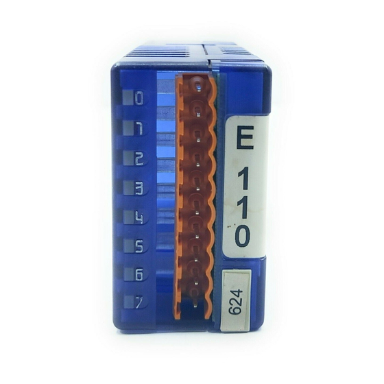
Page 80: Pcd3.E110/111, 8 Digital Inputs
(4 405 4957 0) or pluggable 10-pole screw terminal (4 405 4959 0), both for wires up to 2.5 mm² LED’s and connection terminals Terminal 0 LED 0...7 Terminal Description Label – Address Label Terminal 9 Hardware Manual for the PCD3 Series│Document 26/789; Version E 5│31.01.2005... - Page 81 Switch open : Input state "H" = LED on Ue 24 VDC Watchdog: This module can be used on all base addresses; there is no interaction with the watchdog for the CPUs. Hardware Manual for the PCD3 Series│Document 26/789; Version E 5│31.01.2005...
-
Page 82: Pcd3.E160, 16 Digital Inputs, Ribbon Cable Connector
16 I/Os with and without LED and relay interface; and terminal adapters with changeover contacts for signal conversion for digital output modules. For details, please refer to TI 26-326, “System cables”. 5-10 Hardware Manual for the PCD3 Series│Document 26/789; Version E 5│31.01.2005... - Page 83 240, the last input with address 255 cannot be used. Please refer to the “Watchdog” section for details on how to use the watchdog correctly together with PCD3 components. 5-11 Hardware Manual for the PCD3 Series│Document 26/789; Version E 5│31.01.2005...
-
Page 84: Pcd3.E165, 16 Digital Inputs, Screwless Terminals
Pluggable 24-pole cage clamp terminal (4 405 4958 0) for wires up to 1 mm² LED’s and connection terminals LED 0...15 Terminals Description Label – – – – Address Label 22 23 5-12 Hardware Manual for the PCD3 Series│Document 26/789; Version E 5│31.01.2005... - Page 85 240, the last input with address 255 cannot be used. Please refer to the ”Watchdog” section for details on how to use the watchdog correctly together with PCD3 components. 5-13 Hardware Manual for the PCD3 Series│Document 26/789; Version E 5│31.01.2005...
-
Page 86: Pcd3.E610, 8 Digital Inputs, Galvanically Isolated
10-pole screw terminal (4 405 4959 0), both for wires up to 2.5 mm² LED’s and connection terminals LED 0...7 Terminal 0 Terminal Description Label – Address Label Terminal 9 5-14 Hardware Manual for the PCD3 Series│Document 26/789; Version E 5│31.01.2005... - Page 87 Switch open : Input state "L" = LED on Ue 24 VDC Watchdog: This module can be used on all base addresses; there is no interaction with the watchdog for the CPUs. 5-15 Hardware Manual for the PCD3 Series│Document 26/789; Version E 5│31.01.2005...
-
Page 88: Pcd3.B100, 2 + 4 Digital Inputs /Outputs
If it is intended to read the status of a combined output, external voltage must be at least 17 VDC, as both the status and the LED are displayed via the input. 5-16 Hardware Manual for the PCD3 Series│Document 26/789; Version E 5│31.01.2005... - Page 89 However, if the input is shifted to 0 V with a changeover contact and the corresponding output is set in error, the MOSFET can be destroyed, as it is not short- circuit protected. For this reason, only positive-switching contacts should be used. 5-17 Hardware Manual for the PCD3 Series│Document 26/789; Version E 5│31.01.2005...
- Page 90 It is recommended that each module should be separately protected with a fast-blow 3.15A fuse. Watchdog: This module can be used on all base addresses; there is no interaction with the watchdog for the CPUs. 5-18 Hardware Manual for the PCD3 Series│Document 26/789; Version E 5│31.01.2005...
-
Page 91: Pcd3.A400, 8 Digital Outputs For 0.5 A Each
10-pole screw terminal (4 405 4959 0), both for wires up to 2.5 mm² LED’s and connection terminals LED 0...7 Terminal 0 Terminal Description Label 24VDC – Address Label Terminal 9 5-19 Hardware Manual for the PCD3 Series│Document 26/789; Version E 5│31.01.2005... - Page 92 4A. Watchdog: This module can be used on all base addresses, there is no interaction with the watchdog for the CPUs. 5-20 Hardware Manual for the PCD3 Series│Document 26/789; Version E 5│31.01.2005...
-
Page 93: Pcd3.A410, 8 Digital Outputs For 0.5 A Each, Galvanically Isolated
10-pole screw terminal (4 405 4959 0), both for wires up to 2.5 mm² LED’s and connection terminals LED 0...7 Terminal 0 Terminal Description Label 24VDC – Address Label Terminal 9 5-21 Hardware Manual for the PCD3 Series│Document 26/789; Version E 5│31.01.2005... - Page 94 4A. Watchdog: This module can be used on all base addresses; there is no interaction with the watchdog for the CPUs. 5-22 Hardware Manual for the PCD3 Series│Document 26/789; Version E 5│31.01.2005...
-
Page 95: Pcd3.A460, 16 Digital Outputs For 0.5A Each, Ribbon Cable Connector
Terminal: 34-pole, standard ribbon cable connector LED’s and connection terminals LED 0...15 Terminals – – – – Description Label – – – – Address Label 33 34 5-23 Hardware Manual for the PCD3 Series│Document 26/789; Version E 5│31.01.2005... - Page 96 240, the last output with address 255 mustn’t be wired and cannot be used. Please refer to the “Watchdog” section for details on to use the watchdog correctly together with PCD3 components. 5-24 Hardware Manual for the PCD3 Series│Document 26/789; Version E 5│31.01.2005...
-
Page 97: Pcd3.A465, 16 Digital Outputs, For 0.5A Each
Pluggable 24-pole cage clamp terminal (4 405 4958 0) for wires up to 1 mm² LED’s and connection terminals LED 0...15 Terminals Description Label – – – – Address Label 22 23 5-25 Hardware Manual for the PCD3 Series│Document 26/789; Version E 5│31.01.2005... - Page 98 240, the last output with address 255 must not be wired and cannot be used. Please refer to the “Watchdog” section for details on how to use the watchdog correctly together with PCD3 components. 5-26 Hardware Manual for the PCD3 Series│Document 26/789; Version E 5│31.01.2005...
-
Page 99: 5.2.10 Pcd3.A300, 6 Digital Outputs For 2A Each
10-pole screw terminal (4 405 4959 0), both for wires up to 2.5 mm² LED’s and connection terminals LED 0...7 Terminal 0 Terminal Description Label 24VDC – Address Label Terminal 9 5-27 Hardware Manual for the PCD3 Series│Document 26/789; Version E 5│31.01.2005... - Page 100 12,5 A. Watchdog: This module can be used on all base addresses; there is no interaction with the watchdog for the CPUs. 5-28 Hardware Manual for the PCD3 Series│Document 26/789; Version E 5│31.01.2005...
-
Page 101: Digital I/O Modules, 230 Vac
115 – 230 VAC (PCD3.A200...A220) 250VAC 80VAC 40VAC 0VAC I/O modules and I/O connectors must not be removed or plugged in while the PCD is connected to the power supply. 5-29 Hardware Manual for the PCD3 Series│Document 26/789; Version E 5│31.01.2005... -
Page 102: Pcd3.A200, 4 Relay Contacts, Type "No", With Contact Protection
10-pole screw terminal (4 405 4959 0), both for wires up to 2.5 mm² With external protective diode With reverse voltage protection These ratings are not UL-listed! 5-30 Hardware Manual for the PCD3 Series│Document 26/789; Version E 5│31.01.2005... - Page 103 PCD3.A220 module, without contact protection. Watchdog: This module can be used on all base addresses; there is no interaction with the watchdog for the CPUs. 5-31 Hardware Manual for the PCD3 Series│Document 26/789; Version E 5│31.01.2005...
-
Page 104: Pcd3.A210, 4 Relays With "Normally Closed" Contacts, With Contact Protection
Pluggable 10-pole cage clamp terminal (4 405 4957 0) or pluggable 10-pole screw terminal (4 405 4959 0), both for wires up to 2.5 mm² With external protective diode With reverse voltage protection These ratings are not UL-listed! 5-32 Hardware Manual for the PCD3 Series│Document 26/789; Version E 5│31.01.2005... - Page 105 24 VDC must be connected to the terminals “+” and “-”. Watchdog: This module can be used on all base addresses; there is no interaction with the watchdog for the CPUs. 5-33 Hardware Manual for the PCD3 Series│Document 26/789; Version E 5│31.01.2005...
-
Page 106: Pcd3.A220, 6 Relay Contacts, Type "No", W/O Contact Protection
10-pole screw terminal (4 405 4959 0), both for wires up to 2.5 mm² ) With external protective diode ) With reverse voltage protection ) These ratings are not UL-listed! 5-34 Hardware Manual for the PCD3 Series│Document 26/789; Version E 5│31.01.2005... - Page 107 24 VDC must be connected to terminals “+” and “–”. Watchdog: This module can be used on all base addresses; there is no interaction with the watchdog for the CPUs. 5-35 Hardware Manual for the PCD3 Series│Document 26/789; Version E 5│31.01.2005...
-
Page 108: Pcd3.A251, 6 Change-Over And 2 Make Relay Contacts 2A/48Vac
) With reverse voltage protection ) These ratings are not UL-listed! Higher voltages are not allowed for this module, because safety standards for clearance and creepage distances do not comply. 5-36 Hardware Manual for the PCD3 Series│Document 26/789; Version E 5│31.01.2005... - Page 109 24 VDC must be connected to terminals “+” and “–”. Watchdog: This module can be used on all base addresses; there is no interaction with the watchdog for the CPUs. 5-37 Hardware Manual for the PCD3 Series│Document 26/789; Version E 5│31.01.2005...
-
Page 110: Analogue I/O Modules
● Noise immunity: CE-mark according to EN 50 082-2 I/O modules and terminals must not be removed or plugged in while the PCD is connected to the power supply. 5-38 Hardware Manual for the PCD3 Series│Document 26/789; Version E 5│31.01.2005... -
Page 111: Pcd3.W2X0, Analogue Inputs, 8 Channels, 10 Bit Resolution
External current consumption: 0 mA Terminal: Pluggable 10-pole cage clamp terminal (4 405 4957 0) or pluggable 10-pole screw terminal (4 405 4959 0), both for wires up to 2.5 mm² 5-39 Hardware Manual for the PCD3 Series│Document 26/789; Version E 5│31.01.2005... - Page 112 – 10.0V – 20 mA Connection concept E 3 E 2 C O M For 0...10 V (W200) For 0...20 mA (W210) For Pt/Ni 1000 (W220) Earthing bar 5-40 Hardware Manual for the PCD3 Series│Document 26/789; Version E 5│31.01.2005...
- Page 113 Watchdog: This module cannot be used on the base address 240 because it would interact with the watchdog, which would cause malfunction. Please refer to the “Watchdog” section for details on how to use the watchdog correctly together with PCD3 components. 5-41 Hardware Manual for the PCD3 Series│Document 26/789; Version E 5│31.01.2005...
- Page 114 PCD3.W220. The digital value can be calculated as follows: 10 • R • 1023 (7500 + R) • 2.5 where 0 ≤ DV ≤ 1023 and R=the resistance to measure in Ω. 5-42 Hardware Manual for the PCD3 Series│Document 26/789; Version E 5│31.01.2005...
-
Page 115: Pcd3.W3X0, Analogue Inputs, 8 Channels, 12 Bit Resolution
Time constant of input filter: W300: typically 10.5 ms W310: typically 12.4 ms W340 V: typically 7.8 ms typically 24.2 ms typically 24.2 ms W350: typically 16.9 ms W360: typically 16.9 ms 5-43 Hardware Manual for the PCD3 Series│Document 26/789; Version E 5│31.01.2005... - Page 116 *) no negative input voltage should be applied on these modules. LED’s and Connection terminals Terminal – LED 0...7 Terminal 0 – Description Label – Address Label Terminal 9 – – 5-44 Hardware Manual for the PCD3 Series│Document 26/789; Version E 5│31.01.2005...
- Page 117 The following connection diagram shows a typical wiring layout for: ● voltage inputs with the PCD3.W300 and ...W340 modules or ● current inputs with the PCD3.W310 and ...W340 modules 5-45 Hardware Manual for the PCD3 Series│Document 26/789; Version E 5│31.01.2005...
- Page 118 The following connection diagram shows a typical layout for temperature sensors with the PCD3.W340, ...W350 and ...W360 modules. E 3 E 2 C O M Distributor *) Earthing bar *) potential free 5-46 Hardware Manual for the PCD3 Series│Document 26/789; Version E 5│31.01.2005...
- Page 119 Input- filter Gas- pression � 0...20 mA 24 VDC Tempera- ture � 4...20 mA* PCD3.W310/340 *4...20 mA via userprogram Two-wire transducers need a 24 VDC-supply in the measuring trunk. 5-47 Hardware Manual for the PCD3 Series│Document 26/789; Version E 5│31.01.2005...
- Page 120 Watchdog: These modules cannot be used on the base address 240 because it would interact with the watchdog, which would cause malfunction. Please refer to the “Watchdog” section for details on how to use the watchdog correctly together with PCD3 components. 5-48 Hardware Manual for the PCD3 Series│Document 26/789; Version E 5│31.01.2005...
- Page 121 PCD3.W3xx. The digital value can be calculated as follows: 10 • R • 4095 (7500 + R) • 2.5 where 0 ≤ DV ≤ 4095 and R=the resistance to measure in Ω. 5-49 Hardware Manual for the PCD3 Series│Document 26/789; Version E 5│31.01.2005...
-
Page 122: Pcd3.W3X5, Analogue Inputs, Galvanically Separated, 7 Channels, 12 Bit Resolution
Internal current consumption: 0 mA (from V+ bus) External current consumption: 0 mA Terminal: Pluggable 14-pole cage clamp terminal (4 405 4999 0) for wires up to 1.5 mm² 5-50 Hardware Manual for the PCD3 Series│Document 26/789; Version E 5│31.01.2005... - Page 123 PCD3.W305 and PCD3.W325 modules or current inputs with the PCD3.W315 ● If screened cables are used, screening should be continued to an external earthing bar 5-51 Hardware Manual for the PCD3 Series│Document 26/789; Version E 5│31.01.2005...
- Page 124 Saia-Burgess Controls Ltd. Hardware PCD3.W3x5 Earthing bar Block diagram Galvanic μController separated serial Interface DC / DC Converter I/O - Bus +5 V GND Reference- Voltage 2.5V PCD - Bus 5-52 Hardware Manual for the PCD3 Series│Document 26/789; Version E 5│31.01.2005...
- Page 125 RIO’s: the firmware reads the values according to the configuration (I/O Builder and Network configurator). Watchdog: These modules can be used on the base address 240, because it would not interact with the watchdog. 5-53 Hardware Manual for the PCD3 Series│Document 26/789; Version E 5│31.01.2005...
-
Page 126: Pcd3.W500, Analogue Inputs/Outputs, 2 + 2 Channels, 12 Bit Resolution
Since the current consumption of this module is considerable, when using a number of them in the same system, the total load for all modules must be taken into consideration. 5-54 Hardware Manual for the PCD3 Series│Document 26/789; Version E 5│31.01.2005... - Page 127 Digital values Output signals Classic Simatic unipolar bipolar 4095 4095 27648 +10.0V +10.0V 3071 3071 20736 +7.5V + 5.0V 2047 2047 13824 +5.0V 1023 1023 6912 +2.5V -5.0V -10.0V 5-55 Hardware Manual for the PCD3 Series│Document 26/789; Version E 5│31.01.2005...
- Page 128 The module is also working without the additional Plug-on module. Changing the jumpers Throughout the circuit board there are components which are sensitive to electrostatic discharges. Explanation will be found in the Appendix, “Icons” section. 5-56 Hardware Manual for the PCD3 Series│Document 26/789; Version E 5│31.01.2005...
- Page 129 Watchdog: This module cannot be used on the base address 240 because it would interact with the watchdog, which would cause malfunction. Please refer to the “Watchdog” section for details on how to use the watchdog correctly together with PCD3 components. 5-57 Hardware Manual for the PCD3 Series│Document 26/789; Version E 5│31.01.2005...
- Page 130 (type PCD3.W410 only for current outputs) Terminal: Pluggable 10-pole cage clamp terminal (4 405 4957 0) or pluggable 10-pole screw terminal (4 405 4959 0), both for wires up to 2.5 mm² 5-58 Hardware Manual for the PCD3 Series│Document 26/789; Version E 5│31.01.2005...
- Page 131 4 to 20 mA Digital values Classic Simatic 27648 10.0V 20 mA 20 mA 13824 5.0V*) 10 mA*) 12 mA*) 4 mA *) The exact values are 1/255 higher 5-59 Hardware Manual for the PCD3 Series│Document 26/789; Version E 5│31.01.2005...
- Page 132 (selectable with jumpers on type PCD3.W410) An external 24 VDC supply voltage is required for current outputs. + 24 VDC VOLTAGE CONTROLLED CURRENT SOURCE 4 (A2) R = 0.. 500 5-60 Hardware Manual for the PCD3 Series│Document 26/789; Version E 5│31.01.2005...
- Page 133 Watchdog: These modules cannot be used on the base address 240 because it would interact with the watchdog, which would cause malfunction. Please refer to the “Watchdog” section for details on how to use the watchdog correctly together with PCD3 components. 5-61 Hardware Manual for the PCD3 Series│Document 26/789; Version E 5│31.01.2005...
- Page 134 (0 mA, 20 mA), current outputs have been laid out according to the following characteristic line: 20.1 mA 20 mA 19.94 mA Tolerance +/- 0.5% typ. Tolerance +/- 0.8% max. 0.06 mA 0 mA 4075 4095 5-62 Hardware Manual for the PCD3 Series│Document 26/789; Version E 5│31.01.2005...
- Page 135 24VDC – Digital/analogue values Digital values Output signals Classic Simatic 4095 4095 27648 +20.1 mA 4075 4075 27513 +20 mA 2048 2048 13824 +10 mA 0 mA 0 mA 5-63 Hardware Manual for the PCD3 Series│Document 26/789; Version E 5│31.01.2005...
- Page 136 Current output: 0...20 mA Current outputs have been laid out for unipolar mode. Bipolar mode is possible, but for the negative half of this operation the output is 0 mA. 5-64 Hardware Manual for the PCD3 Series│Document 26/789; Version E 5│31.01.2005...
- Page 137 An external 24 VDC supply is required for current outputs Block diagram /IOOUIT IODIN Data /IOWRITE IODOUT I/MS0 IOA0 IOA1 IOA2 IOA3 Filter +15V Unipolar/ DC/DC -15V Ref. bipolar Voltage switch 2.500V 5-65 Hardware Manual for the PCD3 Series│Document 26/789; Version E 5│31.01.2005...
- Page 138 Watchdog: These modules cannot be used on the base address 240 because it would interact with the watchdog, which would cause malfunction. Please refer to the “Watchdog” section for details about how to use the watchdog correctly together with PCD3 components. 5-66 Hardware Manual for the PCD3 Series│Document 26/789; Version E 5│31.01.2005...
-
Page 139: Pcd3.W6X5, Analogue Outputs, Galvanically Isolated, 6 Resp. 4 Channels
RL=500 Ω → Ue = 20...30 V RL=0 Ω → Ue = 10...20 V Terminal: Pluggable 14-pole cage clamp terminal (4 405 4999 0) for wires up to 1.5 mm² 5-67 Hardware Manual for the PCD3 Series│Document 26/789; Version E 5│31.01.2005... - Page 140 This range corresponds with 10 bit (1024 steps) as before. The result is the following LSB resolution: W605: 1 LSB = 10.38 µV W615: 1 LSB = 21.7 µA W625: 1 LSB = 20.75 µV 5-68 Hardware Manual for the PCD3 Series│Document 26/789; Version E 5│31.01.2005...
- Page 141 R 3 k Connection for 0...20 mA (PCD3.W615): + 24 VDC VOLTAGE CONTROLLED CURRENT SOURCE 4 (A2) Ω R = 0...500 An external 24 VDC supply is required for current outputs 5-69 Hardware Manual for the PCD3 Series│Document 26/789; Version E 5│31.01.2005...
- Page 142 RIO’s: the firmware reads the values according to the configuration (I/O Builder and Network configurator). Watchdog: These modules can be used on the base address 240, because it would not interact with the watchdog. 5-70 Hardware Manual for the PCD3 Series│Document 26/789; Version E 5│31.01.2005...
-
Page 143: Weighingsystems And Thermocouple Module
4/6 wire weighing cells ¹), ²) PCD3.W745 Thermocouple module for J, see Manual K...Thermo-elements 26/796 Thermocouple module ¹) in preparation ²) These I/O modules cannot currently be used with the PCD3.RIO on demand 5-71 Hardware Manual for the PCD3 Series│Document 26/789; Version E 5│31.01.2005... - Page 144 Saia-Burgess Controls Ltd. Hardware PCD3.W7xx 5-72 Hardware Manual for the PCD3 Series│Document 26/789; Version E 5│31.01.2005...
-
Page 145: Counting And Motion Control I/O Modules
The PG5 programming tool also allows the automatic integration of software libraries, initialization for programming and use of the new CSF instructions, which guarantee very fast processing of user cycles in the Saia ® PCD. 5-73 Hardware Manual for the PCD3 Series│Document 26/789; Version E 5│31.01.2005... -
Page 146: Pcd3.H100, Simple Counting Module
CE mark according to EN 50 081-1 and EN 50082-2 Programming: Based on PCD user program (PG5) and pre- programmed functional blocks (FB). For the use with RIOs other FBs exist. 5-74 Hardware Manual for the PCD3 Series│Document 26/789; Version E 5│31.01.2005... - Page 147 0 “CCO” output “CCO” Changing the jumpers Throughout the circuit board there are components which are sensitive to electrostatic discharges. Explanation will be found in the Appendix, “Icons” section. 5-75 Hardware Manual for the PCD3 Series│Document 26/789; Version E 5│31.01.2005...
- Page 148 To enable signals at input A can be counted, input B must be connected to 24V (AND gate). Filter Modes x1, x2 Up/down counting mode for two-phase incremental shaft encoder at inputs A and B 5-76 Hardware Manual for the PCD3 Series│Document 26/789; Version E 5│31.01.2005...
- Page 149 Resetting the counter flag results in a simultaneous reset of the CCO output. 50'000 Counter Flag Reset Enable The “Reset Enable” should be activated before the counter reaches zero. 5-77 Hardware Manual for the PCD3 Series│Document 26/789; Version E 5│31.01.2005...
- Page 150 Watchdog: This module cannot be used on the base address 240 because it would interact with the watchdog, which would cause malfunction. Please refer to the “Watchdog” section for details on how to use the watchdog correctly together with PCD3 components. 5-78 Hardware Manual for the PCD3 Series│Document 26/789; Version E 5│31.01.2005...
-
Page 151: Pcd3.H110, Universal Counting And Measuring Module
2 A, residual ripple max. 10% Operational conditions Ambient temperature: operation 0...+55°C without forced ventilation storage -20...+85°C Interference immunity: CE mark according to EN 50 081-1 and EN 50082-2 5-79 Hardware Manual for the PCD3 Series│Document 26/789; Version E 5│31.01.2005... - Page 152 Watchdog: This module cannot be used on the base address 240 because it would interact with the watchdog, which would cause malfunction. Please refer to the “Watchdog” section for details on how to use the watchdog correctly together with PCD3 components. 5-80 Hardware Manual for the PCD3 Series│Document 26/789; Version E 5│31.01.2005...
-
Page 153: Pcd3.H150, Ssi Interface For Absolute Encoder
Output delay: typically. 50 μs, max. 100 μs, ohmic load Power supply Internal current consumption: 25 mA (from +5 V bus) Internal current consumption: 0 mA (from V+ bus) 5-81 Hardware Manual for the PCD3 Series│Document 26/789; Version E 5│31.01.2005... - Page 154 2.5 mm² LED’s and connection terminals LED 0...7 Terminal 0 Terminal LEDs /CLK Clock Data Description Label – Address Label In/Output Terminal 9 /CLK 5-82 Hardware Manual for the PCD3 Series│Document 26/789; Version E 5│31.01.2005...
- Page 155 Watchdog: This module cannot be used on the base address 240 because it would interact with the watchdog, which would cause malfunction. Please refer to the “Watchdog” section for details on how to use the watchdog correctly together with PCD3 components. 5-83 Hardware Manual for the PCD3 Series│Document 26/789; Version E 5│31.01.2005...
-
Page 156: Pcd3.H210, Motion Control Module For Stepper Motors
Switching capacity: 0.5 A each in the range 5...32 VDC, residual ripple max. 10% Short circuit protection: Electrical isolation: Voltage drop: max. 0.3 V at 0.5 A 5-84 Hardware Manual for the PCD3 Series│Document 26/789; Version E 5│31.01.2005... - Page 157 LED E2:*) Voltage at input 2: (REF) LED A2: Voltage at output 2 LED E3:*) Voltage at input 3: (LS2) LED A3: Voltage at output 3 *) status inverted when used as limit switch 5-85 Hardware Manual for the PCD3 Series│Document 26/789; Version E 5│31.01.2005...
- Page 158 Watchdog: This module cannot be used on the base address 240 because it would interact with the watchdog, which would cause malfunction. Please refer to the “Watchdog” section for details on how to use the watchdog correctly together with PCD3 components. 5-86 Hardware Manual for the PCD3 Series│Document 26/789; Version E 5│31.01.2005...
-
Page 159: Pcd3.H31X, Motion Control Modules For Servo Drives
Analogue controller output resolution 12 bit (with sign bit) Short circuit protection Electrical isolation Output voltage *) ± 10 V, accuracy of adjustment ± 5 mV Minimum load impedance 3 kΩ 5-87 Hardware Manual for the PCD3 Series│Document 26/789; Version E 5│31.01.2005... - Page 160 Terminal: Pluggable 10-pole cage clamp terminal (4 405 4957 0) or pluggable 10-pole screw terminal (4 405 4959 0) , both for wires up to 2.5 mm² 5-88 Hardware Manual for the PCD3 Series│Document 26/789; Version E 5│31.01.2005...
- Page 161 = external supply terminals = output for encoder’s 5V supply (300 mA max.) = analogue controller output A, B, IN = non inverted encoder signals /A, /B, /IN = inverted encoder signals 5-89 Hardware Manual for the PCD3 Series│Document 26/789; Version E 5│31.01.2005...
- Page 162 Watchdog: This module cannot be used on the base address 240 because it would interact with the watchdog, which would cause malfunction. Please refer to the “Watchdog” section for details on how to use the watchdog correctly together with PCD3 components. 5-90 Hardware Manual for the PCD3 Series│Document 26/789; Version E 5│31.01.2005...
-
Page 163: Configuration
Configuration CPUs Connecting the PCD to the configuration with PG5: Start up PG5 1.3 Create new project: ● Click on “New…” ● The “New Project” dialogue is displayed Hardware Manual for the PCD3 Series│Document 26/789; Version E 5│31.01.2005... - Page 164 CPU. The “New CPU” command can be used to add a CPU. ● Enter project name, e.g. “First Project” ● Check “Create CPU” option ● Click “OK” Hardware Manual for the PCD3 Series│Document 26/789; Version E 5│31.01.2005...
- Page 165 ● Tick PGU option ● Click “OK” Now connect the PCD to the PC via the USB cable. Ensure that the PCD is connected to the 24 VDC supply. Hardware Manual for the PCD3 Series│Document 26/789; Version E 5│31.01.2005...
- Page 166 Saia-Burgess Controls Ltd. Configuration CPUs Go to “Hardware Settings”: ● Click on “Upload…”, to copy the settings from the CPU. ● Click on “Upload…” ● Click “OK” Hardware Manual for the PCD3 Series│Document 26/789; Version E 5│31.01.2005...
- Page 167 Configuration CPUs The connection of the PCD to the configuration with PG5 via the PC is complete. The hardware settings can now be changed and programming the application can begin. Hardware Manual for the PCD3 Series│Document 26/789; Version E 5│31.01.2005...
-
Page 168: Rios
“Network Configurator” window is displayed, with the relevant file name. Here, a PCD3 has already been selected as “Master”. By pressing or the “Enter” key, move the PCD into the right half of the window. Hardware Manual for the PCD3 Series│Document 26/789; Version E 5│31.01.2005... - Page 169 The “Associated CPU File” field is used to enter the desired CPU name. By pressing the “Existing CPU...” button, a specific CPU can be selected from the list. This tells the Configurator which CPU should be mapped to the icon. Hardware Manual for the PCD3 Series│Document 26/789; Version E 5│31.01.2005...
- Page 170 These are the entries for this CPU; click “OK” to finish. Confirmation: Definition of PCD3.RIO One PCD3.RIO has already been positioned in this window. Double-click on the “PCD3.RIO DP Slave” icon. Hardware Manual for the PCD3 Series│Document 26/789; Version E 5│31.01.2005...
- Page 171 RIO with the DIP switch. “Parameters” tab Option to swap the “Low” byte with the “High” byte for a 16-channel I/O module. Hardware Manual for the PCD3 Series│Document 26/789; Version E 5│31.01.2005...
- Page 172 “Installed Module Configuration”. Select next module. As the exchange of data between Master (PCD3.CPU) and Slave (PCD3.RIO) is controlled by flags and registers, these must be mapped to the I/O modules. 6-10 Hardware Manual for the PCD3 Series│Document 26/789; Version E 5│31.01.2005...
- Page 173 More convenient: first define the symbol name for “Media Number 0”, and then press the “Set Defaults” button; the elements will be automatically numbered from 0 to 7. Further RIO I/O modules can be configured in the same way. 6-11 Hardware Manual for the PCD3 Series│Document 26/789; Version E 5│31.01.2005...
- Page 174 Saia-Burgess Controls Ltd. Configuration RIOs Some I/O modules can be parameterized. An example, with parameters for the PCD3.W340: The result is a list of all the modules required in this example. 6-12 Hardware Manual for the PCD3 Series│Document 26/789; Version E 5│31.01.2005...
- Page 175 Saia-Burgess Controls Ltd. Configuration RIOs “Device” tab Information on current RIO nodes “Bus” tab Information on possible transmission rates Complete the configuration of the RIO node by pressing “OK”. 6-13 Hardware Manual for the PCD3 Series│Document 26/789; Version E 5│31.01.2005...
- Page 176 Acknowledge the message below with “Yes”. If an error message is returned during the compilation, all details entered for this example should be checked from the beginning. If everything is OK: 6-14 Hardware Manual for the PCD3 Series│Document 26/789; Version E 5│31.01.2005...
- Page 177 Saia-Burgess Controls Ltd. Configuration RIOs The “Consistency check” function can be used to check for possible conflicts with other elements of the user program. 6-15 Hardware Manual for the PCD3 Series│Document 26/789; Version E 5│31.01.2005...
-
Page 178: Web Server
To ensure that the installation has been executed correctly, launch Explorer, go to the “Tools” menu and select “Internet Options”. The window below will appear; select the ”Advanced” tab and check that the JavaSun option is ticked: 6-16 Hardware Manual for the PCD3 Series│Document 26/789; Version E 5│31.01.2005... -
Page 179: Device-Specific Web
field within the web browser: http://localhost/ The screen will display a standard web page, similar to the page shown overleaf. Now click on the link pointing to the PCD3.T76x. 6-17 Hardware Manual for the PCD3 Series│Document 26/789; Version E 5│31.01.2005... - Page 180 Saia-Burgess Controls Ltd. Configuration RIOs If no connection to the PD3.T76x has been defined, this can be rectified now, using the Setup page: http://localhost/setup 6-18 Hardware Manual for the PCD3 Series│Document 26/789; Version E 5│31.01.2005...
- Page 181 Saia-Burgess Controls Ltd. Configuration RIOs Add new stations with the following parameters: 6-19 Hardware Manual for the PCD3 Series│Document 26/789; Version E 5│31.01.2005...
- Page 182 Directory tree with all possible modules that can be plugged into the PCD3.T76x Control field with status LEDs for the PCD3.T76x. List of possible and already configured module positions on the PCD3.T76x (0-15) 6-20 Hardware Manual for the PCD3 Series│Document 26/789; Version E 5│31.01.2005...
- Page 183 This function is not available in Monitoring mode. The two configurations, in the PCD3.T76x itself and in the device-specific web pages for the PCD3.T76x, must be identical. This function saves the configuration from the PCD3.T76x to its EEPROM. 6-21 Hardware Manual for the PCD3 Series│Document 26/789; Version E 5│31.01.2005...
- Page 184 PCD3.T76x. If the two configurations are not the same, some functions, such as “Start Monitoring” and “Save to EEPROM”, will not be available. In this case, the buttons for these functions will be blocked, as shown on the next page. 6-22 Hardware Manual for the PCD3 Series│Document 26/789; Version E 5│31.01.2005...
- Page 185 Typing “firmware” into this field and pressing Enter takes the PCD3.T76x into “Firmware update mode”. To return to Operating mode, it is necessary to switch the power off and on again (POWER OFF and ON). 6-23 Hardware Manual for the PCD3 Series│Document 26/789; Version E 5│31.01.2005...
- Page 186 Two ways of reconnecting the PCD3.T76x to the network: ● “Reconnect Master” button ● Switching the supply to the PCD3.T76x off and on again. On POWER ON, the PCD3.T76x is reconnected to the Master (default setting). 6-24 Hardware Manual for the PCD3 Series│Document 26/789; Version E 5│31.01.2005...
- Page 187 Pt1000, Ni1000, Pt100, Ni100, S7 format, etc. To enter parameters, double-click on the module, or select the module and press “Enter” on the keyboard. This is the screen to parameterize a PCD3.W500 module. 6-25 Hardware Manual for the PCD3 Series│Document 26/789; Version E 5│31.01.2005...
- Page 188 Examples of digital and analogue output modules: To switch off monitoring, press STOP or click on the cross in the top right corner of the window. 6-26 Hardware Manual for the PCD3 Series│Document 26/789; Version E 5│31.01.2005...
- Page 189 The locked value has the highest priority. The locks are stored in the PCD3. T76x RAM and/or EEPROM. If they are in EEPROM, they will be activated after every POWER OFF and ON. 6-27 Hardware Manual for the PCD3 Series│Document 26/789; Version E 5│31.01.2005...
- Page 190 Monitoring window: Output 1 locked “ON”, Output 4 locked “OFF”, Both have a “lock” icon to the left of the LED. For analogue I/Os, the same icon is used. 6-28 Hardware Manual for the PCD3 Series│Document 26/789; Version E 5│31.01.2005...
-
Page 191: Application-Specific Web
“lock” icon disappears from the Monitoring window. 6.2.4 Application-specific web pages The PCD3.T76x web server also allows application-specific web pages to be stored. The description of the procedure for this is in preparation. 6-29 Hardware Manual for the PCD3 Series│Document 26/789; Version E 5│31.01.2005... -
Page 192: Maintenance
flat or shows an interrupt the battery is missing We recommend changing the batteries with the PCD attached to the power supply, to avoid any loss of data. Hardware Manual for the PCD3 Series│Document 26/789; Version E 5│31.01.2005... -
Page 193: Other Pcd3 Components (In Preparation)
Saia-Burgess Controls Ltd. Maintenance Other PCD3 components Other PCD3 components (in preparation) Hardware Manual for the PCD3 Series│Document 26/789; Version E 5│31.01.2005... -
Page 194: Troubleshooting
Saia-Burgess Controls Ltd. Troubleshooting CPUs Troubleshooting CPUs (in preparation) Hardware Manual for the PCD3 Series│Document 26/789; Version E 5│31.01.2005... -
Page 195: Rios
Saia-Burgess Controls Ltd. Troubleshooting RIOs RIOs For troubleshooting, please refer to manual 26/765 “PROFIBUS-DP”. Diagnostics The RIO itself provides a whole range of diagnostic facilities. These are described in section 3.19.6. Hardware Manual for the PCD3 Series│Document 26/789; Version E 5│31.01.2005... -
Page 196: Appendix 9.1 Icons
This sign accompanies instructions that must always be followed. Explanations beside this sign are valid only for the SAIA-Burgess PCD Classic series. Explanations beside this sign are valid only for the SAIA-Burgess PCD xx7 series. Hardware Manual for the PCD3 Series│Document 26/789; Version E 5│31.01.2005... -
Page 197: Definitions Of Serial Interfaces
-7 V message signal 1 (on) +3 V to +15 V +7 V The idle state of the data signals = “mark” of the control and message signals = “off” Hardware Manual for the PCD3 Series│Document 26/789; Version E 5│31.01.2005... - Page 198 To guarantee error-free operation of an RS 485 network, the network should be terminated at both ends. Cable and line termination resistors should be selected in accordance with manual 26/740 “Installation components for RS 485 networks”. Hardware Manual for the PCD3 Series│Document 26/789; Version E 5│31.01.2005...
-
Page 199: Tty/Current Loop
The idle state of the data signals = “mark” By wiring to the cable connector, the user selects either an “active” or “passive” circuit. The max. transmission rate for TTY/current loops at 20 mA is 9600 bps. Hardware Manual for the PCD3 Series│Document 26/789; Version E 5│31.01.2005... -
Page 200: Order Details
Input delay typically 8 ms (pulsed voltage possible, connection via 24-pole spring terminal block) 65 g with 8 inputs 24 VDC, electrically isolated PCD3.E610 Input delay typically 10 ms (pulsed voltage possible) 65 g Hardware Manual for the PCD3 Series│Document 26/789; Version E 5│31.01.2005... - Page 201 4 channels selectable by jumper, 0...10 V und –10...+10 V (≥ 3 kΩ) or 0...20 mA (≤ 500 Ω) 45 g Analogue input and output modules, 12 bit resolution PCD3.W500 2 input and 2 output channels for voltage signals 80 g Hardware Manual for the PCD3 Series│Document 26/789; Version E 5│31.01.2005...
- Page 202 Set of 10: Pluggable I/O spring terminal block, 14-pole (Type E) 135 g 4 329 4819 0 Label plates (10) 4 310 8686 0 Pre-printed tape PCD3.K225 Connecting cable 2.5 m PCD3 web server↔PC Hardware Manual for the PCD3 Series│Document 26/789; Version E 5│31.01.2005...
-
Page 203: Address Of Saia-Burgess Controls Ag
Saia-Burgess Controls AG Bahnhofstrasse 18 CH-3280 Murten / Switzerland Tel: +41 26 / 672 71 11 Fax: +41 26 / 672 74 99 E-mail: pcd@saia-burgess.com Home page: www.saia-burgess.com Support: www.sbc-support.ch Hardware Manual for the PCD3 Series│Document 26/789; Version E 5│31.01.2005...
Need help?
Do you have a question about the PCD3 Series and is the answer not in the manual?
Questions and answers