
Related Manuals for Centroid DP-4

Summary of Contents for Centroid DP-4
- Page 1 DP-4 Touch Probe Operator's Manual U.S Patent #6553682 Rev 2019-05-28 Copyright © 2003-2020 Centroid Corporation Howard, PA 16841...
- Page 2 5. Install a tool holder in the spindle then install the DP-4 and then the stylus. See Stylus installation procedures on page 3 and perform run-out adjustment as shown on page 3 and 4.
-
Page 3: Table Of Contents
Page 13 Cutting a Copy of Digitized Part, Tips Page 14 Appendix A – Centroid Control System CNC12 application data Appendix B – Centroid Control System CNC11 application data Appendix C – Centroid Control System CNC10 application data Appendix D – Non-Centroid Control System application data... -
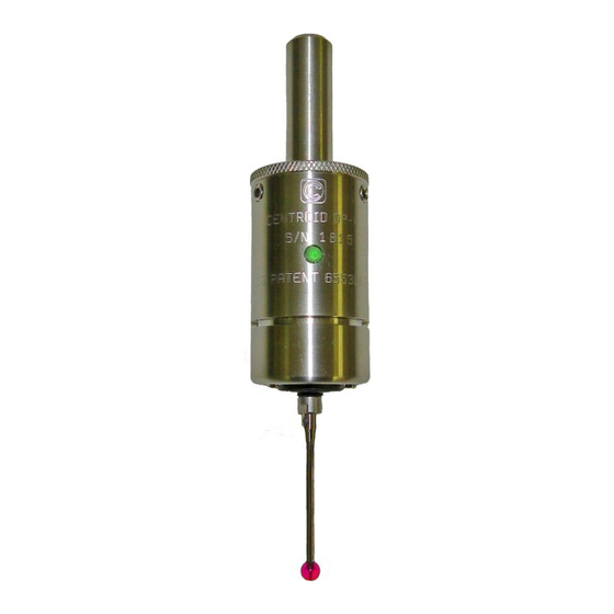
Page 4: General Description
DP-4 front and rear views shown with optional stylus attached. GENERAL DESCRIPTION: The DP-4 is a “touch probe” intended for probing to find part zero’s, reference positions, locate bores, bases, corners etc., and digitizing which allows for the copying of surfaces and shaped objects. The user should first become familiar with the various parts and features of the probe as shown above to facilitate assembly, installation and calibration. -
Page 5: Dp-4 Specifications
DP-4 SPECIFICATIONS: Probing directions X+/-, Y+/-, Z- Unidirectional repeatability (2 sigma) 0.00004” (1 micron) Probe deflection force (X,Y) 3 ounce minimum with 40mm stylus Pre-travel variation X-Y plane 0.001” with 40 mm stylus Probe deflection force (Z) 9 ounce minimum Probe body diameter and length D= 1.25”... -
Page 6: Stylus Installation And Alignment Procedures
Install the complete assembly into the milling machine spindle without the retractile cord. STEP 3: Install the 2.5 or 5mm stylus in your DP-4 probe. Thread the stylus into the probe stylus mount boss until finger tight. Insert the stylus tightening pin, from your tool kit, into the hole located at the base of the stylus stem and place the 3/16"... -
Page 7: Run-Out Adjustment "Dialing-In
RUN-OUT ADJUSTMENT: STEP 4: Position the dial indicator, as shown in the photo below, with the finger of the dial indicator on the front and center of the stylus ball. Insert the 3/32” hex wrench in the run-out adjustment set screw directly above the finger of the dial indicator. -
Page 8: Angular Alignment Adjustment
Be sure all set screws are equally tight when finished. OUTPUT SWITCH LOGIC SELECTION: The DP-4 output is a solid state switch that can be configured for normally open or closed logic. This choice can be specified when ordering (recommended) or can be changed in the field. The standard configuration for the stock DP-4 is normally open. -
Page 9: Initial Control/Probe Setup Procedure
STEP 2: Plug the 6' retractile cord into the DP-4 probe and into the digitizing port on the control. The cord ends are keyed to prevent incorrect connection. At the probe end line-up the red dot with the red painted slot on the probe connector, push the plug in until it clicks. - Page 10 Go to the Tool Library and enter the calibrated diameter for the probe stylus in the tool# you assigned to the probe in Parameter 12. The Probe Stylus Calibration is now complete. Your DP-4 probe is ready for probing and digitizing!
-
Page 11: Performance Characteristics
PRE-TRAVEL VARIATION, RADIAL DIGITIZING PRECISION BORE Typical pre-travel variation for DP-4 probe showing variation over 720 degrees of radial digitizing routine of precision bore. Inside circle represents the minimum value and the outside circle the maximum. Data was collected probing at 1 inch per minute with a 43mm long stylus. -
Page 12: Maintenance And Care
This will re-distribute lube and spring pressure. If the probe indicator LED contiues to stay red the probe may be damaged and must be returned for evaluation and repair. The DP-4 has no internal user serviceable parts or adjustments and should only be serviced by Centroid. -
Page 13: Kit Contents
M3 thread 40mmlength p/n: 3360 Precision ring gauge p/n: 3193 Size and type may vary DP-4 Probe complete kit with protective case and accessories. Inset shows outside of case. Kit contains the accessories shown above plus the retractile coil cord p/n: 10394. -
Page 14: Common Cables
COMMON CABLES: The photo below shows the DP-4 connected to the primary cable assemblies common to all new Centroid control installations. Note the bulkhead connector to provide physical support for the coil cord. No additional adapters are needed for new Centroid (TM) systems. See the appropriate appendix in this manual for additional required adapters, connection diagrams and parameter settings for your installation. -
Page 15: Connection Diagram Universal
CONNECTION DIAGRAM UNIVERSAL This diagram provides the basic function of each pin in the DP-4 electrical connector and is the starting point for interfacing the DP-4 to non-Centroid control systems or trouble-shooting existing systems. The COIL CORD pinout and internal wire colors are also presented to facilitate installing custom connectors for non-Centroid systems. -
Page 16: Grid Digitizing Tips
Remember, the Centroid control can digitize unattended, 24 hours a day, 7 days a week, if you really need the detail and finish, (just remember to fill the automatic oiler tank!). -
Page 17: Cutting A Copy Of Digitized Part, Tips
0.125”. You can also import your digitized data into an online CAM program on your Centroid control or export it to an offline CAM system. The “Dig to CAD” menu in the Digitizing screen is used to convert... - Page 18 APPENDIX A CENTROID CNC12 PROBE CONFIGURATION (see control manual for additional information) CNC12 control system parameter recommended basic settings SAE inch (mm) Parameter Setting Description 50769 PLC input, probe signal Tool library number for probe 0.020 (0.508) Clearance amount nominal...
- Page 19 APPENDIX B CENTROID CNC11 PROBE CONFIGURATION (see control manual for additional information) CNC11 control system parameter recommended basic settings SAE inch (mm) Parameter Setting Description 50769 PLC probe input number Tool library number for probe 0.020 (0.508) Clearance amount nominal...
- Page 20 APPENDIX C CENTROID CNC10 PROBE CONFIGURATION (see control manual for additional information) CNC10 control system parameter recommended basic settings SAE inch (mm) Parameter Setting Description Modal Tool and Height Offset Control Enables decel on probe contact PLC probe input number Tool library number for probe 0.020 (0.508)
- Page 21 Determine if signal must be normally open or normally closed. See OUTPUT SWITCH LOGIC SELECTION in this manual. The DP-4 output and power connection have a common connection. This may limit some direct wire options, specifically those that require a current source signal. The circuit shown below can be used to convert the probe tripped signal from current sink to current source if necessary.
Need help?
Do you have a question about the DP-4 and is the answer not in the manual?
Questions and answers