Table of Contents
Advertisement
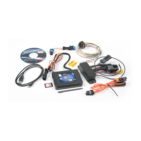
LAUNCHER PROGRESSIVE NITROUS CONTROLLER
P/N's 15975NOS, 15977NOS and Upgrade Kits
INSTALLATION AND OPERATION INSTRUCTIONS
199R10466
CONGRATULATIONS on purchasing your NOS Launcher Progressive controller! Your system is composed of the highest quality
components available. It should provide many miles of trouble-free performance when used correctly. If you have any questions regarding
the performance of your system, call NOS Technical Service at 1-866-464-6553.
NOTICE: Installation of Nitrous Oxide Systems Inc. products signifies that you have read this document and have agreed to the
terms stated within.
It is the purchaser's responsibility to follow all installation instruction guidelines and safety procedures supplied with the product as it is
received by the purchaser to determine the compatibility of the product with the vehicle or the device the purchaser intends to install the
product on.
Nitrous Oxide Systems Inc. assumes no responsibility for damages occurring from accident, misuse, abuse, improper installation, improper
operation, lack of reasonable care, or all previously stated reasons resulting from incompatibility with other manufacturers' products.
Nitrous Oxide Systems Inc. assumes no responsibility or liability for damages incurred by the use of products manufactured or sold by
Nitrous Oxide Systems Inc. on vehicles used for competition or racing.
Nitrous Oxide Systems Inc. neither recommends nor condones the use of products manufactured or sold by Nitrous Oxide Systems Inc. on
vehicles, which may be driven on public roads or highways, and assumes no responsibility for damages incurred by such use.
NOS nitrous oxide is legal for use in most states when used in accordance with state and local traffic laws. NOS does not recommend or
condone the use of its products in illegal racing activities.
NOS has not pursued California Air Research Board (CARB) exemptions for these kits, hence, they are not legal for use on pollution-
controlled vehicles in California. A correctly installed NOS nitrous system should not alter the emission control performance of your vehicle
under standard EPA test cycle conditions.
HAZARDS DEFINED
This manual presents step-by-step instructions that describe the process of installing your NOS Launcher Progressive Nitrous Controller.
These procedures provide a framework for installation and operation of this kit. Within the instructions, you are advised of potential
hazards, pitfalls, and problems to avoid. The following examples explain the various hazard levels:
WARNING! Failure to comply with instructions may result in injury or death.
CAUTION! Failure to comply with instructions may result in damage to equipment.
NOTE: This information is important, needs to be emphasized, and is set apart from the rest of the text.
HINT: These special instructions provide a handy work tip.
Advertisement
Table of Contents

Subscribe to Our Youtube Channel
Related Manuals for Nos Launcher 15975NOS

Summary of Contents for Nos Launcher 15975NOS
- Page 1 NOS nitrous oxide is legal for use in most states when used in accordance with state and local traffic laws. NOS does not recommend or condone the use of its products in illegal racing activities.
- Page 2 Increasing the safety relief valve pressure settings may create an explosive bottle hazard. Please note that the NOS bottle label has changed to a two-part assembly. The first label is already located on the bottle. Upon filling your bottle with nitrous oxide, apply the (second) material information label in the area indicated in the picture to the right.
-
Page 3: Table Of Contents
TABLE OF CONTENTS Chapter 1 Product Overview ............................4 Chapter 2 Hardware Installation ..........................4 2.1 Master Controller Installation and Wiring ....................... 4 2.2 Hand-Held Controller and Touch Screen LCD Wiring Installation ............... 5 2.3 Slave Controller Installation ..........................6 2.4 Wide Band Oxygen Sensor Controller Installation .................. -
Page 4: Chapter 1 Product Overview
Chapter 1 Product Overview The NOS Launcher Progressive Nitrous Controller is a fully featured progressive nitrous controller offering control of up to 4 individual stages . These features make this the most advanced nitrous control system on the market. A master controller controls two stages and an additional add-on slave controller can control up to two more stages. -
Page 5: Hand-Held Controller And Touch Screen Lcd Wiring Installation
Before mounting the master or slave controller, write down the Master ID/serial number for them. This number is located on the back of the unit. It is the upper right-hand number and is indicated by ID#. Find a suitable mounting place for the main controller. Mount it securely. -
Page 6: Slave Controller Installation
Connect the orange NOSbus wires to the master controller. See section 2.5. The units should now be recognized and ready for use. 2.3 Slave Controller Installation If the optional slave controller is being used (PN 15978NOS), install it now. The slave controller offers an additional 2 stages of nitrous capability. -
Page 7: Nosbus Wiring
NOTE: Make sure the brown wire loop is cut if using a Bosch sensor. If the wire loop is not appropriate for the sensor, damage can result. This kit comes with a 5 foot harness to power the controller. The wire colors are black and red. Connect the black wire to a clean, sound chassis ground. -
Page 8: Chapter 3 System Communications
4.2 Software Overview There are two kinds of files that this system uses. They are Nitrous Configuration Files which have a .nos filename extension and Nitrous Datalog files which have a .noslog or .log filename extension. The Nitrous Configuation File are the actual “tuneup” files that dictate the operation of the system. -
Page 9: General Settings
IMPORTANT NOTE: In order for proper communication, the file that is in the controller must have the proper “Master Serial Number” entered. See section “General Settings”. The master serial number is located on the back of the controller. You must first create a file that has the proper master number and Upload that file before you can actually have connection. -
Page 10: Inputs
Figure 10 AFR – If wide band O2 input is used, the unit can automatically disable nitrous operation if the A/F is too lean or too rich. The “cutoff delay” is the time that the unit will wait until it looks for this A/F ratio. In other words, if you enter .5 seconds, the unit will wait .5 seconds after activation before it will truly turn the system off due to the target lean condition. - Page 11 Final % - Allows for the end percentage to be typed in. Frequency – Frequency the solenoids will be pulsed at. 15-22 Hz is the typical range. NOS recommends 20 Hz for their solenoids. RPM Trigger – RPM at which the system will activate at. Same as the lower limit on a window switch.
-
Page 12: Master Stage 2
5.4 Master Stage 2 Operates the same as “Master Stage 1” above except this operates a second stage. Be aware that you can use input 1 to trigger both stages and delay Stage 2 using the “Delay” time. This eliminates the need for any separate delay timers. 5.5 Master GPO Figure 13 Master GPO GPO = General Purpose Outputs... -
Page 13: Data Logging
You can make sure that the various stages are arming and operating properly. Files will be stored to the following directory: C:\Program Files\NOS\Launcher. Files can be moved from that location afterwards if desired. To view the data graphically, have the log file open and hit the “Analysis” button which should be active. This will bring up a graph as shown below. -
Page 14: Chapter 6 Touch Screen Lcd Operation
Chapter 6 Touch Screen LCD Operation 6.1 Touch Screen LCD Operation and Function The Touch Screen LCD can basically do everything that a laptop computer can do. The only real difference is that there is better visibility of a complete datalog trace on a laptop computer. The LCD allows viewing of datalogs, but due to the smaller screen size, the data must be viewed in separate screens if the file size is very large. -
Page 15: Chapter 7 Hand Held Controller Operation
The following buttons are available on most screens: EXIT – Exits out of the configuration Next – Moves to the next configuration screen Prev – Moves back to the previous screen GoTo – Allows quick movement to other areas without having to move through all the screens Areas that are “active”... -
Page 16: Navigation
Two Examples: T . l . A a . . This example means that trigger #1 (TPS or microswitch) is enabled and triggered (T), Trigger #2 is disabled(.), there is a lean cutoff enabled, but not active (l), there is no rich cutoff enabled (.), Stage #1 is enabled and activated (A), stage #2 is enabled and armed, but not active (a), and stages #3 and #4 are not enabled (. - Page 17 Once a dry run is performed, the system can be activated with the nitrous and fuel solenoids hooked up. The following are some basic guidelines for tuning. Every engine will be slightly different: Nitrous typically should not be activated below 3000 RPM or possibly higher depending on the engine. If activated below 3000 RPM, use the progressive controller to meter less amounts of nitrous/fuel as to not create excessive cylinder pressure causing detonation.
-
Page 18: Launcher Accessories And Upgrades
534-194 NTK Wide Band Oxygen Sensor (recommended for leaded fuels) 534-198 Bosch LSU4 Oxygen Sensor NOS Technical Support Toll-Free Phone: 1-866-464-6553 Phone: 1-270-781-9741 For online help, please refer to the Tech Service section of our website: www.holley.com For bottle refill information: 1-800-99-REFILL...
Need help?
Do you have a question about the Launcher 15975NOS and is the answer not in the manual?
Questions and answers