Table of Contents
Advertisement
Dear users:
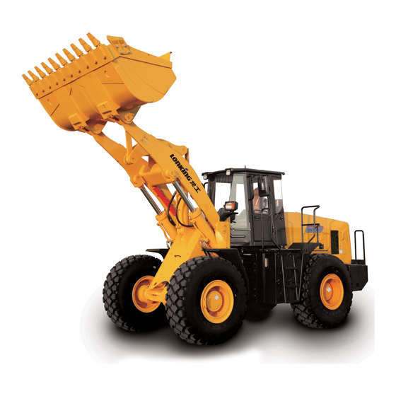
Thank you for choosing LONKING CDM816D wheel loader!
This Manual briefly describes safety instructions, performance parameters, structural principle and
requirements for operation, maintenance, adjustment and others of LONKING CDM816D wheel loader
for use and reference of machine operators, servicemen, and technical managers.
The Manual is the guideline for proper machine operation and maintenance; therefore, please read
carefully and comprehend the manual before machine application and operation and strictly follow the
corresponding instructions and requirements for machine operation, lubrication, maintenance and
repair. Many faults are resulted from human factors such as careless reading of Operation Manual;
High safety awareness and proper maintenance guarantee a safe and efficient operation, thus
benefitting you a lot. Therefore, please read and comprehend the safety instructions before operation
and strictly follow the relevant instructions and requirements. Incorrect operation, lubrication,
maintenance and repair are dangerous and may cause personal casualties.
Since we will continuously strive to improve product quality and synthesis performance to achieve
better cost performance and higher working efficiency, the information in this manual will be changed
without notice.
The technical parameters involved in this manual will not be taken as the inspection or test
basis of the third party.
In order to better service you and improve product and service quality, please inform us by
correspondence of the problems and improvement comments found when using LONKING products
and their Operation Manual.
This is the first edition.
Best wishes for your business!
LONKING (Shanghai) Road Construction Machinery Co., Ltd.
Jan. 30, 2012
Advertisement
Table of Contents

Related Manuals for Lonking CDM816D

Summary of Contents for Lonking CDM816D
- Page 1 Thank you for choosing LONKING CDM816D wheel loader! This Manual briefly describes safety instructions, performance parameters, structural principle and requirements for operation, maintenance, adjustment and others of LONKING CDM816D wheel loader for use and reference of machine operators, servicemen, and technical managers.
- Page 2 Some structures or accessories shown on photos or pictures in this manual may be different from those on your machine. In case of any doubts about the machine or this manual, please consult the LONKING dealers for the latest information.
-
Page 3: Table Of Contents
Contents Chapter I. Safety..................................................... 1 Safety instructions ............................1 Chapter II Applications, Main Technical Performance and Parameters ....................14 Applications ..............................14 Overallperformance parameters .......................... 14 III. Engine ..............................15 Powertrain ..............................15 Brakingsystem ............................. 16 Steering hydraulic system ..........................17 VII. -
Page 4: Chapter I. Safety
CDM816D WHEEL LOADER Chapter I. Safety Safety instructions Failure to follow or completely follow the basic safety regulations during the operation, maintenance or repair is the chief plotter for frequent accidents. Therefore, always keeping the safety awareness is a guarantee for accident elimination. - Page 5 It is a must to obtain the most accurate information and material about the machine before maintenance, repair or operation; in case of any difficulties hereinto, please consult the local LONKING sales-service department for those information or material. Prior to maintenance or repair, please carefully read and fully comprehend the relevant safety instructions;...
- Page 6 When servicing (refilling with) oil, never mix the oils at different grades and from different manufacturers together; it is a must to apply the LONKING special brake fluid, for the inacceptable brake fluid may lead tobrake locking, insufficient braking force or brake failure, thus causing machine non-operation and even safety accidents.
- Page 7 1.2.7 If the replaced part is applied with safety label, reapply the label on the new part. 1.2.8 Various brand-new safety labels are available at any LONKING after-sales facilities. 1.3 Understanding signal words 1.3.1 On safety labels, the words indicating the danger degree - DANGER, WARNING or CAUTION - are used together with the safety marks.
- Page 8 CDM816D WHEEL LOADER 1.3.3 “Caution” refers to the existence of potential dangers, which may cause light or medium injury if not avoided. Fig. 2 1.3.4 "Danger" or "Warning" safety labels are set near the specific hazard areas. For the conventional safety protections, see "Caution" labels.
- Page 9 Operation Manual Never stand under the lifted boom; or else, serious damages or even death are possibly caused. Fig. 3-1 Safety label of hinge (2) Label location: outside the main plate of front frame of loader Risk of crushing. Do not stand here when the vehicle makes turning.
- Page 10 CDM816D WHEEL LOADER Label for hydraulic oil (3) Label location: near the round dipstick of left hydraulic oil tank in the forward direction of overall unit. Refill with the hydraulic oil in time to avoid loader stop; incorrect oil filling may disenable or even damage the machine.
- Page 11 Operation Manual Label for preparation before start-up (5) Label location: left rear of cab seat Always operate the machine as per the label; otherwise, machine damage or personal injuries may be caused. Fig. 3-5 Labels of lifting (6) Label location: near the lifting eyes of front and rear frames For loader lifting, hang the hook into the lifting eye on the body and adjust the length of the lifting ropes before the lifting to keep the vehicle basically level;...
- Page 12 CDM816D WHEEL LOADER Warning labels of fan (7) Label location: both sides of rear engine hood Do not have your hands approach to the fan when the engine is running; otherwise, serious injury or death may be caused. Fig. 3-7...
- Page 13 Operation Manual Risk of explosion! Incorrect connection and jumper of wires may lead to explosion and personal casualties. Notice that the battery may be stored at different parts. Fig. 3-8 Tips for air reservoir application (9) Label location: beside the lifting eye of rear frame of overall unit Tips for air reservoir application During routine...
- Page 14 CDM816D WHEEL LOADER Refill with the fuel in time to avoid engine stop; incorrect oil filling may disenable and even damage the machine. Fig. 3-10 Label of regular check and maintenance requirements (11) Label location: on window at the right side of cab in the forward direction of overall unit...
- Page 15 Special transmission and torque converter oil The fault due to the application of oil not (8# hydraulic transmission oil) specified by LONKING is out of the range of Special hydraulic oil (46# anti-wear hydraulic warranty. oil) It is prohibited to mix two oils at different...
- Page 16 CDM816D WHEEL LOADER and air. Check the monitoring instrument for normal ● ● ● ● ● ● ● operation. Check the parts for abnormal noise and ● ● ● ● ● ● ● overheating. Check the tyres for pressure, crack or ●...
- Page 17 Operation Manual 1.5.2.1 In the operation of machine, do not wear loose clothes or jewels which may enmesh or lock the control handle or other parts on the equipment. 1.5.2.2 Make sure that all guard plates and covers are fixed on the corresponding locations of the equipment.
- Page 18 CDM816D WHEEL LOADER the storage location of fire extinguisher and be familiar with the use method. 1.5.4 Entry intocab 1.5.4.1 Before entering the cab, remove the sludge and fine sands on the shoes which will accumulate on the supporting points of throttle pedal and brake pedal and impede the pedal reset and may speed up the wear of pushing lever.
- Page 19 Operation Manual 1.5.8.3 Unless otherwise indicated, never make any adjustment when the machine is moving or the engine is running. 1.5.8.4 The gap of link mechanism for controlling the equipment may change with the movement of equipment or machine. Stay away from the area where the gap may change suddenly due to the movement of machine or equipment.
- Page 20 CDM816D WHEEL LOADER 1.5.10 Pipeline 1.5.10.1 Do not bend or knock the high-pressure pipelines. Do not install any bent or damaged pipeline. 1.5.10.2 Repair all loose or damaged pipelines. The leakage may cause fire. Consult the LONGKING agents about the matters for repairing or replacing the parts.
- Page 21 Operation Manual Come down from the machine. 1.5.12.4 In case of lightning, do not leave the cab or be sure to stand away from the machine. 1.5.13 Start of engine 1.5.13.1 If a warning label is attached on the start switch or control device, do not start the engine or pull the control device.
- Page 22 CDM816D WHEEL LOADER 1.5.16.4 Unless there are additional seats and seat belts on the machine, it is not allowed to carry people. 1.5.16.5 In the operation of machine, pay attention to and report where is in need of repair. 1.5.16.6 Do not come near the edge of the cliffs, tunnels and precipices.
- Page 23 Operation Manual machine and identify the potential danger. 1.5.19.3 In the operation on the slope, you shall consider the following important factors: At the higher speeds, the stability of the machine will deteriorate due to the inertia; In the rugged terrain, the stability of the machine will deteriorate; Machine will slip on the meadow, muddy road and gravel road;...
- Page 24 CDM816D WHEEL LOADER system pressure to the system set value and then release the pressure and drain the oil back to the hydraulic oil tank) to heat the hydraulic oil, which can ensure good response of the machine and prevent malfunction.
- Page 25 Operation Manual repeatedly depress the pedal; 1.5.23.11 The braking capacity of the brake is limited. To ensure safety, when the vehicle walks down the slope, never shut the engine down, perform gear shift or put the transmission in neutral position, but use the engine as the brake; Battery: ★...
- Page 26 CDM816D WHEEL LOADER frozen electrolyte and check for leakage; 1.5.23.16 Cause of electricity insufficiency of battery The machine is parked for long, the leakage current is too high or additional electrical equipment is applied, causing battery discharging; Abnormal operation such as switching on the electrical equipment for too long while the machine is not started;...
- Page 27 Operation Manual It is recommended to use a charger with 16.0 V constant voltage (no more than 16.2 V, otherwise most of the water in the electrolyte will be electrolyzed, thus resulting in dropped level, whitened charge indicator, or scrapped battery) and 25 A limited current to charge the battery until the indicator turns green, which means the charging is done;...
-
Page 28: Chapter Ii Applications, Main Technical Performance And Parameters
Chapter II Applications, Main Technical Performance and Parameters Applications CDM816D wheel loader is a multi-purpose construction machinery mainly used for spading, loading and transporting loose materials, applicable for the national defense, mine, water conservation, infrastructure, freight yard, road construction, port and wharf, and capable of loading, transportation, bulldozing, excavating and lifting. -
Page 29: Engine
CDM816D WHEEL LOADER Wheel track 1400 Min. ground clearance Max. dumping height (dumping distance ≥841) 2700 10. Steering angle (º) ±35 11. Operating weight (kg) 5500 III. Engine 1. Model: YT4A2-24 2. Type: In-line, water-cooled, direct injection Number of cylinders - bore × stroke (mm)... - Page 30 Operation Manual Torque converter outlet oil pressure (Mpa) 0.20-0.30 Max. allowabletorque converter outlet temperature (℃) Max. efficiency 0.82 2. Transmission Type Fixed-shaft hydraulic shift Gears Two forward gears and two reverse gears Gear ratio Forward gear I 2.47 Forward gear II 0.88 Reverse gear I 2.52...
-
Page 31: Brakingsystem
CDM816D WHEEL LOADER V. Brakingsystem 1. Foot brake Type Air booster caliper disc four wheel brake Brake disc diameter (mm) Φ410 Brake piston diameter (mm) Φ75(4 PCS) Workingair pressure (Mpa) 0.7-0.78 Braking oil pressure (Mpa) 9.8MPa Braking torque (N.m)/PCS 4300 2. -
Page 32: Electrical System
Operation Manual VIII. Electrical system System voltage (V) Battery (2 sets) Model Rated voltage (V) Rated capacity (Ah) Bulb voltage (V) (DC) Diesel engine starting (V) 24V(DC)electrical starting... -
Page 33: Chapter Iii Operation
Operation Manual Chapter III Operation Control mechanism and instrument 1. Hand brake 2. Control lever of tilt cylinder 3. Control level of boom cylinder 4. Steering lamp/ headlamp/ instrument lamp switch 5. Ignition start switch 6. Flameout cable 7. Accelerator pedal 8. -
Page 34: New Vehicle Running-In
CDM816D WHEEL LOADER Stop Release Fig.2-2 Hand brake control Floating Lowering Boom control lever in neutral position Lifting Bucket tilting forward Tilt control lever in neutral position Bucket tilting backward Fig. 2-3 Working device control II. New vehicle running-in The new vehicle must first undergo a running-in period and during this period, use and maintenance shall be paid attention to according to the following specifications. -
Page 35: Operation Of Wheel Loader
Operation Manual Please pay close attention to the temperatures of transmission, torque converter, front and rear axles, wheel hub housing as well as brake disc and brake drum. In case of overheat, identify the cause and perform troubleshooting. Check the tightening conditions of bolts and nuts at all positions. During the running-in period, porous materials loading are preferred, free from violent and sudden actions. - Page 36 CDM816D WHEEL LOADER During the driving, the forward gear shifting can be made without stopping the vehicle and stepping down the brake pedal. When shifting from low speed to high speed, the throttle pedal shall be firstly released and the gear lever shall be operated at the same time, and then the throttle pedal shall be stepped down;...
- Page 37 Operation Manual For rated speed: 0.35-0.5 Transmission and Torque Converter Pressure (MPa): 1.2-1.5 Max. temperature (℃) <120°C Braking system (Mpa) Min. pressure: 0.44 Working air pressure: Ammeter indication The pointer swinging to the left (-) (negative scale direction) indicates battery discharging; when the engine is started, the pointer swings to the left.The pointer swinging to the right (+) (positive scale direction) indicates that the engine is charging the battery.
- Page 38 CDM816D WHEEL LOADER minerals and tends to generate the scale in the water chamber of diesel engine, affecting the cooling effect and causing the malfunction, consequently, it is not preferred or shall be softened prior to use. For the diesel engine used in cold area or in winter, the antifreeze fluid can be added to the coolant, so as to prevent the coolant freezing after stopping of the vehicle.
- Page 39 Operation Manual (3) Check oil pipes, water pipes, air pipes and accessories for leakage. (4) Check if the transmission, torque converter, hydraulic oil pump, steering gear and front and rear axles are properly fixed, sealed, and too hot. (5) Check if rim bolt, transmission shaft bolt and pin shafts are loose. (6) Check if the working device is normal.
- Page 40 CDM816D WHEEL LOADER Operation mode (1) Loading Generally, loading can be done in the following two ways: As shown in Fig. 2-4 (A), the distance between (1) and (2) is 10m, and the freight vehicle shall be stationaryto ensure higher operation efficiency.In Fig. 2-2 (B), the loader and the freight vehicle are combined to perform the operation, which is appropriate for continuous transport of the fleet.
- Page 41 Operation Manual Fig. 2-5 (3) Handling Self-handling is adopted in the following cases: ① The road is soft, the place is not flattened, and it is impossible to use freight vehicle. ② The handling distance is within 500m and it is a waste of time to handle with freight vehicle. The handling speed depends on the road conditions.
- Page 42 CDM816D WHEEL LOADER Fig. 2-6 (5) Push-transportation ① Make the bucket press closely against the ground. ② Depress the throttle to move ahead, and if the loader is found to be hindered by obstacles, slightly lift the boom and move on. When lifting or lowering the boom, the control lever shall be between the lowering and lifting positions but not at the lifting or lowering position, to ensure the smooth operation, as shown in Fig.2-7:...
-
Page 43: Lubrication
Operation Manual ② For hard pavement, the boom control lever shall be in the floating position, and for soft pavement, it shall be in the neutral. ③ Engage the reverse and level the ground with the scraper. (7) Traction ① Securely fix the towing tractor to towing pin. ②... - Page 44 CDM816D WHEEL LOADER Drive axle oil Add the oil from the oil filler on left and right wheel housings until the oil spills when the oil plug in the middle of axle housing is open.The oil is used to lubricate the main reducer and hub reducer.
-
Page 45: Chapter Iv Structures Of Main Components
Operation Manual Chapter IV Structures of Main Components Diesel engine For detail descriptions, see Operation and Maintenance Manual for the diesel engine provided for this model. Notes: When the loader shall travel for long distance or stops with antifreeze fluid not filled in the coolant during cold weather (the ambient temperature is below the freezing point), switch on the water draining switches for diesel engine body, water pump, oil cooler, water tank lower chamber and torque converter oil cooler to drain out the water to avoid frost crack. -
Page 46: Transmission
CDM816D WHEEL LOADER reduction of gear shifts substantially reduce the driver’s labor intensity and increase the comfort. (ii) Working principle: The torque converter comprises pump pulley, turbine and guide wheel. The working chamber is filled with working oil. The pump pulley is used to transform the mechanical energy from engine into the kinetic energy of liquid. - Page 47 Operation Manual 1. Engine 2. Hydraulic torque 3. Transmission 4. Hand brake 5. Wheel converter Wheel-side 7. Differential 8. Drive axle 9. Main drive 10. Propeller shaft reducer The transmission is mainly composed of transmission housing, 4 gearshift clutches (i.e. forward clutch, reverse clutch, gear I clutch and gear II clutch), transmission control valve, oil filter as well as shaft and gear. ...
-
Page 48: Drive Axle
CDM816D WHEEL LOADER up to get a stable control of oil pressure (1.2~1.5 MPa). The oil returned from torque converter flows into the cooler for cooling at first and then into the transmission for lubrication and cooling through lubricating oil pressure valve which has a pressure of 0.10~0.20 MPa (1-2kg/cm... - Page 49 Operation Manual Fig. 3-4 Schematic Diagram of Working Principle of Axle The main engine torque is transmitted from drive axle input flange through transmission shaft. After reduction by main reducer, it changes the rotation direction to drive the driven spiral bevel gear and differential housing to rotate.
- Page 50 CDM816D WHEEL LOADER be adjusted through increasing/reducing the number of adjusting shims at bearing bush and of the adjusting nuts at the bearings on both sides of the differential. Adjustment of wheel-side hub bearing clearance: Tighten the round nut until the hub can rotate hardly, and then turn the round nut by 1/10 circle reversely.
-
Page 51: Hydraulic Steering System
V. Hydraulic steering system The single pump split-flow structures are adopted for the CDM816D hydraulic steering system and working device hydraulic system. The hydraulic steering system is mainly composed of full hydraulic steering gear, pilot valve, steering cylinder, gear pump, oil pipe and oil tank. See Fig. 3-5 Schematic... - Page 52 移至P48页,图的下方! CDM816D WHEEL LOADER Fig. 3-5 Schematic Diagram of Hydraulic Steering System Working principle of steering system The pressure oil from oil pump first flows into the pilot valve which distributes oil flow to steering gear preferentially no matter how high or low the load, pressure and steering wheel speed are, or whether the engine is idling or running at high speed, so as to ensure sufficient oil supply for steering and stable and reliable steering actions.
-
Page 53: Implementhydraulic System
Operation Manual groove, then to the distributing groove of the valve core, to the load ring groove of the valve sleeve and finally to the load port of the valve body. It is connected with pilot valve through pipeline to get ready to transmit the steering pressure signal. - Page 54 CDM816D WHEEL LOADER Oil from priority valve EF port Fig. 3-7 Schematic Diagram of Implement Hydraulic System Working principle The engine operation is realized by driving the gear via torque converter. When two control levers are at neutral positions, the tilt valve stem and the boom valve stem of the multi-way valvewill be also at the neutral positions.
- Page 55 Operation Manual multi-way valve to push the cylinder piston move up, so as to realize lifting. Meanwhile, the oil in the small chamber of the lifting cylinder returns to the oil tank through the multi-way valve. When the control lever is at neutral position, the boom valve stem is kept at the neutral position under the action of the return spring.
- Page 56 CDM816D WHEEL LOADER Fig. 3-8 Boom Cylinder Tilt cylinder: Spring Support Cylinder O-ring Guide Piston O-ring Support Piston Holeelastic Dust ring retainer knuckle ring block sleeve ring circlip ring bearing Fig. 3-9 Tilt Cylinder Multi-way valve (duplex): Return valve Filling...
- Page 57 Operation Manual The A1 port of tilt valve is provided with an overload valve and its pressure is set to 12MPa; the B1 port is equipped with an overload filling valve and the overload pressure is set to16MPa; The schematic diagram of interior structure is as follows: The oil circuit controlled by this valve is designed with a series structure and is used to control the movement direction of tilt cylinder and boom cylinder by changing the oil flow direction to keep each part at a fixed position, thus meeting various operation requirements for engineering machinery.
- Page 58 CDM816D WHEEL LOADER Move the boom slide valve right to close “T” chamber and the hydraulic oil flows to “a” port from “P1” chamber to open the one-way valve and then into the lower chamber through “A ” port to lift the boom.
- Page 59 Operation Manual Move the tilt slide valve right (as shown in the Fig..) to close “P ” chamber and “T” chamber and the hydraulic oil flows to “c” port from “P” chamber to open the one-way valve and then into the rear cylinder chamber through “A ”...
-
Page 60: Implement&Frame
CDM816D WHEEL LOADER Fig.3-17 Interior Structure of Overload Filling Valve The oil tank (see Fig. 3-18), with a capacity of 80L, is shared between the working device and steering system. Air filter used to refuel is on the top, two joints used to fit hydraulic system inlet/return pipe are located in the left, and two oil filters are fitted to the inside to remove impurities in the oil. - Page 61 Operation Manual performs “Z” shaped reverse tilt. It is characterized by large unloading height, high breakout force and large bucket up-tilt angle, good lateral movement ability, easy fill-up and little material falling during lifting. When the boom is lowered directly to the lowest position after unloading at the highest position, the bucket will be automatically switched to cut-in state. ...
-
Page 62: Braking System
CDM816D WHEEL LOADER steering mechanism, front and rear frames rotate around the articulating axis to realize steering. Rear frame and oscillating frame are connected through articulating pin. The oscillating frame can swing up/down by 10° around the pin center so as to make the loader remain stable even when traveling on rough roads. ... - Page 63 Operation Manual Rear booster pump 5. Foot brake master valve 6. Front booster pump Fig. 3-21 Service brake system The system structure is shown in Fig. 3-21. The compressed air from air compressor driven by engine flows into air reservoir (1) through the relief valve (2) and the system pressure is 0.7~0.78MPa. One port of the air reservoir is connected to the air inlet of air brake valve (5).
- Page 64 CDM816D WHEEL LOADER Air outlet C Air discharge port F Fig. 3-22 a. One-way valve b. Diaphragm d. Pressure regulating valve assembly e. Exhaust valve stem f. Exhaust valve Working principle: As shown in Fig. 3-22, the compressed air from air compressor flows into chamber (B) through air inlet (A) and then to air outlet (C) through one-way valve (a) to charge the air reservoir.
- Page 65 Operation Manual Fig. 3-23 Air brake master valve 1. Adjusting screw 2. Pedal 3. Mandril 4. Balance spring 5. Return spring 6. Piston 7. Air intake valve Air outlet Air discharge port Working principle: As shown in Fig. 3-23, when the brake pedal (2) is stepped down, it applies a certain pressure to the balance spring (4) through the mandril to push the piston (6) down to close the passage connecting the air outlet and atmosphere and to open the air intake valve so that the compressed air is charged into braking components through the air outlet and the air pressure at air...
- Page 66 CDM816D WHEEL LOADER Vacuum air hole Oilinlet Bleed screw Air inlet Oiloutlet Oil filling port Fig. 3-24 Working principle: The structure is shown in Fig. 3-24. The booster pump is a gas pushed oil booster comprising cylinder and hydraulic master pump. During working, the air entering through air inlet pushes the push rod piston assembly forward and the push rod pushes the push rod seat assembly.
- Page 67 Operation Manual water, otherwise, the rubber components of the system will be quickly damaged and the braking effect will be reduced. (3) The air in oil channel system will affect the braking performance, so air bleeding shall be carried out after part replacement and repair with the method as follows: Remove the sludge and scales at pipeline, oil storage chamber, oil filler and air bleeding location of the oil channel system;...
- Page 68 CDM816D WHEEL LOADER Parking brake system, or hand brake, consists of parking brake, control handle and flexible control shaft to park vehicle for a long time. Parking brake, also called center brake, is a self-servo two-shoe internal expanding brake and fitted to front output shaft of transmission. See Fig. 3-25 for the structure.
-
Page 69: Electrical System
Operation Manual regulation with the adjusting rod to meet the above requirements. IX. Electrical system The electrical system is composed of silicon rectification generator, regulator, starter (matching with diesel engine), battery, lighting system, oil circuit pressure, oil temperature and cleanliness monitoring systems, low pressure alarm and instruments. ... - Page 70 CDM816D WHEEL LOADER Use and Maintenance of the Supporting Battery in the Loader and Related Notes After the battery is installed in the whole loader, since the circulation time of the new loader in and out the factory differs, the actual charge capacity of the battery and the discharging degree are also...
-
Page 71: Lubrication
Operation Manual Always prevent impact on the battery causing fracture to its case during removing and installing. The battery is equipped with a plastic case which can bear limited pressure and tension force on four edges due to its plasticity. The fixed locking bolt of the battery shall not be fastened tightly to avoid leakage of battery acid solution due to the splitting of seals around the battery case. -
Page 72: Regular Maintenance
CDM816D WHEEL LOADER Oil for steering system and working hydraulic system Add oil from the oil filler at the engine oil tank until the oil pointer in the tank points between the upper and lower oil pointer holes. The oil is used by the system as pressure oil produced by the oil pump. For the steering gear, add oil from the oil filling pipe to lubricate the recirculating ball pair. - Page 73 Operation Manual out to be more convenient and the numbers included in calendar time-based plans are approximate to those in the corresponding work time-based plans. Carry out maintenance work, no matter what time is adopted, work time or calendar time, whichever comes first; It is necessary to shorten time specified in the maintenance cycles table and carry out maintenance more frequently under the extremely harsh, dusty, wet, or other unfavorable working conditions;...
- Page 74 CDM816D WHEEL LOADER Check and add the brake-fluid of the machine. (Note: A brake-fluid of the same model as the original fluid must be used. Otherwise, the original fluid must be completely emptied through a port near the brake caliper and add a new brake-fluid);...
- Page 75 Operation Manual element, the original hydraulic oil must be filtered or replaced) Maintenance items to be performed once every 500 hours or every three months Tighten the bolts for connecting the front/rear axle and the frames, and the plate bolts for articulating the front and rear parts of the frame.
- Page 76 CDM816D WHEEL LOADER Check the seal of the distribution valve and working cylinder, and repair or replace them if necessary. Check the working condition of torque converter and transmission, repair them if necessary. IX. Maintenance item to be performed once every 6000 hours or every three years.
- Page 77 Operation Manual Attachment 1 Machine No.: Registration Table for Phase-by-phase Checking and Maintenance of the Loader Brief Work Check Checked 50h 100h 250h 500h 1000h 2000h 4000h 6000h 10000h defect time date description ● 100h ● ● 150h ● 200h ●...
- Page 78 CDM816D WHEEL LOADER Attachment 1 Machine No.: Registration Table for Phase-by-phase Checking and Maintenance of the Loader Brief Work Check Checked 50h 100h 250h 500h 1000h 2000h 4000h 6000h 10000h defect time date description ● ● 2250h ● ● 2300h ●...
- Page 79 Operation Manual Attachment 1 Machine No.: Registration Table for Phase-by-phase Checking and Maintenance of the Loader Brief Work Check Checked defect 50h 100h 250h 500h 1000h 2000h 4000h 6000h 10000h time date description ● ● 4200h ● ● 4250h ● ●...
- Page 80 CDM816D WHEEL LOADER Attachment 1 Machine No.: Registration Table for Phase-by-phase Checking and Maintenance of the Loader Brief Work Check Checked 50h 100h 250h 500h 1000h 2000h 4000h 6000h 10000h defect time date description ● 6150h ● ● 6200h ●...
- Page 81 Operation Manual Attachment 1 Machine No.: Registration Table for Phase-by-phase Checking and Maintenance of the Loader Brief Work Check Checked 50h 100h 250h 500h 1000h 2000h 4000h 6000h 10000h defect time date description ● ● 8100h ● 8150h ● ● 8200h ●...
-
Page 82: Chapter V Instructions For Loader Fixing In Hoisting And Transportation
CDM816D WHEEL LOADER The Chinese and Foreign Oil Type List for Wheel Loader International standard serial number and Oil Name Chinese standard serial number and type type Engine Oil LOW temperature CD 5W/40 or CD OW/40 LOW temperature CF-4 5W/30... -
Page 83: Fixing Of Loader In Transportation
Operation Manual Fig. 5-1 II. Fixing of loader in transportation When a flat car or similar transportation facility is applied for loader transportation, it is required to fix the chassis of the loader with iron chain so as to prevent it from shaking and bouncing; it is necessary to fasten the fixing rods of the front and rear frames, fix the front and rear wheels with angle steel, and then tie up with steel wire to prevent the machine from moving back and forth on the flat car. -
Page 84: Shipping Of Loader
CDM816D WHEEL LOADER III. Shipping of loader When the loader is required to be packed for ocean shipping, remove the parts such as bucket, two fuel tanks and tyres (wheel rim).Fix the removed parts with shipping brackets, tie the body, boom and pull rod to the brackets, and place and fix other removed parts according to the loading of the container. -
Page 85: Chapter Vi Common Faults And Solutions
Operation Manual Chapter VI Common Faults and Solutions Faults Features Causes Solutions No gear is engaged Transmission oil level is too Engage a gear again and readjust The brake lever of gearshift the gearshift control lever control lever valve can mot return Add oil to the specified level Started diesel engine to the original position... - Page 86 CDM816D WHEEL LOADER Faults Features Causes Solutions Oil deterioration remove the fault Check and clean the transmission oil radiator Check if the oil for dual-clutch transmission (oil quantity and quality) meets the requirement Check if the oil return pressure of the...
- Page 87 Operation Manual Faults Features Causes Solutions Worn or damaged oil seal of Replace the oil seal oil cylinder Remove, overhaul and repair to get distribution valve the clearance to the specified value and excessively worn, fitting replace the distribution valve clearance between the valve rod Find out the oil leakage and remove and valve body exceeds the...
- Page 88 CDM816D WHEEL LOADER Faults Features Causes Solutions leather ring are easy to be worn hydraulic leather ring The piston gets stuck Replace the whole piston Air in the hydraulic pipeline Exhaust the air in the hydraulic does exhausted pipeline completely...
-
Page 89: Attached Table:reference Table For Densities Of Common Materials
Operation Manual Attached Table:Reference Table for Densities of Common Materials Reference Density Material name Specific Categories Remarks (Kg/m Stick thin dry soil 1250 Caking dry soil 1520 Powder dry soil 1550 Ordinary soil Wet soil 1725 Mud-like soil 1730 Tight soil 1840 Wet clay 1750...
Need help?
Do you have a question about the CDM816D and is the answer not in the manual?
Questions and answers