Table of Contents
Advertisement
Quick Links
PREFACE
Thank you for purchasing LONKING's high-performance wheel loader!
This Manual briefly describes the safety, operational and maintenance requirements of
LG833NG (LG833BGIII.00I) wheel loaders for the use and reference by operators,
maintenance and technical management personnel.
User Manual is a guide for proper use and maintenance of this machine. Please carefully
read and understand the contents of this Manual before operating this machine.
Please put this Manual in driver's cab for convenience of reference at any moment. If you
lose this Manual, please contact our sales department for buying a new one.
Many failures arise as a result of operator's failure to carefully read this Manual and other
human reasons. A high sense of safety and good maintenance enable the safe and
efficient operation of this machine, thus bringing you more benefits. Therefore, please
read and understand safety instructions before operating this machine and fully comply
with them. Improper operation, lubrication, maintenance and repair of this machine are
dangerous and may result in human casualties.
We will continue to increase the working efficiency of the machine by improving product
design and endeavoring to improve the comprehensive product performances. The
parameters and configurations of the machine in this Manual are subject to change
without notice. The technical parameters contained herein shall not serve as the basis for
any inspection or test.
In order to offer better services to you and improve product and service quality, you are
expected to timely inform us of any problem identified during your use of LONKING
products and this Manual, along with any corresponding improvement opinions.
This Manual is its first version.
Best wishes for your business!
LONKING Holdings Limited
June 2015
Advertisement
Table of Contents

Related Manuals for Lonking LG833NG

Summary of Contents for Lonking LG833NG
-
Page 1: Preface
In order to offer better services to you and improve product and service quality, you are expected to timely inform us of any problem identified during your use of LONKING products and this Manual, along with any corresponding improvement opinions. -
Page 2: Table Of Contents
CONTENTS PREFACE............................1 CONTENTS............................2 CHAPTER I SAFETY PRECAUTIONS................7 DESCRIPTION OF SAFETY SIGNS..............7 DESCRIPTION AND LOCATIONS OF SAFETY SIGNS.......7 1.2.1 WARNING SIGN OF REVERSING............8 1.2.2 WARNING SIGN OF THE ANTI- FREEZE FLUID......8 1.2.3 WARNING SIGN OF MAINTENANCE AND TRANSPORTATION...8 1.2.4 WARNING SIGN OF LIFT ARM............. - Page 3 1.4.10 FIRE EXTINGUISHER AND FIRST-AID KIT........22 1.4.11 PREVENTION OF ROLLING INJURY OR CUT OFF....22 1.4.12 ETHER (IF YOUR MACHINE IS EQUIPPED WITH ETHER COLD STARTING DEVICE)........23 1.4.13 MAKE SURE A GOOD VENTILATION WHEN OPERATING IN AN ENCLOSED SPACE..............23 1.4.14 PIPELINE, HARD PIPE AND FLEXIBLE PIPE.......
- Page 4 PRECAUTIONS OF TIRE STORAGE..........50 CATALOG AND REPLACEMENT CYCLE OF CRITICAL SAFETY PARTS.................... 50 CHAPTER II OPERATION AND CONTROL..............52 MAIN PERFORMANCE PARAMETERS AND SPECIFICATIONS....53 OUTLINE DRAWING OF LG833NG (LG833BGIII.00I) WHEEL LOADER....................56 PURPOSE......................57 CHAPTER III OPERATION INSTRUCTIONNS..............58 STEERING WHEEL..................58 NEGATIVE-POLE SWITCH OF BATTERY..........58...
- Page 5 3.12 USE OF CAB DOOR LOCK................70 3.13 USE OF LOCATING LOCK................70 3.14 ADJUSTMENT TO REAR-VIEW MIRROR..........70 3.15 CHARGING DOCK..................71 3.16 SUNSHADE...................... 72 CHAPTER IV OPERATION....................73 NOTICES ON OPERATION OF NEW LOADER........73 RUNNING-IN OF NEW LOADER..............73 4.2.1 REQUIREMENTS ON RUNNING-IN OF NEW LOADER....73 4.2.2 OPERATIONS TO BE CARRIED OUT AFTER EIGHT HOURS OF RUNNING-IN........
- Page 6 5.5.3 INSPECT COOLANT LEVEL REGULARLY........104 5.5.4 CLEANING OF COOLING SYSTEM..........104 5.5.5 ENGINE AIR FILTER MAINTENANCE........... 105 5.5.6 MAINTENANCE AND REPLACEMENT OF MAIN CORE OF THE AIR FILTER.......... 106 5.5.7 REPLACEMENT OF SAFE FILTER ELEMENT OF AIR FILTER108 5.5.8 CLEAN DUST COLLECTION CUP OF THE AIR FILTER..... 108 USE OF FUEL SYSTEM AND RELATED MAINTENANCE....
-
Page 7: Chapter Isafety Precautions
CHAPTER I SAFETY PRECAUTIONS Warning! Please read and understand all the safety precautions before operation. Failure to do so may result in severe bodily injury or death. 1.1 DESCRIPTION OF SAFETY SIGNS Danger! 1) There exists danger that may affect your personal safety. 2) Don’t operate the machine without permission. -
Page 8: Warning Sign Of Reversing
1.2.1 WARNING SIGN OF REVERSING Sign location: rear counterweight Contents: when driving the car backwards, the driver must pay attention to maintain a certain distance between the machine and surrounding staff to avoid accidents. When driving the car backwards, the driver must pay attention to the surrounding pedestrians and vehicles to avoid accidents. -
Page 9: Warning Sign Of Lift Arm
1.2.4 WARNING SIGN OF LIFT ARM Sign location: front end of lift arm Contents: this sign reminds user that never permit persons to stand below the moving lift arm when operating lift arm to avoid accidents. 1.2.5 SAFETY WARNING SIGN OF HINGE Sign location: in the front and rear hinging ... -
Page 10: Warning Sign Of No Trample
1.2.7 WARNING SIGN OF NO TRAMPLE Sign location: upper side of splash guard of front frame Contents: due to the limitation of bearing capacity of steel panel on splashguard, keep off here to avoid accidents. 1.2.8 DISTRIBUTING DIAGRAM OF GREASE NIPPLE AND LUBRICATING POINTS Sign location: left side of the frame hinge ... -
Page 11: Lifting And Binding Sign
1.2.11 HYDRAULIC OIL SIGN Sign location: on hydraulic oil tank Contents: this sign reminds the user that the filled hydraulic oil shall be the oil product designated by LONKING or the hydraulic oil of the same type. -
Page 12: Schematic Diagram Of Use Of Triangle Iron
1.2.12 SCHEMATIC DIAGRAM OF USE OF TRIANGLE IRON Sign location: on the triangle iron fixing bracket of front fender Contents: this signs reminds the user that if the machine stops on the slope or tires need to be fixed to prevent tires from moving, it is required to comply with the contents of this sign. -
Page 13: Attachment Nameplate
1.2.15 ATTACHMENT NAMEPLATE Sign location: on the bucket Contents: the description of the basic information of machine attachments. 型 号 属具重量 属具容量 属具宽度 系统压力 1.2.16 SIGN OF FLUSHER CONTAINER Sign location: on the engine hood of the cab Contents: this sign reminds the user that this ... -
Page 14: Safety Exit Sign
1.2.18 SAFETY EXIT SIGN Sign location: on the glass of the right door of the Contents: this sign reminds user that if the main exit is blocked, unhinge the latch and escape from the right door. 1.2.19 SCALDING WARNING SIGN AT HIGH TEMPERATURE PLACE Sign location: left and right sides of the ... -
Page 15: Remarks For Long Time Standstill
1.2.20 REMARKS FOR LONG TIME STANDSTILL Sign location: on rear hood Contents: this sign reminds the user to operate the machine according to this sign. Otherwise, it may cause machine damage or personal injury. 1.2.21 SIGN OF BATTERY CONNECTING WIRE ... -
Page 16: Combination Of Warning Signs
This warning sign reminds the user to use parts dedicated for Lonking loaders during replacement of parts; otherwise machine damage or personal accident may occur. This warning sign reminds the user to use oil... -
Page 17: Unauthorized Modification
1.3 UNAUTHORIZED MODIFICATION Any modification of this machine not authorized or approved in writing by LONKING may cause safety accidents. The owner shall bear all the consequences. For the sake of safety, please use correct grade and genuine fitting and oil. If without correct fittings or periodically fasteners change, the parts may exceed safety use limitation. -
Page 18: Safety Precaution For Internal Cab
1.4.3 SAFETY PRECAUTION FOR INTERNAL CAB Before entering cab, remove mud and oil dirt sticking to shoes bottom. Otherwise, it may cause an accident due to skidding when trampling the accelerator pedal or brake pedal. Do not adsorb suction cup stick on the cab glass, for the lens action of suction cup may cause fire accidents. -
Page 19: Working Clothes And Personal Protective Equipments
1.4.4 WORKING CLOTHES AND PERSONAL PROTECTIVE EQUIPMENTS Avoid wearing loose clothes and ornaments or other things that may hook control level or other machine parts, for they may be blocked or engulfed in control system or moving parts, and cause severe injuries or casualties. Do not wear greasy clothes to avoid catching a fire. -
Page 20: Fire Prevention Of Oil Products
When ascending or descending machine, it is prohibited to take any tools or other things. 1.4.6 FIRE PREVENTION OF OIL PRODUCTS Please use fuel, oil and hydraulic oil used in hydraulic system to fill diesel engine of this loader, hydraulic transmission oils and gear oils used in transmission system and brake fluid used in brake system and antifreeze used in engine water tank can be lit by open fires, in particular,... -
Page 21: Precautions When Operating At High Temperature
1.4.8 PROTECTION OF ASBESTOS DUST HAZARD Inhalation of asbestos dust may be harmful to body health. The products produced by LONKING Holdings Limited do not include asbestos, but if you contact with materials containing asbestos fibers, please follow the below rules: It is protective to use compressed air for cleaning. -
Page 22: Face Mask And Earplug
if possible, operate the machine in the uptake. If necessary, use qualified dust mask. 1.4.9 FACE MASK AND EARPLUG Never ignore the dangerous factors that may not be harmful to body health at present. Exhaust gas and noise is unseen, but it may cause disability or permanent injury. 1.4.10 FIRE EXTINGUISHER AND FIRST-AID KIT In case of personal injury or fire, please take aid actions according to the following measures:... -
Page 23: Ether (If Your Machine Is Equipped With Ether Cold Starting Device)
Properly support equipment or accessory when working underside the machine. Do not relay on hydraulic cylinder for supporting. If the control mechanism moves or hydraulic pipeline leaks, any attachment will fall off. Unless otherwise specified, make no adjustment when the machine is operating or the engine is starting. -
Page 24: Pipeline, Hard Pipe And Flexible Pipe
LONKING Holdings Limited. Please carefully check all pipelines, hard pipes and flexible pipes, tighten all joints according to specified tightening torque. Do not check the leakage with bare hands, but check them with board or cardboard. -
Page 25: Coolant
LONKING Holdings Limited for consultation repair method. When using breaker for operation, install a protective device on the front windshield. Please contact the designated dealer of LONKING Holdings Limited for recommendations. -
Page 26: Safety Precaution Of Operation
1.5 SAFETY PRECAUTION OF OPERATION 1.5.1 SITE SAFETY Before starting the engine, carefully check whether there is any abnormal condition around the engine that leads to dangerous situation. Check the site landform and ground condition; decide the best and safest operation method. -
Page 27: Check Before Engine Start-Up
1.5.2 CHECK BEFORE ENGINE START-UP Prior to operation, check the following items before the engine start-up. Otherwise, it may cause serious injuries or damages. Check whether there are flammable materials around engine or battery. Check whether there are leakages of fuel, oil or hydraulic oil. Check whether the rearview mirrors, armrests and ladders have stained by fuel. -
Page 28: Check After Engine Starting Up And Before Machine Operation
Only when the operator sitting down to the seat that can start and operate the engine. Make sure there is nobody in the cab except the operator. It is not allowed that anyone sits down on the body of the machine. If the machine has not used for a long time or the operating temperature is extremely low, please maintain your machine before start up. -
Page 29: Precautions When The Machine Begin To Run
1.5.5 PRECAUTIONS WHEN THE MACHINE BEGIN TO RUN Before operating the machine, again check the states around the machine, make sure there is nobody and obstacle there. When the machine is running, sound the horn for warning. Only when the operator sitting down to the seat that can start and operate the engine. -
Page 30: Check When Changing Direction
or operating. If the working condition is in water condition, it shall no exceed a permitted depth. When passing through a bridge or private structures, check whether their bearing capacities can support this machine. When walking on public road, firstly it shall be in comply with the provisions of related authorities and traffic laws and regulations. -
Page 31: Precautions When Traveling On The Slope
It is dangerous to work on the soft, uneven or cracked road, and may cause the machine crashed. It is also dangerous to walk with imbalanced load and non-load. 1.5.9 PRECAUTIONS WHEN TRAVELING ON THE SLOPE Be careful that the machine may dump or skid to one side when traveling on the slope. Keep a clearance of 200-300mm from the bucket to the ground when traveling on the slope. -
Page 32: Beware Of High Voltage Cables
1.5.10 BEWARE OF HIGH VOLTAGE CABLES Do not let the machine touch the overhead cables, even near the high voltage cable can cause electric shock. Keep a safe distance between the machine and cable as shown in the following table. For the prevention of accidents, please perform the following tasks: When there is a danger of touch the cable during... -
Page 33: Precaution For Operation
1.6 PRECAUTION FOR OPERATION Do not get close to the edge of a cliff. When the machine shoves the soil descending a cliff or onto the peak of the slope, the load will suddenly become lighter. In such case, due to a sudden increase in walking speed, it is dangerous;... -
Page 34: Precautions When Operating On Snowy Days
1.6.2 PRECAUTIONS WHEN OPERATING ON SNOWY DAYS When the machine working on the snowy or icy road, even a small slope can make the machine slide aside, therefore it is important to low the walking speed and avoid a sudden start, stop or sharp turn, because it has danger of sliding, especially when the machine is in uphill or downhill status. -
Page 35: Precautions When Parking The Machine
machine may collapse the soft soil that cause machine turnover. When there is danger of falling rocks at site, the machine shall be equipped with falling objects protection device (FOPS). When there is danger of falling rocks and potential turnover trend at site, install falling objects protection device (FOPS) and tie the safety belt. -
Page 36: Precautions Of Machine Transportation
When the machine walking on the public road, first check whether it is in comply with the provisions of relevant authorities and follow those provision requirements. The machine may need to divide into several parts for the convenience of transport. For the division of this machine, please consult the designated dealer of LONKING Holdings Limited. 1.6.8... -
Page 37: Precaution For Use And Maintenance Of The Battery
If there are some problems such as failing to start the machine or braking system, please contact the designated dealer of LONKING Holdings Limited for repair. It is dangerous to drag the machine on the slope, therefore it is right to choose a flat gradient place, if this place is not available, choose a place as small angel as possible to drag the machine. -
Page 38: Precatution For Start-Up With Booster Cable
unexpected contact with the battery, because it may cause short-circuit between the positive (+) and negative (-) terminal. When installing battery, first connect positive (+) terminal, while demounting battery, first shut down negative (-) terminal (ground side). When amounting or demounting battery, first identify which is positive (+) terminal and which is negative (-) terminal, and tighten the nuts firmly. -
Page 39: Precautions For Battery Charge
1.7.1 FAULT NOTIFICATION If processing maintenance has not mentioned in User Manual, it can lead to unexpected fault. Then please contact to designated dealer of LONKING Holdings Limited for repair. 1.7.2 CLEANING BEFORE REPAIR AND MAINTENANCE It needs to clean up the machine before repair and maintenance. -
Page 40: Keep Cleanness Of Workplace
from the wet or oil surface. 2. When using high-pressure water to wash machine, please wear protective clothing to avoid the impact of the high-pressure water, such as hurting the skin or wastes, mud splashed into the eyes. 3. Prohibit water spray onto components of the electrical system (like sensor, wiring plug connector), so as to avoid water from going into... -
Page 41: Operating Before Repair And Maintenance
1.8 OPERATING BEFORE REPAIR AND MAINTENANCE Before repair and maintenance, park the machine on the level ground where there are no falling stones or landslides. If parking is in a lower position, there shall be no danger of flood, and then shut down the engine. -
Page 42: Regular Replacement Of Critical Safety Parts
Certain technology is necessary to replace the critical safety parts. Please contact the dealer of LONKING Holdings Limited to do so. Critical safety parts will go aging with time and oil leakage will lead to serious accident;... -
Page 43: Persons For Repair And Maintenance
Fuel, lubricant and the other inflammable should be stored far away from open fire. Do not use diesel or gasoline, for it has risk of lighting; use incombustible material as detergent for cleaning the parts. Smoke at the designated place. Smoking is prohibited when overhaul or maintenance is performed. -
Page 44: Frame Maintenance With The Working Device Supported Up
1.8.9 FRAME MAINTENANCE WITH THE WORKING DEVICE SUPPORTED When the frames are maintained with the working device lifted, it is necessary to lock up the front and rear frames with the frame fixing rods. Set the joystick to the “neutral” position, lock up joystick with locking equipment, and then support the working device with supporting rods. -
Page 45: Maintenance When Engine Is Working
1.8.11 MAINTENANCE WHEN ENGINE IS WORKING To avoid hurting, do not conduct maintenance when the engine is running. Be sure to comply with the following items for maintenance when the engine is running: To arrange one worker sitting in the operator seat, and ready to shut down the engine at any necessary moment. -
Page 46: Precautions In The Use Of Hammer
inside of the machine. During maintenance, do not carry any unnecessary tools and spare parts in the pockets. 1.8.13 PRECAUTIONS IN THE USE OF HAMMER When using a hammer, be sure to wear safety glasses, safety helmets and other protective clothing, and place a brass rod between the hammer and area being hammered. -
Page 47: Fill Of Fuel Or Lubricating Oil
Please consult the designated dealer of LONKING Holdings Limited for repair according to the fault types. 1.8.17 FILL OF FUEL OR LUBRICATING OIL Fuel, lubricating oil, hydraulic oil, antifreeze, brake fluid, window glass detergent can be ignited by flame. Therefore please comply with... -
Page 48: Prevention Measures Of Maintenance In High Temperature Or High Pressure
If the leaking place is difficult to identify, please contact with designated dealer LONKING Holdings Limited about repair issues. Do not use bare hands to check for leakage, but to use the board or cardboard to check for leakage. -
Page 49: Precautions Of Tire Maintenance
regulations. 1.8.22 PRECAUTIONS OF TIRE MAINTENANCE Tire filled with gas explodes for the inner gas is overheated, commonly due to heat from welding or wheels rim, external fire or brake too often. Tire explosion is so powerful which can cause tire, wheel rim, and eventually transmission parts flying 500 meters away from the machine. -
Page 50: Precautions Of Tire Storage
If pipe clamp used to fix the tube has any damage, such as distortion or crack, it shall be changed with the tube. When replacing tube, be sure to replace O-ring, gasket and parts like this at the same time. Please contact designated dealer of LONKING Holdings Limited to replace critical safety parts. - Page 51 REGULAR REPLACEMENT TABLE OF CRITICAL SAFETY PARTS Critical parts needed regular Quant Replacement cycle replacement Each year or 2000 hours (whichever Filter element of hydraulic oil tank is earlier) Hose from fuel coarse filter to fuel tank Hose from fuel coarse filter to diesel engine inlet Diesel engine oil return hose Fuel tube (feed pump-diesel oil filter)
-
Page 52: Chapter Ii Operation And Control
CHAPTER II OPERATION AND CONTROL Right Frame Cylinder Rocker arm Front Lift arm Rear Bucket Balance weight Front wheel Rear wheel Left Schematic Diagram of Components of Wheel Loader... -
Page 53: Main Performance Parameters And Specifications
2.1 MAIN PERFORMANCE PARAMETERS AND SPECIFICATIONS LG833NG (LG833BGIII.00I) STANDARD SPECIFICATIONS ITEM SPECIFICATION Rated bucket capacity 1.7 m Rated payload 3000Kg Lifting time ≤5.5 s ≤10.5 Total hydraulic cycle time Forward IV 36km/h Forward III 24km/h Forward II 12km/h Maximum speeds... - Page 54 ITEM SPECIFICATION WP6G125E22 Type 92kw/2200r·m Rated speed Maximum torque 500 /1400~1600 (Nm/r·m ) Fuel consumption ratio under rated working 225g/kw·h condition (bench test) Fuel type (according to ambient temperature) 0# light diesel oil Fan diameter (blow air backwards) φ600mm Type Single stage, single phase, three elements Hydraulic torque Conversion ratio...
- Page 55 ITEM SPECIFICATION Type Fully hydraulic load sensitive Number of steering cylinders-cylinder bore × 2-φ80X315mm stroke(mm) Steering pump Used with working pump Working pressure 14MPa Left/ right 35° Steering angle 2-φ125×784mm Number of lift arm cylinders--cylinder bore × stroke 1-φ140×553mm Number of bucket cylinders--cylinder bore × stroke Distribution valve Multi-way valve Model...
-
Page 56: Outline Drawing Of Lg833Ng (Lg833Bgiii.00I) Wheel Loader
2.2 OUTLINE DRAWING OF LG833NG (LG833BGIII.00I) WHEEL LOADER... -
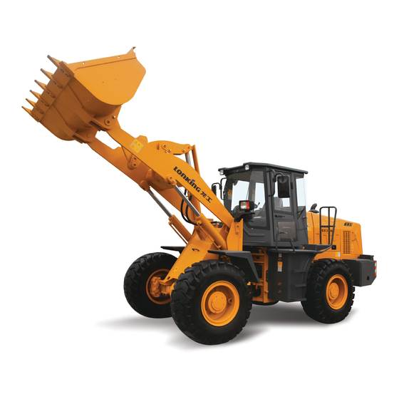
Page 57: Purpose
2.3 PURPOSE LG833NG articulated wheel loader is a medium-sized loader and mainly used for handling bulk materials. It is an efficient and multi-functional engineering machine. The loader is widely used for loading, bulldozing, shoveling, traction, lifting and transportation in mines, civil works, road constructions, harbors and goods yards. -
Page 58: Chapter Iii Operation Instructionns
CHAPTER III OPERATION INSTRUCTIONNS 3.1 STEERING WHEEL The articulated loader uses fully hydraulic power steering. The steering wheel is arranged inside the Cab and connected to the full-hydraulic redirector. Turning clockwise the steering wheel turns the loader right; turning counterclockwise the steering wheel turns the loader left. -
Page 59: Starter Switch
electrical system of loader, turn the battery negative-pole switch handle counterclockwise to “OFF” position. The handle is parallel to the frame plane. Turn on the battery negative-pole switch : Before starting the loader, it is necessary to turn negative-pole switch handle clockwise to “ON”... -
Page 60: Service Brake Pedal
energized. 4. START--Insert the starter switch key and clockwise turn it to the second position “START”. With the key at “START” position, the motor is energized to start the engine. Immediately release the key after the engine has been started, the key will automatically return to “ON”... -
Page 61: Accelerator Pedal And Instrument Panel Adjusting Mechanism
3.5 ACCELERATOR PEDAL INSTRUMENT PANEL ADJUSTING MECHANISM The accelerator pedal is arranged on the right front floor of Cab. Not depressing the accelerator pedal, the engine will stay at the idle status. Depressing the accelerator pedal will increase the fuel supply to diesel engine thus the output power of diesel engine. -
Page 62: Working Device Joystick
3.7 WORKING DEVICE JOYSTICK Working device joystick is mounted on the right side of seat and used to control the operation of working device. The left side handle is used to control the work of third pipe (note: for some models, third joystick is on the right side) and the front and rear movements of middle handle are used to control the tilting of the bucket. -
Page 63: Lamps And Their Switches
3.8 LAMPS AND THEIR SWITCHES The lamps of loader include front combination lamps (left, right), rear combination lamps (left, right), in-cab lamp, front working lamps (left, right), rear working lamps (left, right), and rear headlamps (left, right). The front combination lamps include front headlamps, front small lamps, and front steering lamps. - Page 64 Rear combination lamp Rear working lamp In-cab lamp...
-
Page 65: Instrument Assembly And Horn Switch
Rocker switch assembly 1. Combination lamp switch: this switch is used to turn on or off the combination lamps. 2. Front working lamp switch: this switch is used to turn on or off the front working lamps. 3. Rear working lamp switch: this switch is used to turn on or off the rear working lamps. 4. -
Page 66: Instrument Assembly
3.9.1 INSTRUMENT ASSEMBLY 1. Engine water temperature 2. Work hour meter 3. Torque converter oil gauge temperature gauge 4. Voltmeter 5. Engine oil pressure gauge 6. Braking air pressure gauge 7. Gearbox oil pressure gauge Monitoring instruments 1. Engine water temperature gauge - indicate the temperature of the cooling water of the engine. -
Page 67: Horn Switch
alarm indicating lamp lights up. Warning When the pointer of torque converter oil temperature gauge points to the red scale alarm range, please park the loader in a place safe and suitable for repair work and check the gearbox and gearbox oil level. Do not operate or travel the loader until the failure has been removed! Voltmeter --indicate the voltage floating range. -
Page 68: Warm Water Valve
3.10 WARM WATER VALVE The engine coolant absorbs engine heat and flows through the evaporator of air conditioning system, and the evaporator then disperses the heat, that’s how the air conditioning system perform the heating function. Two manual warm water valves are mounted to the water inlet and outlet of evaporator, respectivel Warm water valve... - Page 69 Forward and backward adjustments to seat A handle is provided in the lower front portion of seat. Pulling up the handle can move the seat horizontally. While moving the seat, you will feel increased resistances at some locations. These locations are used to hold the seat, that is, if you release the handle at one of these locations, the seat will be held on that location.
-
Page 70: Use Of Cab Door Lock
by the loader manufacturer is 70kg. 3.12 USE OF CAB DOOR LOCK The keys to the right and left doors of Cab are the same. If the door is locked, the core of lock cannot be pressed down with the thumb. To open the door, insert the key into the lock core, clockwise turn the key for 180°... -
Page 71: Charging Dock
To adjust the position of rear-view mirror, loosen the bolt that fastens the rear-view mirror support to the Cab, and then rotate the support. Loosen the connection bolt between rear-view mirror and support, rotate rear-view mirror to the right position. Then tighten the bolt. 3.15 CHARGING DOCK Reserved for charging of cigarette lighter and Figure... -
Page 72: Sunshade
3.16 SUNSHADE 1. Pull the handle lever in the middle by hand to unroll the sunshade cloth. Pull to an appropriate position and release the lever, and the sunshade will stop at that position; if the position is not appropriate, continue to pull the lever to the maximum position of travel. -
Page 73: Chapter Iv Operation
CHAPTER IV OPERATION 4.1 NOTICES ON OPERATION OF NEW LOADER Even though each loader is properly inspected and adjusted before leaving the factory, it is still necessary to abide by the following procedures during the running-in period, otherwise the loader may get damaged or its performance may be reduced. If the loader works under fully-loaded state before the expiration of the running-in period, this will adversely affect the service life and safe operation, and finally cause fault. -
Page 74: Operations To Be Carried Out After Eight Hours Of Running-In
shall be avoided. During the running-in period, it is advised to work with bulk materials only, and the working may not be carried out too violently. During the running-in period, the load on the loader may not exceed 70% of the rated load. Pay attention to the lubrication of the loader, and replace or add lubricating oil and grease in accordance with the specified interval. -
Page 75: Operation Of Loader
5. Replace the transmission oil filter, engine oil filter and diesel filter element. 6. Clean up the return filter element of the hydraulic oil reservoir. NOTE: please follow relevant operating procedures to replace the gearbox transmission oil, drive axle lubricating oil and gearbox oil filter. 4.3 OPERATION OF LOADER 4.3.1 INSPECTION BEFORE START UP OF ENGINE... - Page 76 seatbelt. Inspect whether the gear-shift lever is at the neutral position; if not, please set the gear-shift lever at the neutral position. Inspect whether the fan switch and warm air A/C switch of A/C system are at the off position; if not, please set them at the off position. Insert the key into the electric lock and then turn it clockwise by one step so as to turn on the power supply, and then sound the horn so as to declare that the loader is about to start up and no other person may approach the loader.
-
Page 77: Travelling Of Loader
the hydraulic oil overflow. In this way, the temperature of hydraulic oil will increase rapidly. If there is no obstacle around the loader, please turn the steering wheel slowly, and observe whether the loader turns. 4.3.3 TRAVELLING OF LOADER 1. Operate the working device joystick to turn the bucket backwards to the limit state;... - Page 78 steering wheel now, and inspect whether the loader can turn left or right. NOTE: When carrying out gear-shifting operation, release the accelerator pedal firstly and then operate the gear shifting joystick for realizing the gear shifting, so as to protect the gear-shifting clutch. 5.
-
Page 79: Parking Of Loader
position is obtained. The turning speed of the loader will increase as the steering speed of the steering wheel increases. After being turned, the steering wheel will not return to the original position automatically, and the turning angle of the loader will remain unchanged. Therefore, after the turning of the loader is completed, be sure to turn the steering wheel in opposite direction so as to eliminate the relative angle between front and rear frames and make the loader run straightly. - Page 80 Turn the electric lock key anticlockwise to the off position so as to shut down the engine and cut off the control circuit, and then pull out the key. Set each switch at middle position or off position. Close the left and right doors, and then go down the stairs in accordance with the ...
-
Page 81: Working Of Loader
also discharge all water in the evaporator of A/C system. 10) Fix the front/rear frames with the frame fixing rod. 2. During Storage 1) Start up the engine once a month, run each system, and apply lubricating oil/grease to all moving pins/shafts and the propeller shaft so as to get all moving parts well lubricated. - Page 82 The common shovel-loading method is suitable for the loading of bulk materials. Make the loader approach the materials at Forward Gear 2, align the middle portion of the bucket with the material pile, hold the steering wheel with your left hand, and operate the working device joystick with your right hand so as to lower the boom to the position which is 500mm above the ground.
- Page 83 so as to lower the boom to the position whereby the lower linkage point of the boom is ~50cm above the ground. Handling of materials Under any of the following circumstances, the self-handling may be carried out: ① The road is soft, the place is not flattened, and it is impossible to use freight vehicle.
- Page 84 materials fall down from the bucket. If the length of the truck exceeds two times the width of the bucket, the unloading operation shall be started with the materials on the front portion of the truck. NOTE: Be sure not to make the stopper collide with the boom too violently or too frequently, otherwise the loader may get damaged.
-
Page 85: Work Method
The loader may be towed by a 20-ton towing tractor for transportation. The method is detailed as follows. Firmly connect the towing tractor to the towing pin of the loader. The towing tractor shall be equipped with the brake system with good performance. ... -
Page 86: Transportation Of Loader
The total height, total width and total weight after the loader is placed on the transportation vehicle may not exceed the specified value. If the height or width exceeds the specified value, please consult with Shanghai LONKING Machinery Co., Ltd. or its distributor for solution. -
Page 87: Hoisting Of Loader
Figure: Frame Fixing Rod 4. Horizontally place the bucket on the transportation vehicle, and then put the joystick at the neutral position. 5. Push the working device joystick to the middle position. 6. Pull up the manual brake handle. 7. Turn off the engine, set all switch at middle position or off position, and then pull out the electric lock key. - Page 88 2. Fix the front/rear frames with the frame fixing rod, so as to prevent the loader from turning. 3. The sling shall be firmly fixed onto the lug on the loader which is marked with the hoisting sign. Figure: Hoisting Sign WARNING: Incorrect hoisting operation may get the loader displaced and then cause personal injury or property damage.
- Page 89 5. In the course of towing operation, all persons shall keep away from the towing rope, so as to avoid the personal injury caused by the broken towing rope. 6. Under normal conditions, the towing tractor shall be of the same size as the loader to be towed.
-
Page 90: Operation In Cold Weather
Figure: Dismantlement of Front/Rear Propeller Shaft If it is suspected that the gearbox fails, just dismantle the front/rear propeller shafts and then get the loader towed. 4.6 OPERATION IN COLD WEATHER 4.6.1 PRECAUTIONS FOR OPERATION AT LOW TEMPERATURE If the ambient temperature is too low, it will be difficult to start up the engine and the radiator may get frozen. -
Page 91: Operations To Be Carried Out After Completion Of Works In Each Day
remain the charging rate at 100%, and preserve the temperature as possible, so as to ensure that the engine can be started up easily in the next day. In areas where the atmospheric temperature is extremely low, please use the battery which can withstand the cold. -
Page 92: Operation Under Extremely Hot Weather
3. Maintain the engine at the best state, so as to ensure that it can be started up easily under adverse weather conditions. 4. Select the engine oil of appropriate specification on the basis of the temperature. 5. It shall be ensured that the fuel tank is always filled with fuel. Before operating the loader, discharge condensate from the fuel tank. -
Page 93: Peration In Dusty Or Sandy Area
2. Inspect the level of electrolyte every day. Maintain the electrolyte at an appropriate level, so as to prevent the battery from getting damaged. At high temperature, please use weaker electrolyte. Dilute the electrolyte of which the specific gravity is 1.280 until the specific gravity is lowered to 1.200-1.240, and fully charge the battery. -
Page 94: Peration In Rainy And Humid Environment
entering into any part of engine. 3. Lubricate the loader in accordance with the lubrication sign and lubrication interval table on the loader. Before carry out the lubrication, clean up all lubrication nipples, because the sand in the lubricating oil may cause the wear and accelerated wear of parts. -
Page 95: Chapter Vmaintenance And Repair
CHAPTER V MAINTENANCE AND REPAIR 5.1 PREPARATION BEFORE MAINTENANCE Follow with the "Maintenance and Security Matters" mentioned in the previous chapter 5.2 REGULAR MAINTENANCE Instructions: 1. Before any operation or maintenance, make sure the instruction manual of the machine concerning safety, warning and descriptive information has been read and understood completely. - Page 96 normal operating range, add it as necessary. Check the oil level of the transmission to ensure that the level stays within the normal operating range, add it as necessary. Check the fuel whether it is enough or not, add it if necessary. Check the air filter of engine whether it is clean or not, replace it if necessary.
- Page 97 III. Maintenance items to be performed once every 100 hours or every half a month Remove foreign matters from all air-cooled radiator surface of the machine to ensure that the cooling system can operate normally; Carry out the following operations if these 100-hour items are performed on the machine for the first time, or skip it: replace the transmission oil, the oil filters of the transmission and torque converter and the outer oil filter of transmission and torque converter;...
- Page 98 main drive in the center of the axle housing; replace all the drive axle gear oil once each year even if the total number of work hours is less than 500. VI. Maintenance items to be performed once every 1000 hours or every half a year Replace the hydraulic oil, the return oil filter element of hydraulic oil, and the oil suction filter element of hydraulic oil, and clean the hydraulic oil tank;...
-
Page 99: Lubrication Chart
Note: The steering bearings of the front and rear parts of the frame need to be checked after working 5000 hours and replace it if any abnormal sound exists. The seat belt needs to be replaced once three years after the date of manufacture or 6000 hours after the date of operating (whichever comes first);... -
Page 100: Universal Torque Table
5.4 UNIVERSAL TORQUE TABLE Unless otherwise stated, the screw used in the machines shall be tightened according to the following table. Universal torque table of metric thread Tightening torque (N.M) Specifications 8.8 class 10.9 class 9~12 13~16 22~30 30~36 45~59 65~78 78~104 110~130... -
Page 101: Coolant Composition
The coolant of the engine is composed and with water, antifreeze liquid and additives in certain proportion. LONKING recommends using the mixture of 50% ethylene glycol or propylene glycol-based antifreeze and 50% soft water as the coolant of the engine in most weather conditions. -
Page 102: Adding Coolant
Usually the additives contain anti-rust agent, foam suppressing agent, coloring agents etc. The anti-rust agent can delay or prevent the engine water jacket wall and the radiator from rusting or corrosion. The air in the coolant will produce a lot of bubbles under the stirring of the blades of the water pump, these bubbles will hinder the cooling water jacket wall from heat radiating. - Page 103 In fact, the volume of antifreeze of the cooling system requires is about 45L or so (to be confirmed that the coolant in the previous cooling system, including heating section air-conditioning system has been exhausted). 1. Manually switch on the negative pole switch of battery, and insert the key into a starter switch Warm water valve and rotate in clockwise direction to switch to shift...
-
Page 104: Inspect Coolant Level Regularly
5.5.3 INSPECT COOLANT LEVEL REGULARLY Heat radiator is located at the tail of the machine. Water inlet of heat radiator, see right figure: 1. Slowly uncap the pressure cap at the upper section of the heat radiator, and gradually release the pressure. -
Page 105: Engine Air Filter Maintenance
Start the engine, turn off after 5 minutes idle operation, then switch on again, slowly turn off the pressure cap of the heat radiator to release pressure till the coolant temperature is below 50℃. Open the outlet valve at the bottom of the heat radiator, drain out the engine coolant. Warning As the engine coolant is toxic, do not drink or casually discard. -
Page 106: Maintenance And Replacement Of Main Core Of The Air Filter
5.5.6 MAINTENANCE AND REPLACEMENT OF MAIN CORE OF THE AIR FILTER Set pressure drop alarm indicator connector at the outlet of the air filter, the yellow piston of the air filter indicator moves to the red area when the engine is running in high idle speed. The air filter needs maintenance. - Page 107 Clean the liner wall of the air filter. Blow away the dust on the filter paper of main filter element with compressed air free of oil mist, water (pressure less than 300KPa) 5. Inspect with flash light after clean the main filter, if any small hole or tiny article is found over the main filter element, and any damages over gasket or seal, replace with a new main filter.
-
Page 108: Clean Dust Collection Cup Of The Air Filter
5.5.7 REPLACEMENT OF SAFE FILTER ELEMENT OF AIR FILTER When clean the main filter element five times, it is required to replace the safe filter element, and only to replace but not cleaning to use it again. 1. Shut down the engine, remove the air filter cover. -
Page 109: Use Of Fuel System And Related Maintenance
5.6 USE OF FUEL SYSTEM AND RELATED MAINTENANCE 5.6.1 FUEL TANK The fuel tank is located on the left side of the cab. Fuel tank, see right figure: 5.6.2 FUEL TANK CLEANING Clear the moisture and impurities in the diesel: If the conditions allowed, adding diesel in the tank after 24 hours deposition. -
Page 110: Application And Replacement Of Fuel Filters
2. Turn the key clockwise and switch to shift one, and power on the whole car. Inspect the amount of instruments on stage fuel table instructions. Inspect the elongated oil level of the fuel tank. 5. If the fuel level is below the center of the min. limit of the level line of the oil (about 20L), you need to add fuel. -
Page 111: Application And Replacement Of Fuel Pre-Filters
connector of the install seat of the fuel filter; smear a layer of mechanic oil over the sealing surface of the engine; fill the oil filter with full clean diesel. Screw the oil filter on the install seat by hand, after the gasket contacts with the install seat, tighten it with from semi-circle to 3 / 4 circle. -
Page 112: Maintenance Of Engine Oil
5.6.6 MAINTENANCE OF ENGINE OIL Inspect the oil level of engine oil Park the loader to even field, turn off engine and pull up the parking brake button. After engine turns off, 10 minutes later, so that the oil in the engine crankcase to flow back into the engine oil pan. -
Page 113: Replacement Of Engine Oil Filter
Change the oil filter when change the mechanic oil. 5.6.8 REPLACEMENT OF ENGINE OIL FILTER 1. Clean the area near to the install seat of the filter of the engine. 2. Remove the oil filter with the belt wrench. 3. Clean the contact surface of the seal gasket of the install seat with a clean cloth. -
Page 114: Inspect Battery
5.7.1 INSPECT BATTERY Battery is shown as the right figure: 1. Inspect in cold weather In cold weather, if the battery's electrolyte has been frozen, neither recharge the battery, nor use the other power supply to start the engine, this would cause the batteries on fire; melt the battery electrolyte prior to starting, and inspect whether there is any leakage. -
Page 115: Inspect Electrical Devices
5.7.2 INSPECT ELECTRICAL DEVICES 1. Inspect in cold weather In cold weather, remove the water, snow or mud covered on the wire, cable plug connectors, switches, or sensors, as well as those parts, to avoid parts failures; 2. Inspect lighting equipment, etc. 1) First inspect the lights, horn, wiper and other electrical components to find out whether they are fault-free or not;... -
Page 116: Soldering
±5 ±5 ±5 0.75 ±5 ±5 ±5 ±5 1.25 ±5 ±5 ±5 ±5 1.75 ±5 ±5 ±5 ±5 2.25 ±5 ±5 ±5 General Parameters of Fuel Sensor Empty oil 1 / 8 oil 1/4Oil 1/2 Oil 3/4 Oil 7/8 Oil Oil Level Full oil level level... -
Page 117: Transmission Oil Tank Maintenance
soldering region and grounding is of within 6. Avoid to arrange the seals and bearings in the area between the soldering region and the grounding cable; 7. Do not weld the pipe with fuel, mechanic oil and hydraulic oil; 8. Do not weld containers sealed or with poor ventilation. -
Page 118: Transmission Oil Replacement
5.8.2 TRANSMISSION OIL REPLACEMENT It is required to replace transmission oil within the regulated oil change cycle. And the replacement procedures are as follows: 1. Park the machine on the flat space, and set the speed shifting handle in neutral gear shift, pull the button of braking for parking, and put on a fixed frame rod, to prevent the car from moving and rotating. -
Page 119: Replacement Of The Drive Axle Oil
Fill oil from the filling port of the left and right wheels, and take the oil overflowing out with the middle oil piston of the axle off as the oil fully filled. Inspection procedures: 1. Drive the machine to a flat and open ground, slowly move the machine with low oil charging, keep the oil level mark of the front drive axle wheel-side to be located at the level position. -
Page 120: Inspection And Replacement Of Tire
Screw on the oil outlet screw piston. Repeat the procedure to inspect the oil level of the rear drive axle Since the oil may at relatively high temperature, it is necessary to wear protection tools and facilities, and handle with care to avoid injuries. 5.10 INSPECTION AND REPLACEMENT OF TIRE Warning If the tire or wheel rim is handled mistakenly, tire may burst or broken and wheel rim may be... -
Page 121: Maintenance Under Special Conditions
mechanic oil over the exposure part of the piston rod of the hydraulic cylinder. 5. Dismount the battery and store it separately. 6. If the temperature drops down to below 0℃, add anti-freeze fluid into the engine cooling system, and to fill the anti-freeze fluid to reach to the engine body and the evaporator of the air conditioner system. -
Page 122: Maintenance Of Hydraulic Oil
More frequently inspect the bucket or breaker to confirm whether they are damaged or excessively worn. If necessary, install the anti-litter fence at the top and front of the windshield of the cab. The maintenance of the operation under special cold area Use the fuel which is compatible with the ambient temperature Use the antifreeze which is compatible with the ambient temperature. - Page 123 Warning During the oil changing process, the machine need to be operated at a variety of actions, please note to perform in accordance with the relevant safety regulations. During the oil change process, we shall pay great attention to cleanliness of the oil, do not let dirt coming into the hydraulic system.
-
Page 124: Maintenance Of Service Brake System
Warning If the hydraulic oil has been seriously polluted, in addition to drain out the hydraulic oil from the hydraulic tank, heat radiator of hydraulic oil, boom cylinder, bucket cylinder with the above mentioned method, open the end with a pipe, to drain out hydraulic oil in the cylinder and inner cavity of various pipes. -
Page 125: Bucket Maintenance
2. General service life of gas tank: The machine has a service life of five years if it is in continuous use; if the use is discontinued, the service life is shortened, and if it is interrupted for more than a month, the service life is about three years. -
Page 126: Replacement Of The Bucket Tooth
Release the pin platen bolts of the bucket (1, Figure 2), and then remove the bucket pin (2), take out the pull bar or boom (3). Figure 2 Remove the old O-ring, install the new O-ring (4, Figure 3), and confirm that the O-ring on pull rod or moving boom (3) groove has been cleaned. - Page 127 and clip ring. Dismount pin, tooth kits and clip ring. Clean tooth body, pin and clip ring, set the clip ring on the slot on the side of the teeth. Install a new set of teeth sleeve on the clip ring.
-
Page 128: Chapter Vi Common Faults And Trouble-Shooting
CHAPTER VI COMMON FAULTS AND TROUBLE-SHOOTING Fault Cause Action Switch for gearing again, or re-adjust the Shift is not geared on. variable speed handle of the system Oil level of the gearbox is too low. Fuel to the regulated oil level. Handle rod of the speed changing valve cannot Find out the reason not returning to right Diesel engine cannot... - Page 129 Fault Cause Action The nuts of steering wheel are loose. Adjust according to the requirement The idle stroke of the steering wheel is The connection between steering column and Adjust as required over-sized. steering gear is worn or damaged. Loss flow of steering pump is inadequate. Inspect or replace the steering pump Steering torque is Pressure change of the safety pressure valve...
- Page 130 Fault Cause Action Pipe connector's loose Tighten the connector Air compressor working abnormally Inspect the condition of air compressor Oil outlet plug screw of separator of oil and Close it tightly again water not being closed tightly Pressure of the brake Inspect and clean the internal brake valve Air inlet of brake valve or eardrum without seal barometer growing...
-
Page 131: Chapter Vii Environmental Protection Requirement
CHAPTER VII ENVIRONMENTAL PROTECTION REQUIREMENT When performing maintenance, the parts replaced should not be arbitrarily discarded, and should be recycled. When performing maintenance, do not put coolant, oil (fuel, engine oil, hydraulic oil, transmission oil, gear oil, grease, etc.), electrolyte or other objects may cause environmental pollution, directly on the ground, use the special containers to collect them and dispose them in accordance with relevant regulations. -
Page 132: Appendix 1: Reference Table Of Proportion Of Common Materials
APPENDIX 1: REFERENCE TABLE OF PROPORTION OF COMMON MATERIALS Material name Category Specific gravity reference (Kg/m Note Stick thin dry soil 1250 Caking dry soil 1520 Powder dry soil 1550 Ordinary soil Wet soil 1725 Mud-like soil 1730 Tight soil 1840 Wet soil 1750... -
Page 134: Appendix 2: Oil Category Table
APPENDIX 2: OIL CATEGORY TABLE Oil filling Category Name & grade Application site Remarks capacity (L) -10 # light diesel oil & -35 # light diesel oil, used for the northern China in winter or Fuel 0# light diesel oil Diesel tank exported to the cold regions.
Need help?
Do you have a question about the LG833NG and is the answer not in the manual?
Questions and answers