Table of Contents
Advertisement
Quick Links
Advertisement
Table of Contents

Subscribe to Our Youtube Channel
Related Manuals for TeeJet Technologies DYNAJET IC7 140

Summary of Contents for TeeJet Technologies DYNAJET IC7 140
- Page 1 DYNAJET®IC7140 INSTALLATION / SETUP / USER MANUAL 98-05347 R1...
-
Page 2: Table Of Contents
DynaJet® IC7140 TABLE OF CONTENTS CHAPTER 1 - INSTALLATION & UPDATING DYNAJET IC7140 ECU Software Updates ........................................6 ECU Orientation ........................................7 COMPONENT INSTALLATION Installation System Components ..................................... 8 Component Installation Instructions ....................................9 Power Source........................................... 9 Drivers Modules and Terminators ..................................9 Nozzle Harnesses ........................................ - Page 3 DynaJet® IC7140 CHAPTER 5 - SETUP Accessing the Main Setup Screen ..................................28 Accessing the Nozzle Favourites Screen................................28 MAIN SETTINGS MENU Main Setup Overview Options ....................................29 Machine Setup ............................................ 30 Gain Preset Setup ..........................................31 User Interface ............................................33 OEM Settings ............................................
- Page 4 Copyrights © 2020 TeeJet Technologies. All rights reserved. No part of this document or the computer programmes described in it may be reproduced, copied, photocopied, translated, or reduced in any form or by any means, electronic or machine readable, recording or otherwise, without prior written consent from TeeJet Technologies.
- Page 5 SAFETY INFORMATION IMPORTANT SAFETY INFORMATION All safety related and operating instructions should be read before the system is operated. Safe operation of machinery is the operator’s responsibility. Safety procedures must be posted close to the equipment and clearly visible to and legible by the operator. Safety procedures should meet all company and local regulations, as well as MSDS-requirements.
- Page 6 The system has been designed with components that work together to provide the best system performance. When the system requires replacement parts, only TeeJet recommended components should be used to maintain proper system operation and safety. English-International www.teejet.com © TeeJet Technologies 2020 98-01556-EN-R0_A4LT-SafetyNotices_INSERT.docx...
-
Page 7: Chapter 1 - Installation & Updating
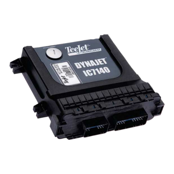
Figure 1-2: DynaJet IC7140 ECU Top and Bottom Views Software Updates As TeeJet Technologies continues to enhance its software, updates for the console will be made available at www.teejet.com.See DynaJet Software Update Instructions bulletin 98-01571 at the end of this chapter for details and instructions. -
Page 8: Ecu Orientation
DynaJet® IC7140 ECU Orientation The DynaJet IC7140 ECU needs to know which orientation it is Orthogonal Orientations mounted, or the system will not work properly. Note the direction of The DynaJet IC7140 ECU is to be mounted orthogonally on the the ECU label, connections, and left/right edges in relation to the vehicle. -
Page 9: Component Installation
DynaJet® IC7140 COMPONENT INSTALLATION DynaJet IC7140 installation includes eight (8) output driver options where each driver consists of eight (8) nozzle harnesses and is tailored to the customer’s specific equipment. The following is general installation information. Specific instructions will be based on selected components and will be tailored to the machine. -
Page 10: Component Installation Instructions
DynaJet® IC7140 Figure 1-4: DynaJet IC7140 Hybrid System Diagram Component Installation Instructions Power Source Power must be sourced from the battery using a (18) 60 amp fused battery cable [45-05943] which connects to a (17) 6 gauge power cable [45-05942- xx] to connect to the (16) Power Distribution Module [78-05121-xx]. -
Page 11: Pressure Sensor
DynaJet® IC7140 Pressure Sensor Without a Pressure Interface Pressure Sensor Cable [45-05887 or 45-05886] connects the DynaJet ECU Harness to the Pressure Sensor [16-05015]. Extension cables 404-0045 or 404-0039 are also available to connect the pressure sensor to the DynaJet Hybrid ECU Harness. (2-2) 18 Position Cinch Dust Cap to cover the open port on the DynaJet IC7140 ECU Module... -
Page 12: Software Update Instructions
SOFTWARE UPDATE DynaJet® IC7140 As TeeJet Technologies continues to enhance its software, updates for the console will be made available at www.teejet.com. You must have the software update folder stored on a USB storage device prior to beginning the update. - Page 13 To verify non-English languages have installed, change the console language. Please contact TeeJet Technologies with any questions or for assistance. TEEJET TECHNOLOGIES IS NOT RESPONSIBLE FOR DAMAGE DUE TO IMPROPER DOWNLOAD AND INSTALLATION OF AN UPDATE English-International www.teejet.com ©...
-
Page 14: Chapter 2 - Screen Introduction
DynaJet® IC7140 CHAPTER 2 - SCREEN INTRODUCTION Congratulations on the purchase of your new DynaJet IC7140 ECU built on the ISOBUS architecture. When used within the guidelines of this manual, the DynaJet IC7140 will be a reliable droplet size control system. BASIC SCREEN USE The DynaJet IC7140 display comprises Available ECU buttons, an interactive information display and softkeys. -
Page 15: How To Navigate Settings Options
DynaJet® IC7140 While DynaJet is in Disengage Mode, press to go to DynaJet IC7140 ECU. ► Interactive Information Display – Displays all system information, menus and operation interactions as well as may contain buttons for additional screen options or settings. ►... -
Page 16: Selecting A Numeric Value
DynaJet® IC7140 Selecting a Numeric Value Enter the numeric value using the slide bar or number pad then use the Accept button to save the value. Figure 2-4: Setting a Numeric Value Example Numeric Value Range Minimum Range Maximum Accept Zoom In Escape Zoom Out... -
Page 17: Chapter 3 - Initial Start-Up & Calibrations
DynaJet® IC7140 CHAPTER 3 - INITIAL START-UP & CALIBRATIONS The following is the steps required for first-time setup of the DynaJet IC7140 system. When these settings and calibrations are completed, operation should be possible. WARNING! With each nozzle change or when nozzles are replaced, a system calibration (steps NO. 5 CALIBRATE THE RATE CONTROLLER REGULATION and NO. -
Page 18: 2 Establish Select Settings 17
Pressure Sensor Max is codes require the console to be restarted. strongly suggested. Other machine settings and user parameters can Contact an authorized TeeJet Technologies local dealer for unlock be adjusted as needed after calibrating the system. code availability. -
Page 19: No Rate Controller Communications
DynaJet® IC7140 No Rate Controller Communications Setup and Select Nozzle Machine Setup is found in the Main Menu screen. When initially Preset nozzle favourites allows saving of up to five (5) nozzles for setting up the system, setting parameters for Number of Sections, quick recall. -
Page 20: No. 3 Get To Know The Control Modes
DynaJet® IC7140 NO. 3 GET TO KNOW THE CONTROL MODES To begin calibrating the system, an operation mode needs to be established. There are three types of Operation Modes: Manual Mode – Select the intended nozzle and the target PWM Duty Cycle Percentage. The system will calculate and display the droplet sizes for the nozzle selected. -
Page 21: No. 4 Preform System Functional Test
DynaJet® IC7140 NO. 4 PREFORM SYSTEM FUNCTIONAL TEST Prior to attempting to use the DynaJet IC7140, perform the following functional test of the system. Further details for fine-calibrating the system are in “Calibrate the DynaJet IC7140 System” section of this guide. Ensure Current Rate Control System is Operating Normally 1. -
Page 22: Flow Pulses Tests
DynaJet IC7140 System. Contact TeeJet Technologies Customer 3. Adjust the rate controller gain value until stable. Support or an authorised TeeJet Technologies dealer if additional support is required. Controller gain value at minimum pressure: Test 1B – Maximum Operating Pressure Determine controller gains values with operating pressure at MAXIMUM. -
Page 23: Test 2 - Duty Cycle 50
DynaJet® IC7140 Test 2 – Duty Cycle 50% Test 3 – Duty Cycle “Minimum Duty Cycle” 1. Start by setting DynaJet IC7140 duty cycle to Start by setting DynaJet IC7140 duty cycle set to “Minimum Duty Cycle” value (default is Test 2A –... -
Page 24: Select Gain Preset
DynaJet® IC7140 ◄ Gain Too High – getting close to the target droplet size will Select Gain Preset be slow and cause the system to oscillate extremely rapidly. Gain Preset Setup establishes up to five (5) presets of While the system is trying to settle on a target droplet size, proportional/derivative gain combinations. -
Page 25: Calibrating The System
DynaJet® IC7140 Highest Pressure/Smallest Droplet Size Calibrating the System The following steps will use the DynaJet IC7140’s Proportional Gain Calibrate Proportional Gain and Derivative Gain settings to calibrate the system: 1. On the Operation screen, using the DROPLET SIZE 1. Set Operation Mode to Adjustable Droplet Mode. ENGAGEMENT/ DISENGAGEMENT KEYS, choose the highest Adjustable Droplet Mode –... -
Page 26: Chapter 4 - Home Screen
DynaJet® IC7140 CHAPTER 4 - HOME SCREEN The Home screen gives access to the DynaJet IC7140’s available functions. NOTE: Information on the ECU will vary depending on the parameters set by the user and the OEM. Figure 4-1: Home Screen DynaJet IC7140 ECU Quick Overview Box Home Screen Options... -
Page 27: Accessing The Home Screen
DynaJet® IC7140 System Overview – Press to access the System Overview screen to locate any problems as well as give information on selected drivers or solenoids Disengage Mode – Press to activate Disengage Mode. Disengage Mode Not Available – Shown when Disengage Mode is not available due to an active application state such as Master Switch On or one or more sections on. -
Page 28: Errors
DynaJet® IC7140 Errors Disengage Mode Initialisation errors and lost communication appear on the Home While in Disengage mode, all DynaJet functions are locked off and screen to alert the operator of certain issues and prevent the console cannot be activated nor accessed. Rate controller functions may from entering operation mode until rectified. -
Page 29: Chapter 5 - Setup
DynaJet® IC7140 CHAPTER 5 - SETUP Set up the DynaJet through options in both the Main Setup Menu and Nozzle Favorites screen. TeeJet defaults and ranges are included on the User Settings Log included in the Appendix. Defaults and ranges established by an OEM may vary. Main Setup Menu The main setup menu accesses machine setup, gain Accessing the Main Setup Screen... -
Page 30: Main Settings Menu
DynaJet® IC7140 MAIN SETTINGS MENU NOTE: The menu structure on your display might vary from the one displayed in this User Manual depending on the UT being used and the OEM settings. This user manual will display all possible options. Figure 5-6: Main Setup Screen Overview Highlighted Menu Option Menu Options... -
Page 31: Machine Setup
DynaJet® IC7140 Machine Setup Figure 5-8: Machine Setup with Rate Controller Machine Setup is used to configure machine settings. When a rate controller is on the system with readable communications, some settings are controlled by the rate controller. WARNING! With each nozzle change or when nozzles are replaced, a system calibration (steps NO. -
Page 32: Gain Preset Setup
DynaJet® IC7140 Figure 5-9: Nozzles per Section Figure 5-11: Visual Over Maximum Individual Nozzles Gain Preset Setup Gain Preset Setup establishes up to five (5) presets of proportional/derivative gain combinations. WARNING! With each nozzle change or when nozzles are replaced, a system calibration (steps NO. - Page 33 DynaJet® IC7140 Gain Preset Number Derivative Gain Each one of up to five (5) gain presets can be selected to establish Used to settle larger errors by getting to the approximate target different sets of gain combinations. droplet size more quickly. For example, if a boom section is turned on, derivative gain then applies a one-time gain.
-
Page 34: User Interface
If Advanced Turn Figure 5-15: User Interface Compensation is unlocked, Standard Turn Compensation Unlock is not available. Contact an authorized TeeJet Technologies local dealer for unlock code availability. See bulletin 98-01563 Standard Turn Compensation Unlock for unlock instructions. -
Page 35: Oem Settings
DynaJet® IC7140 Turn Compensation Visual Figure 5-18: OEM Settings Enables/disables the turn compensation visual graph on the operation screens. Only available when Standard or Advanced Turn Compensation is unlocked. Figure 5-16: Turn Compensation Visual on Operation Screen Figure 5-17: Turn Compensation Visual Off OEM Settings OEM Settings are used to configure additional controller settings. -
Page 36: Help
DynaJet® IC7140 Help Figure 5-20: About The Help menu allows the operator to view system information, UT Diagnostics and Gyroscope Diagnostics; and enter the System Overview. 1. From the Main setup screen, select Help 2. Select from: ► About – provides information on the console and modules ►... -
Page 37: Ut Data Diagnostics
DynaJet® IC7140 UT Data Diagnostics Gyroscope Diagnostics Provides information regarding the universal terminal. Provides information regarding the gyroscope. • UT and ECU Address – the address the UT has acquired on the • Orientation − Horizontal, Label Up − Horizontal, Label Down •... -
Page 38: Nozzle Favourites
DynaJet® IC7140 NOZZLE FAVOURITES Figure 5-24: Nozzle Favourites Screen Add Nozzle Buttons Nozzle Presets Current Nozzle System Overview Options ► Nozzle Presets – Use to select one of the up to five (5) nozzles to be the current nozzle for determining droplet size information NOTE: When a rate controller is also on the system, the nozzle selected must match that which is selected on the rate controller. -
Page 39: Nozzle Presets
DynaJet® IC7140 Nozzle Presets Current Nozzle Selection Nozzle presets allow saving of up to five nozzles for quick recall. The The active nozzle for determining current droplet size information is selected current nozzle is used to determine droplet size information. the selected button. -
Page 40: Chapter 6 - Operation
DynaJet® IC7140 CHAPTER 6 - OPERATION The operation screen provides the user with important information and controls while operating the system. Information on the Operation screen will vary depending on the parameters set by the user and the OEM. Softkeys on the Operation screen give access to all the functions which are required during operation and will change with the Operation Mode selected. -
Page 41: Accessing The Operation Screen
DynaJet® IC7140 OPERATION MODES Accessing the Operation Screen The Operation screen can be accessed from the Home screen or from There are three types of Operation Modes: an error message. Manual Mode – Select the intended nozzle and the target 1. -
Page 42: Droplet Mode
DynaJet® IC7140 Droplet Mode Adjustable Droplet Mode Select the intended nozzle and the target droplet size range. The Select the intended nozzle and the droplet size range with the option system will calculate and display the median boom pressure required to adjust the target droplet size. -
Page 43: Boom Application Activity
DynaJet® IC7140 Adjusting Target Droplet Size More than 43 Nozzles Droplet Size Increase – Press to increase the When more than 43 nozzles are programmed, application status will target droplet size (decreases the target no longer include spacing between individual nozzles. pressure on the pressure gauge) Figure 6-11: Boom Application Activity - More than 43 Nozzles Droplet Size Decrease –... -
Page 44: Control Errors & Alerts
DynaJet® IC7140 CONTROL ERRORS & ALERTS NON-TOUCHSCREEN UT OPTIONS If there is an active control error, the value background will be will red When using a UT that does not have a touchscreen, screen options to indicate the error. The specific error will be specified on the pop-up will be available as additional softkeys not illustrated in the examples alert screen. -
Page 45: Turn Compensation
DynaJet® IC7140 TURN COMPENSATION Figure 6-17: Turn Compensation On – Straight As the vehicle turns, the PWM value of each nozzle is displayed on the screen as a graph to show how the system adjusts the PWM to compensate for the turn rate of the vehicle. NOTICE: Standard Turn Compensation or Advanced Turn Compensation must be unlocked to be available on the Operation screen. - Page 46 DynaJet® IC7140 Minimum PWM Maximum PWM Solution As minimum PWM is attained, it is represented with a flat spot on the If conditions allow, decrease speed, or disable a larger droplet size to Turn Compensation graph. Indicating implement speed is too slow, force a lower PWM.
-
Page 47: Chapter 7 - System Overview
DynaJet® IC7140 CHAPTER 7 - SYSTEM OVERVIEW Displays system graphically to help the operator locate any problems as well as give information on selected drivers or solenoids. NOTE: Information on the System Overview screen will vary depending on the parameters set by the user and the OEM. Figure 7-1: System Overview Screen Without Errors Pressure Interface Module Pressure Sensor... -
Page 48: Accessing The System Overview Screen
DynaJet® IC7140 Accessing the System Overview Screen DRIVER/SOLENOID INFORMATION The System Overview screen can be accessed from multiple locations including directly from the Home screen, through the Main Setup-> Specific information about each driver and its associated solenoids Help options or from an error message. can be accessed using the Previous Driver, Next Driver and Next Solenoid softkeys. -
Page 49: System Errors
DynaJet® IC7140 SYSTEM ERRORS Figure 7-7: Previous / Next Driver Errors with components of the system are displayed graphically on the System Overview screens to help the operator locate any problems. NOTE: Operation errors appear on the Operation screen. See the Operation chapter for details. -
Page 50: System Overview Screen
DynaJet® IC7140 System Overview Screen Home Screen Visibility The system overview screen will indicate the offending system The Home screen gives the user a quick overview of the status of the component in red with an error icon. The specific error will be system. -
Page 51: Appendix A - Dynajet Application Charts
DynaJet® IC7140 APPENDIX A – DYNAJET APPLICATION CHARTS DYNAJET IC7140 NOZZLE SELECTION Selection of the proper spray nozzle for use with the DynaJet IC7140 system is much like selecting the spray nozzle for a traditional spraying operation. Along with the extra application flexibility, DynaJet IC7140 brings a few other nozzle-related considerations that will be summarised below. 1. -
Page 52: Nozzle/Tip Selection Chart Explanation
DynaJet® IC7140 Nozzle/Tip Selection Chart Explanation These columns show droplet sizes for different styles of spray nozzle at These columns given pressures. Use these columns Just like a normal nozzle chart, these columns show speeds available at given rates. The show flow rates at to choose the best nozzle style for only difference is the range of values that corresponds to the range of flows available with... -
Page 53: Speed Range Available For Various Application Rates
DynaJet® IC7140 Speed Range Available for Various Application Rates Application Rates – Metric, 50 cm Nozzle Spacing Speed Range (km/h) 30% Minimum Duty Cycle Gauge 50 l/ha 75.0 l/ha 100 l/ha 125 l/ha 150 l/ha 175.0 l/ha 200 l/ha 250 l/ha 300 l/ha Tip Size Pressure... - Page 54 DynaJet® IC7140 Application Rates – US, 20" Nozzle Spacing 30% Minimum Duty Cycle Speed Range (MPH) Gauge 5 GPA 7.5 GPA 10 GPA 12 GPA 15 GPA 17.5 GPA 20 GPA 25 GPA 30 GPA Tip Size Pressure Pressure (PSI) (PSI) 11001 10.1...
- Page 55 DynaJet® IC7140 Application Rates – US Turf, 20" Nozzle Spacing 30% Minimum Duty Cycle Speed Range (MPH) Gauge 0.5 Gal/1000ft² 1.0 Gal/1000ft² 1.5 Gal/1000ft² 2.0 Gal/1000ft² 2.5 Gal/1000ft² 3.0 Gal/1000ft² 3.5 Gal/1000ft² 4.0 Gal/1000ft² 5.0 Gal/1000ft² Tip Size Pressure Pressure (PSI) (PSI) 11001...
- Page 56 DynaJet® IC7140 Application Rates – US Turf, 10" Nozzle Spacing 30% Minimum Duty Cycle Speed Range (MPH) Gauge 0.5 Gal/1000ft² 1.0 Gal/1000ft² 1.5 Gal/1000ft² 2.0 Gal/1000ft² 2.5 Gal/1000ft² 3.0 Gal/1000ft² 3.5 Gal/1000ft² 4.0 Gal/1000ft² 5.0 Gal/1000ft² Tip Size Pressure Pressure (PSI) (PSI) 11001...
-
Page 57: Appendix B - Troubleshooting Guide Unavailable Modes Operation Mode
DynaJet® IC7140 APPENDIX B – TROUBLESHOOTING GUIDE UNAVAILABLE MODES Operation Mode Disengage Mode Due to a system error, the Operation Mode is not available. Errors Disengage Mode is not available due to an active application state causing this unavailability include: such as Master Switch On or one or more sections on. -
Page 58: Turn Compensation Visual Unavailable
Turn Compensation is not available on the Operation screen. Turn screen is not shown. The Turn Compensation Visual can be Compensation is locked. Contact an authorized TeeJet Technologies enabled/disabled from the User Interface settings. Verify the Turn local dealer for unlock code availability. See bulletin 98-01563 Compensation Visual is enabled. - Page 59 DynaJet® IC7140 Alert Error Description Action Code 3008 Solenoid Current Too Low Solenoid current is below the low current limit. Go to SYSTEM OVERVIEW for details 3009 Missing Pressure Sensor Pressure sensor is not detected. Pressure sensor is required for Operation Mode. 3010 Missing Boom Interface Module Communication to the Boom Interface Module has been...
- Page 60 DynaJet® IC7140 Alert Error Description Action Code 3030 Operation Error: All Solenoids An issue on the system has occurred preventing access to Please stop application and address Closed the Operation screen. To avoid additional issues, all the operation issue Solenoids have been closed. 3031 Solenoid Not Working Properly At least one or more solenoids are not opening or closing...
- Page 61 DynaJet® IC7140 INITIALISATION BOOM SETUP ERROR WITH 8-OUTPUT DRIVERS When an 8-output driver system on start-up/initialisation has a missing solenoid in the 8 position of a driver, the number of sections on the DynaJet will not match the associated rate controller causing the 3028 Initialisation error due to the 3022 Boom Setup Error. This happens when using an 8-output driver and the solenoid in error happens to be sitting in the 8th position.
- Page 62 MAINTENANCE INSTRUCTIONS 115880 E-CHEMSAVER® MAINTENANCE INSTRUCTIONS System Flush The 115880 e-ChemSaver is a solenoid-actuated shutoff compatible with a wide range of TeeJet nozzle bodies equipped with a 1. Fill the product tank with at least 200 gallons / 750 liters of clean diaphragm check valve.
- Page 63 MAINTENANCE INSTRUCTIONS E-CHEMSAVER MAINTENANCE With proper equipment maintenance (as recommended by the equipment or chemical manufacturer), TeeJet solenoids are designed to provide up to 500 hours maintenance free operation. The following solenoid maintenance procedures should be performed on the solenoid or on individual nozzles if leaks are observed at a specific spray nozzle.
- Page 64 MAINTENANCE INSTRUCTIONS TEEJET TECHNOLOGIES Internal Inspection After any inspection, reassamble all the parts as shown in the Solenoid Disassembly and Reassembly instructions referred in this bulletin. Inspection Area Procedure Example Coil Assembly If any external body was present in Clean and Proper...
- Page 65 MAINTENANCE INSTRUCTIONS TEEJET TECHNOLOGIES Inspection Area Procedure Example Tube Sub-Assembly Before Clean and inspect the Tube Sub- Assembly (4). Replace the tube assembly if the rubber seal is worn or damaged. After Brown O-Ring Observe that the O-ring is well well- Proper O-Ring maintained.
- Page 66 MAINTENANCE INSTRUCTIONS SOLENOID DISASSEMBLY AND REASSEMBLY NOTE: O-rings (6, 8, 9) should be handled with care as they can be damaged/deformed. Disassembly 1. Loosen and remove the nylon Nut (1). 2. Separate the Coil Assembly from the rest of the Tube/Plunger Assembly (3-10).
- Page 67 MAINTENANCE INSTRUCTIONS TROUBLESHOOTING This is a list with the most common e-ChemSaver’s failures. NOZZLE LEAKING After setting off the spray, some nozzles are still leaking. Issue/Problem Solution Example Plunger’s gasket damaged Change the kit plunger-gasket (Reference AB115880-2-KIT). Sand Dust Blocking the Closure Solid particles present in the Remove any solid particle present.
- Page 68 MAINTENANCE INSTRUCTIONS TEEJET TECHNOLOGIES The e-ChemSaver Doesn’t Open During the spray, some nozzles remain closed not working. Probable causes and solutions. Issue/Problem Solution Example Blocked, dirty or stuck nozzle Clean the nozzle with water. Damaged electrical Change the coil (Reference connector CP115881-12).
- Page 69 Other Relevant Infomation Issue/Problem Solution Example Can I clean it with high It is possible. Try not to aim insisting pressure water? on the e-ChemSavers for too long time, particularly to the electrical connector. English-International www.teejet.com © TeeJet Technologies 2020 98-01580-EN-R0_A4LT-E-ChemSaver-MaintenanceInstructions-TB.docx...
- Page 70 USER SETTINGS LOG DynaJet® IC7140 Main Setup -> Machine Setup Description Factory Default Range/Options Suggested Setting Use Default ☐ Nozzle Spacing 50 cm / 20 in 1 - 2,000 cm / 1 - 787 in ☐ Pressure Sensor Maximum 10 bar / 145 psi 5.00 - 30.00 bar / 73 - 435 psi ☐...
- Page 71 USER SETTINGS LOG TEEJET TECHNOLOGIES Main Setup -> User Interface Description Factory Default Range/Options Suggested Setting Use Default • Off ☐ Use Preferred UT • On • Off Boom Section Beep ☐ • On • Off Turn Compensation Visual ☐...
- Page 72 • Pressure Based Regulation Base Pressure Based ☐ • Flow Based • All Open Solenoid Error State All Open ☐ • All Closed • All Open Solenoid Disengage State All Open ☐ • All Closed English-International www.teejet.com © TeeJet Technologies 2020 98-01557-EN-R1_A4LT-DynaJetIC7140-UserSettings.docx...
- Page 74 Flow rate (litre/minute or gallon/minute) determined by Duty Cycle For example: 50% (50% On & Off), turns a 05 nozzle to a 025 • 90% drift reduction with AIC11005 VP/VS or AITTJ6011004 VP • Optional: ISOBUS technology with turn compensation 98-05347-EN-R1_A4LT-DynaJetIC7140-UM.docx English-International www.teejet.com © TeeJet Technologies 2020...
Need help?
Do you have a question about the DYNAJET IC7 140 and is the answer not in the manual?
Questions and answers