Table of Contents
Advertisement
Quick Links
Advertisement
Table of Contents

Related Manuals for Mindman MFP01 Series

Summary of Contents for Mindman MFP01 Series
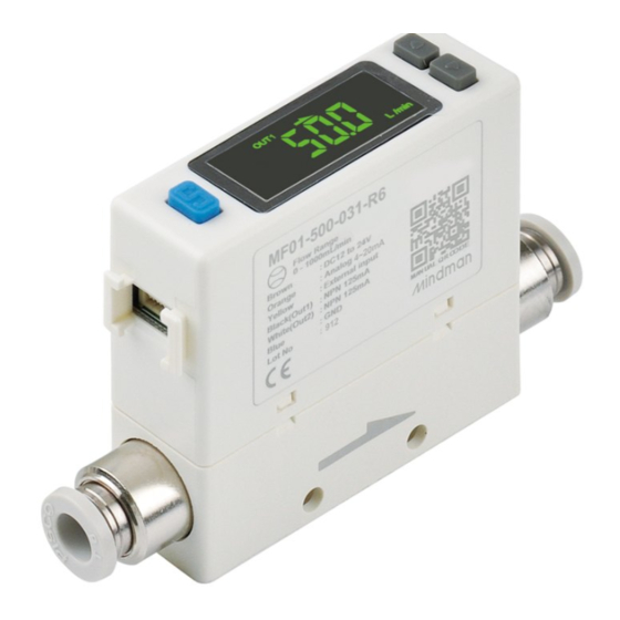
- Page 1 INSTRUCTION MANUAL Flow & Pressure Sensor MFP01 series 210107...
-
Page 2: Table Of Contents
MFP01 Contents FLOW & PRESSURE SENSOR ( INSTRUCTION MANUAL ) Product features ..................................1 Application ....................................3 Thermal mass flow sensor principles ......................... 5 Order example ..................................5 Specifications ...................................6 Output type ....................................7 Pressure loss characteristics .............................8 Installation instructions ..............................9 ● Piping ........................................9 ●... -
Page 3: Product Features
MFP01 Product features FLOW & PRESSURE SENSOR ( INSTRUCTION MANUAL ) Cost Control DRY AIR, N User-friendly RS-485 MODBUS High Performance CONTROL High Precision Flow Pressure Indicator accuracy ± 3% F.S. ± 2% F.S. Repeatability ± 1% F.S. ± 0.2% F.S. Cost Reduction Traditional 2 ×... - Page 4 MFP01 Product features FLOW & PRESSURE SENSOR ( INSTRUCTION MANUAL ) 2-in-1 Design Flow display Pressure and flow rate simultaneous monitoring Pressure display Accumulated flow rate display at a glance Accumulated flow rate display Multiple output function Digital display Switch output Analog output Accumulated pulse output Instantaneous flow value...
-
Page 5: Application
MFP01 Application FLOW & PRESSURE SENSOR ( INSTRUCTION MANUAL ) Application Paint and coating flow monitoring Air flow and pressure management of paint and coating processes. Application Laser welding monitoring Precision management of shielding gas, flow rate and pressure. - Page 6 MFP01 Application FLOW & PRESSURE SENSOR ( INSTRUCTION MANUAL ) Application Application Suction operation Electronic part installation Detect the suction state of micro- Control the tension of gold wire for electronic parts by flow rate. bonding electronic parts. Application Application Air consumption Leakage detect monitoring...
-
Page 7: Thermal Mass Flow Sensor Principles
MFP01 Thermal mass flow sensor principles / Order example FLOW & PRESSURE SENSOR ( INSTRUCTION MANUAL ) Thermal mass flwo sensor principles Symmetric Skewed Skewed temperature profile temperature profile temperature profile Temperature Temperature Temperature Temperature Temperature Temperature Sensor 1 Sensor 2 Sensor 1 Sensor 2 Sensor 1... -
Page 8: Specifications
MFP01 Specifications FLOW & PRESSURE SENSOR ( INSTRUCTION MANUAL ) Model Fluid Dry air, N , Non-corrosive / Non-flammable gas Measured flow rate range 0 ~ 500 mL/min 0 ~ 1000 mL/min 0 ~ 5 L/min 0 ~ 10 L/min 0 ~ 50 L/min 0 ~ 100 L/min 0 ~ 200 L/min... -
Page 9: Output Type
MFP01 Output type FLOW & PRESSURE SENSOR ( INSTRUCTION MANUAL ) Normal open mode Normal close mode Hysteresis mode Hysteresis mode FH-1(FH-2) FH-1(FH-2) H-1(H-2) H-1(H-2) FL-1(FL-2) FL-1(FL-2) L-1(L-2) L-1(L-2) Window comparator mode Window comparator mode FH-1(FH-2) FH-1(FH-2) H-1(H-2) H-1(H-2) FL-1(FL-2) FL-1(FL-2) L-1(L-2) L-1(L-2) -
Page 10: Pressure Loss Characteristics
MFP01 Pressure loss characteristics FLOW & PRESSURE SENSOR ( INSTRUCTION MANUAL ) MFP01 - 005 - MFP01 - 010 - 0.018 0.1 MPa 0.1 MPa 0.006 0.016 0.2 MPa 0.005 0.014 0.3 MPa 0.2 MPa 0.012 0.004 0.35 MPa 0.010 0.4 MPa 0.3/0.35/0.4 0.003... -
Page 11: Installation Instructions
MFP01 Installation instructions FLOW & PRESSURE SENSOR ( INSTRUCTION MANUAL ) Installation instructions ● Piping ● Mounting Bracket / Optional Parts Install the pipe by following the arrow indication that shows The LCD display may be difficult to see at certain angles. the air flow direction on the product. -
Page 12: Wiring Diagrams
MFP01 Wiring diagrams FLOW & PRESSURE SENSOR ( INSTRUCTION MANUAL ) ● Wiring diagrams NPN Output, Analog Output and External Input PNP Output, Analog Output and External Input ● NPN Output / Analog Voltage Output / External Input ● PNP Output / Analog Voltage Output / External Input Brown (Power supply +) Brown (Power supply +) 1kΩ... -
Page 13: Dimensions
MFP01 Dimensions FLOW & PRESSURE SENSOR ( INSTRUCTION MANUAL ) Port size R6 (ø6) R8 (ø8) Quick fitting ø6, ø8 2×ø2.5×5.5 depth Code A (mm) Tube I.D. ø8 92.2 ø6 Port size F1C (Rc1/8") F4C (Rc1/4") Internal Thread Rc1/4”, Rc1/8” 2×ø2.5×5.5 depth Code B (mm) -
Page 14: Mounting Accessories
MFP01 Mounting accessories FLOW & PRESSURE SENSOR ( INSTRUCTION MANUAL ) Mounting bracket MP-A26 Mounting screw 33.6 P type 3×6 2-ø3.5 4×3.5 Panel type Front protective lid + Panel adapter MP-C4 Panel cut dimensions 60.5±0.3 Panel thickness 1~4.5 4×R3 or less Panel adapter MP-B4 Panel adapter... -
Page 15: How To Use
MFP01 How to use – Names and functions of individual parts FLOW & PRESSURE SENSOR ( INSTRUCTION MANUAL ) How to use ● Names and Functions of Individual Parts Panel description Output 2 Indicator Flow Symbol Output 1 Indicator Analog Signal Indicator Analog Signal Indicator Output 1 Indicator Pressure symbol... -
Page 16: Internal Structure
MFP01 How to use – Internal structure FLOW & PRESSURE SENSOR ( INSTRUCTION MANUAL ) Port size R6 (ø6) R8 (ø8) Port size F1C (Rc1/8") F4C (Rc1/4") Part name (Material) Part name (Material) Case (PC + ABS) Resin Body (PBT) Electronic circuit board O-ring (Viton) Sensor (SiC) -
Page 17: Functions Instructions
MFP01 How to use – Functions instructions FLOW & PRESSURE SENSOR ( INSTRUCTION MANUAL ) Function setting mode Function Item Default setting Explanation code oUt1 oUt1 OUT1 setting oUt1 FLoy OUT1 sensor correspondence FLoy OUT1 output mode oUt1 OUT1 output type Select output 1 corresponding to 50 % of maximum measured flow rate flow sensor or pressure sensor. -
Page 18: Measurement Mode
MFP01 How to use – Functions instructions FLOW & PRESSURE SENSOR ( INSTRUCTION MANUAL ) Function Item Default setting Explanation code Select the flow value is shown rEFE rEFE Flow reference standard selection F-07 under standard (ANR) or normal rEFE Flow reference standard selection condition ( NOR ). -
Page 19: Operation Setting Instructions
MFP01 How to use – Operation setting instructions FLOW & PRESSURE SENSOR ( INSTRUCTION MANUAL ) ● Operation setting instructions At Measurement Mode, press button for more than 3 sec. to display [F-01]. Press button to select other setting Press button functions. - Page 20 MFP01 How to use – Operation setting instructions FLOW & PRESSURE SENSOR ( INSTRUCTION MANUAL ) ● [ ] OUT1 setting selection F-01 Setting corresponding sensor and operating mode of OUT1. Pressure sensor setting Press button at Function Setting Mode to display [ F-01 ] [ oUt1 ].
-
Page 21: [F-02] Out2 Setting Selection
MFP01 How to use – Operation setting instructions FLOW & PRESSURE SENSOR ( INSTRUCTION MANUAL ) ● [ ] OUT2 setting selection ● [ ] Response time selection F-02 F-04 Setting corresponding sensor and operating mode of OUT2. Select proper response time to avoid switch output chattering. Flow sensor setting <... -
Page 22: [F-05] Display Refresh Time Selection
MFP01 How to use – Operation setting instructions FLOW & PRESSURE SENSOR ( INSTRUCTION MANUAL ) ● [ ] Response time selection ● [ ] Display refresh time selection F-04 F-05 Select proper response time to avoid switch output chattering. Select the proper display refresh time to reduce frequently changing value. -
Page 23: [F-06] Unit Selection
MFP01 How to use – Operation setting instructions FLOW & PRESSURE SENSOR ( INSTRUCTION MANUAL ) ● [ ] Display refresh time selection ● [ ] Unit selection F-05 F-06 Select the proper display refresh time to reduce frequently Select the flow unit and pressure unit of the sensor. changing value. -
Page 24: [F-07] Flow Reference Standard Selection
MFP01 How to use – Operation setting instructions FLOW & PRESSURE SENSOR ( INSTRUCTION MANUAL ) ● [ ] Flow reference standard selection ● [ ] Accumulated value hold selection F-07 F-09 Select the flow value is shown under standard or normal The default setting is "OFF", the accumulated flow value is condition. -
Page 25: [F-10] Flow Sensor Display Mode Selection
MFP01 How to use – Operation setting instructions FLOW & PRESSURE SENSOR ( INSTRUCTION MANUAL ) ● [ ] Flow sensor display mode selection ● [ ] External input selection F-10 F-92 Select to display Instantaneous Flow or Accumulated Flow Accumulated flow external reset: The accumulated flow Mode. -
Page 26: [F-93] Modbus Rtu Setting
MFP01 How to use – Operation setting instructions FLOW & PRESSURE SENSOR ( INSTRUCTION MANUAL ) ● [ ] MODBUS RTU Setting F-93 MODBUS transmission protocol can be set according to user requirements. Press button at Function Selection Mode to display [ F-93 ] [ AbUS ]. -
Page 27: [F-94] Fine Adjustment Setting
MFP01 How to use – Operation setting instructions FLOW & PRESSURE SENSOR ( INSTRUCTION MANUAL ) ● [ ] Fine adjustment setting ● [ ] Fine adjustment setting F-94 F-94 This function is to fine adjust flow and pressure display values. This function is to fine adjust flow and pressure display values. -
Page 28: [F-95] Forced Output Function
MFP01 How to use – Operation setting instructions FLOW & PRESSURE SENSOR ( INSTRUCTION MANUAL ) ● Pressure zero adjustment function ● [ ] Forced output function F-95 The displayed value can be adjusted to "0" when the pressure To turn the analog ON/OFF forcibly. is within ±3% of the zero point at the time of shipment from the factory. -
Page 29: Reset Accumulated Flow Function
MFP01 How to use – Operation setting instructions FLOW & PRESSURE SENSOR ( INSTRUCTION MANUAL ) ● Reset accumulated flow function ● Bottom value display Accumulate flow value return to zero. The minimum pressure and instantaneous flow, from when the power was supplied to this moment, is detected and updated. -
Page 30: Modbus Rtu Instruction
MFP01 Modbus RTU instruction FLOW & PRESSURE SENSOR ( INSTRUCTION MANUAL ) Error code Explanation Operation Error code Explanation Operation ID Number ( 0 ~ 255 ) Read / Flow display refresh time 0000H Range : 0 ~ 255 Write 0 : 200 ms Read / 000DH... - Page 31 MFP01 Modbus RTU instruction FLOW & PRESSURE SENSOR ( INSTRUCTION MANUAL ) Error code Explanation Operation Error code Explanation Operation Read / OUT1 output mode Flow setting value ADH2 0029H Write FLOW PRESSURE Fixed hysteresis setting for flow Read / Read / 0018H 0 : HYS...
-
Page 32: Error Code Instruction
MFP01 Error code instructions FLOW & PRESSURE SENSOR ( INSTRUCTION MANUAL ) Error Type Error Code Error Condition Troubleshooting OUT1 Output 1 load current is more L/min excess load than 125 mA. current error 2. 0 0 Turn power off and check the cause of L/min overload current or lower the current load under 125 mA, then restart. -
Page 33: Caution For Safety
Caution for safety FLOW & PRESSURE SENSOR ( INSTRUCTION MANUAL ) This section indicate the levels of risks with the labels of Danger, Warning and Caution. Danger indicates high level of risk, will lead to fatal or serious injuries if not avoided. DANGER WARNING Warning indicates medium level of risk, it might cause death or serious injuries. - Page 34 Other Precautions the responsible of Mindman. After power is supplied, the output will remain off until the Our warranty applies solely to our product, not to any ther display is turned on.
Need help?
Do you have a question about the MFP01 Series and is the answer not in the manual?
Questions and answers