Table of Contents
Advertisement
Quick Links
Advertisement
Table of Contents

Related Manuals for Vaisala AP10


Summary of Contents for Vaisala AP10
- Page 1 M211860EN-E User Guide Vaisala VaiNet Wireless Access Point AP10...
- Page 2 This product contains software developed disclosed to a third party without prior by Vaisala or third parties. Use of the written permission of the copyright holder. software is governed by license terms and Translated documents and translated...
-
Page 3: Table Of Contents
Time synchronization..................11 Network security....................11 Power supply.....................11 Remote management..................12 ESD protection....................13 Installation......................14 AP10 installation location and range............14 3.1.1 Mounting in Plenum Space..............14 Setting up AP10....................15 Mounting AP10....................18 Touchscreen interface................20 Accessing the touchscreen interface............20 Overview of touchscreen interface.............. - Page 4 AP10 User Guide M211860EN-E Technical support.................... 43 Warranty......................43 Recycling......................43...
- Page 5 Figure 2 Front........................8 Figure 3 Connector panel....................8 Figure 4 Rear........................9 Figure 5 AP10 remote management using viewLinc Enterprise Server.... 12 Figure 6 AP10 properties in viewLinc................13 Figure 7 AP10 mounting methods................18 Figure 8 AP10 screw mounting dimensions.............. 19 Figure 9 Touch interface home screen..............
- Page 6 AP10 User Guide M211860EN-E List of tables Table 1 Document versions (English)................5 Table 2 Related manuals....................5 Table 3 AP10 power supply specifications..............11 Table 4 Troubleshooting table..................35 Table 5 Wireless........................ 38 Table 6 General........................38 Table 7 Operating environment..................39 Table 8 Inputs and outputs....................
-
Page 7: About This Document
AP10 technical specification (page 38) M211860EN-D April 2020 Updated technical data chapter. Regulatory compliance statements are now provided in a separate document AP10 and RFL100 Regulatory Compliances (M212235EN). M211860EN-C February 2019 Updated regulatory compliance information and sections Overview of web interface (page 24) -
Page 8: Documentation Conventions
Lists tools needed to perform the task. Indicates that you need to take some notes during the task. 1.4 Trademarks Vaisalaâ is a registered trademark of Vaisala Oyj. The LoRa ™ name and associated logo are trademarks of Semtech Corporation or its subsidiaries. -
Page 9: Product Overview
AP10 can be powered from the Ethernet connector using Power over Ethernet (PoE) or from the power supply connector using the included AC/DC adapter. If both power sources are connected, the AC/DC adapter is utilized to power the device. AP10 is IP22 rated, and is suitable for indoor industrial applications. -
Page 10: Ap10 Parts
(10 ... 30 VDC) Service port (micro-USB) USB port for hardware expansion (USB type A) Reset button. Push to restart, push and hold to revert AP10 to factory settings. RJ-45 Ethernet port. Can be powered by Power over Ethernet (PoE). -
Page 11: Vainet Devices In Viewlinc Monitoring System
Housing screws (do not remove) 2.3 VaiNet devices in viewLinc Monitoring System VaiNet access points create links between Ethernet and Vaisala devices using the VaiNet protocol. Wireless device registration is handled by viewLinc Enterprise Server. Whenever a new data logger is added to the system, it is automatically identified by an access point, which forwards the data logger’s information to the server. -
Page 12: Data Transfer In A Vainet Network
AP10 User Guide M211860EN-E VaiNet wireless devices are not limited to using a single access point. If multiple access points are available, VaiNet devices can switch access points to maintain their connection to the viewLinc Monitoring System. The strength of the wireless signal is used to determine the optimum network data path. -
Page 13: Time Synchronization
AP10 has a supercapacitor as a backup power source for its realtime clock. If AP10 is left without power for more than a day, the realtime clock will lose its time. If this happens AP10 will have to synchronize its clock with the NTP servers before it can operate its radio. This is typically the case when an AP10 is installed - it needs to synchronize its clock before it can start to connect VaiNet data loggers. -
Page 14: Remote Management
• Approved for use in your country 2.7 Remote management AP10 has a web interface for remote management. Additionally, some settings can be remotely managed using viewLinc Enterprise Server software. Remote management operations can be performed directly from the Sites Manager > Hosts and Devices tree. -
Page 15: Esd Protection
Figure 6 AP10 properties in viewLinc Select Sites Manager > Show hosts to see the IP addresses of all connected hosts. Select the IP address of any AP10 to open its web interface in your browser. 2.8 ESD protection Electrostatic discharge (ESD) can cause immediate or latent damage to electronic circuits. -
Page 16: Installation
3.1 AP10 installation location and range In a typical indoor space, the wireless range of AP10 is at least 100 m (328 ft). In an open space with line-of-sight and no interfering structures, the range can be over 500 m (1640 ft). Up to 8 access points can be placed within range of each other, even side-by-side, as long as they each have their own VaiNet channel. -
Page 17: Setting Up Ap10
• It is usually easiest to configure the access point before mounting it. 1. Connect the Ethernet cable to Ethernet port of AP10. If possible, connect to the same network where the viewLinc Enterprise Server is, so that you can verify the connection... - Page 18 The power supply comes with multiple adapters for wall sockets. Connect the adapter you need, and plug in the power supply to a wall socket. 3. A setup wizard starts when AP10 is first powered up. Use the touch interface to complete the wizard: a.
- Page 19 NTP servers requires Internet access, and network firewall must allow the access point to connect to UDP port 123. An NTP connection error continues to be shown while AP10 is synchronizing time with the listed NTP servers. It may take up to 15 minutes...
-
Page 20: Mounting Ap10
AP10 User Guide M211860EN-E 3.3 Mounting AP10 • AP10 Access Point, set up and configured • Content of AP10 delivery package • Crosshead screwdriver (if screw mounting is used) Figure 7 AP10 mounting methods Mounting with cable ties (2 pcs) Mounting with screws (4 pcs) -
Page 21: Figure 8 Ap10 Screw Mounting Dimensions
3. Connect the Ethernet cable. 4. If the Ethernet cable does not provide power, connect the DC power supply: a. Connect the plug to the power supply connector of AP10. Make sure the plug is oriented correctly and goes in all the way. -
Page 22: Touchscreen Interface
M211860EN-E 4. Touchscreen interface 4.1 Accessing the touchscreen interface The display on AP10 is a capacitive touchscreen. The touchscreen interface may be locked by a password. 1. Touch the screen to start using the interface. Do not wear gloves when using the touchscreen. -
Page 23: Figure 10 Touch Interface Data Logger Information Screen
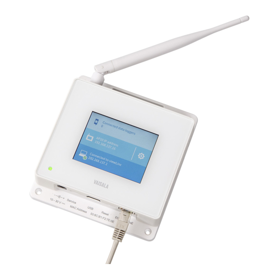
Chapter 4 – Touchscreen interface • Middle: access point IP address and status. Touch the symbol to open the Settings screen. • Bottom: status of viewLinc Enterprise Server connection. Connected data loggers Figure 10 Touch interface data logger information screen Data logger information screen shows connection and battery level status of each data logger that is connected to this access point. -
Page 24: Figure 11 Touch Interface Settings Menu
AP10 User Guide M211860EN-E Settings Settings screen provides local access to most of the access point's settings. Some advanced functions, such as firmware update, are only available using the web interface. Figure 11 Touch interface settings menu... -
Page 25: Web Interface
1. Verify the IP address of the access point from the touchscreen interface. 2. Open a web browser. 3. In the address field of the web browser, enter https:// and the IP address of AP10. For example: https://192.168.10.47 4. The default user interface language is English. If you want to use another language for this session, select it from the drop-down menu. -
Page 26: Overview Of Web Interface
AP10 User Guide M211860EN-E 5.2 Overview of web interface System summary System Summary page lists the identifying information and current operating settings of the access point. Some information, such as the hardware ID of the device, is only available on this page. -
Page 27: Figure 13 Web Interface Data Loggers Page
Chapter 5 – Web interface Data loggers Data Loggers page lists each data logger that is connected to this access point. You can see the latest measurement values, battery level, and the signal quality of the VaiNet connection to the data logger. Last connection is the amount of time since last successful contact with the data logger. -
Page 28: Figure 14 Web Interface Network Settings
AP10 User Guide M211860EN-E Settings pages Figure 14 Web interface network settings Figure 15 Web interface DNS, NTP, and VaiNet settings page... -
Page 29: Figure 16 Web Interface Viewlinc Settings Page
Chapter 5 – Web interface Figure 16 Web interface viewLinc settings page Figure 17 Web interface installation mode settings page... -
Page 30: Figure 18 Web Interface Security Settings Page
AP10 User Guide M211860EN-E Figure 18 Web interface security settings page Vaisala recommends changing the default password. Minimum password length is 8 characters. Allowed characters are 0–9 and a–z. Figure 19 Web interface display and LED settings page... -
Page 31: Figure 20 Web Interface Backup And Restore Page
Chapter 5 – Web interface AP10 maintenance Figure 20 Web interface backup and restore page You can back up and restore your current configuration settings on the Back up and Restore page. This is convenient for testing settings, and copying the same settings to several access points. -
Page 32: Figure 21 Web Interface Firmware Update Page
AP10 User Guide M211860EN-E Figure 21 Web interface firmware update page For firmware update procedure, see Updating AP10 firmware (page 32). Figure 22 Web interface restart and reset page... -
Page 33: Figure 23 Web Interface Support Page
Figure 23 Web interface support page If Vaisala support requests a diagnostic data package from your AP10, you can retrieve it from the Support page. Starting from firmware version 2.0.0, this page also has a switch for disabling Vaisala remote access connections to this access point. -
Page 34: Maintenance
6. Maintenance 6.1 Cleaning AP10 • Lint-free cloth • Isopropyl alcohol (70 %) Do not spray anything directly on the AP10. 1. Moisten some lint-free cloth with isopropyl alcohol (70 %). 2. Wipe the access point and its antenna. 6.2 Updating AP10 firmware •... -
Page 35: Figure 24 Firmware Update Page In Web Interface
Accessing the web interface (page 23). b. Select AP10 Maintenance > Restart and Reset > Restart > Restart. 3. Wait for the restart to complete and log in again to the web interface. 4. Select AP10 Maintenance > Firmware Update. - Page 36 If you have already tried twice, continue to the next step. 3. Select AP10 Maintenance > Back up and Restore > Back up to back up your settings to a file. 4. Revert the AP10 back to factory settings; see...
-
Page 37: Troubleshooting
LEDs on the Ethernet connector are flashing. Contact your local IT support. The following message is AP10 has just started up and it Wait for AP10 to synchronize shown on the display: has lost accurate time during time with the NTP (Network power off. -
Page 38: Verifying Operation Of Ap10
1. Connect the Ethernet cable. 2. If the Ethernet cable does not provide power, connect the DC power supply: a. Connect the plug to the power supply connector of AP10. Make sure the plug is oriented correctly and goes in all the way. -
Page 39: Performing A Factory Reset
They will automatically rejoin the system, but their connection to viewLinc Enterprise Server will be temporarily interrupted. 1. If the AP10 is not on, power it up using the DC power supply and wait for it to complete the startup. -
Page 40: Technical Data
AP10 User Guide M211860EN-E 8. Technical data 8.1 AP10 technical specification Table 5 Wireless Property Specification Networking standards Vaisala VaiNet Modulation LoRa ™ chirp spread spectrum modulation Output power 13 dBm (20 mW) Antenna Non-removable external antenna Typical range (indoors) At least 100 m (328 ft) -
Page 41: Table 7 Operating Environment
Chapter 8 – Technical data Property Specification User interfaces Web browser interface Local touchscreen interface User interface languages English, German, French, Portuguese, Spanish, Swedish, Chinese, Japanese Internal clock Synchronizes with Network Time Protocol (NTP) server. NTP server connection required for operation. -
Page 42: Ap10 Accessories And Spare Parts
311 × 133 × 37 mm (12.24 × 5.24 × 1.46 in) Materials Housing PC/ABS blend Display window Chemically strengthened glass Antenna 8.2 AP10 accessories and spare parts Table 10 Spare parts Item Item code Power supply for AP10 244784SP Mounting kit... -
Page 43: Ap10 Dimensions
Chapter 8 – Technical data 8.3 AP10 dimensions Ø3.50 [0.11] 116 [4.57] 133 [5.24] 37 [1.46] [in] Figure 25 AP10 access point dimensions... -
Page 45: Maintenance And Calibration Services
Maintenance and calibration services Vaisala offers comprehensive customer care throughout the life cycle of our measurement instruments and systems. Our factory services are provided worldwide with fast deliveries. For more information, see www.vaisala.com/ calibration. • Vaisala Online Store at store.vaisala.com is available for most countries. - Page 48 www. v aisala.com...
Need help?
Do you have a question about the AP10 and is the answer not in the manual?
Questions and answers