Download Print this page
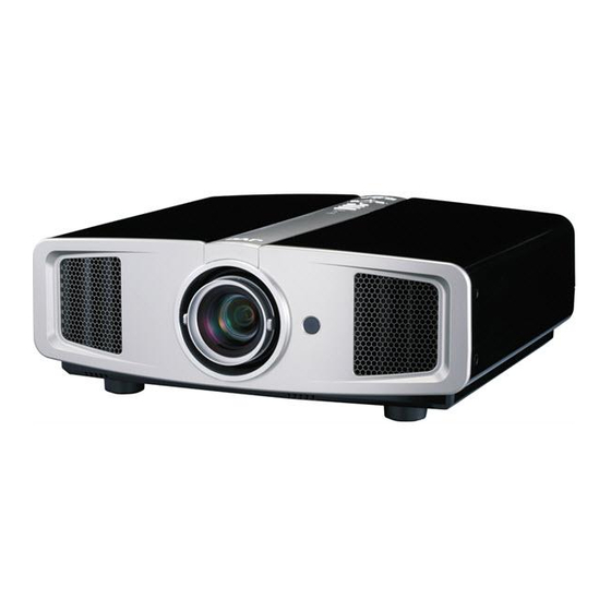
JVC D-ILA DLA-HD1-BC Service Manual

JVC D-ILA DLA-HD1-BC Service Manual

Home theater

Advertisement

SERVICE MANUAL
D-ILA HOME THEATER PROJECTOR
3 S ERVICE MANUAL
PA023
2007
........
........
OFF
OPERATE
ON
HDMI 1
HDMI 2
COMP.
VIDEO
S-VIDEO
ASPECT
CINEMA
NATURAL
DYNAMIC
C
N
D
USER
USER
USER
1
2
3
COLOR
SHARP
GAMMA
+
+
COLOR
SHARP
COLOR
-
-
TEMP
CONTRAST
BRIGHT
INFO
HIDE
MENU
EXIT
ENTER
TEST
LIGHT
PROJECTOR
COPYRIGHT © 2007 Victor Company of Japan, Limited
1
PRECAUTION. . . . . . . . . . . . . . . . . . . . . . . . . . . . . . . . . . . . . . . . . . . . . . . . . . . . . . . . . . . . . . . . . . . . . . . . . 1-3
2
SPECIFIC SERVICE INSTRUCTIONS . . . . . . . . . . . . . . . . . . . . . . . . . . . . . . . . . . . . . . . . . . . . . . . . . . . . . . 1-7
3
DISASSEMBLY . . . . . . . . . . . . . . . . . . . . . . . . . . . . . . . . . . . . . . . . . . . . . . . . . . . . . . . . . . . . . . . . . . . . . . 1-15
4
ADJUSTMENT . . . . . . . . . . . . . . . . . . . . . . . . . . . . . . . . . . . . . . . . . . . . . . . . . . . . . . . . . . . . . . . . . . . . . . . 1-19
5
TROUBLESHOOTING . . . . . . . . . . . . . . . . . . . . . . . . . . . . . . . . . . . . . . . . . . . . . . . . . . . . . . . . . . . . . . . . . 1-22
DLA-HD1-BC,
DLA-HD1-BE,
DLA-HD1-BU

TABLE OF CONTENTS

COPYRIGHT © 2007 Victor Company of Japan, Limited
R
No.PA023
2007/3

Advertisement

loading

Summary of Contents for JVC D-ILA DLA-HD1-BC

  • Page 1: Table Of Contents

    SERVICE MANUAL D-ILA HOME THEATER PROJECTOR PA023 2007 3 S ERVICE MANUAL DLA-HD1-BC, DLA-HD1-BE, DLA-HD1-BU ....OPERATE HDMI 1 HDMI 2 COMP. VIDEO S-VIDEO ASPECT CINEMA NATURAL DYNAMIC USER USER USER COLOR SHARP GAMMA COLOR SHARP COLOR TEMP CONTRAST BRIGHT INFO HIDE...
  • Page 2 SPECIFICATION GENERAL ELECTRIC Type D-ILA HOME THEATER PROJECTOR Color system NTSC, NTSC4.43, PAL, PAL-M, PAL- N, SECAM (Auto/Manual switch) Approx. 435 mm × 172.5 mm × 418.5 mm Dimensions (W × H ×D) (Approx. 17-7/8" × 6-7/8" × 16-1/2") Analog video input for- 480i, 480p, 576i, 576p, 720p/50 Hz, 720p/60 Hz, 1080i/50 Hz, 1080i/60 Hz (Excluding handle, lens and protrusions)
  • Page 3: Precaution

    SECTION 1 PRECAUTION SAFTY PRECAUTIONS Prior to shipment from the factory, JVC products are strictly in- Consequently, when servicing these products, replace the spected to conform with the recognized product safety and elec- cathode ray tubes and other parts with only the specified trical codes of the countries in which they are to be parts.
  • Page 4 1.1.2 Safety Check after Servicing Examine the area surrounding the repaired location for damage (4) Leakage current test or deterioration. Observe that screws, parts and wires have been Confirm specified or lower leakage current between earth returned to original positions, Afterwards, perform the following ground/power cord plug prongs and externally exposed ac- tests and confirm the specified values in order to verify compli- cessible parts (RF terminals, antenna terminals, video and...
  • Page 5 Do not block the ventilation holes as this may cause the internal temperature to rise and possibly result fire. When the inside of the unit requires cleaning, consult your nearest JVC dealer or service center. High voltage Bottom chassis Turn off before opening this lamp cover.
  • Page 6 INSTALLATIONS 1.2.1 Installation method The D-ILA system (reflecting type active matrix liquid crystal system) does not require convergence adjustment. Note the following when placed on a floor (refer to OPERATING INSTRUCTIONS for actual operating method). (1) Place the projector at the position needed for the required image size observe the projector is not tilted horizontally. [The image size is 60 to 200(wide side) inches diagonal (16:9), requiring a projection distance of 1.78m to 6.08m] (2) Adjust the placement site and screen tilt so that the projection angle is perpendicular to the screen.
  • Page 7: Specific Service Instructions

    JVC's newly developed optical engine uses an inorganic reflective polarizing plate made from a glass substrate on the surface of which are aluminium ribs with a width of a 20~30 nanometers, aligned with a pitch of 120~130 nanometers.
  • Page 8 2.3.2 Operation button & LED location TOP SIDE Light on (Red): Warning mode Light on (Red): Standb y mode Light on (Green): During projection Light on/Blinking (Orange): Lamp warning Blinking (Green): Image is temporarily hidden Blinking (Red): Cool Down mode To turn on/off the power To hide the image temporarily To switch input...
  • Page 9 LAMP UNIT INSTRUCTIONS Refer to the OPERATING INSTRUCTIONS for a detailed oper- ating description. 2.4.1 Lamp life Life of the projector lamp is about 2000 hours. ∗ Lamp use time can be checked at the menu < Information > - [Lamp time].
  • Page 10 PROJECTION SPECIFICATIONS AND NOTES 2.5.1 Projection distance 2.5.3 Other cautions • The usable projection distance (focus obtainable) is tele side : • Use care not to directly touch the lens. Clear soiling from the approx. 3.63m to 12.23m / wide side : approx. , 1.78m to lens with optical lens paper or a photographer's blower.
  • Page 11 SERVICE MENU The service menu contains items not ordinarily needed by the us- 2.7.3 Basic operation er. Use these as necessary during service. Use the following buttons to operate the service menu. (1) Choose the SETTING MENU with the [ / ] button. 2.7.1 Enter (2) When the [ ] button is pressed after choosing the SET- (1) No menu shown.
  • Page 12 2.7.4 Setting items Item Adjustment range Initial value Function Model Only the display Display of model name Main Only the display Display of Main CPU software version Only the display Display of Sub CPU software version Only the display Display of DD program version Only the display Display of OSD program version Color Temp.
  • Page 13 FACTORY SHIPPING SETTING Item Adjustment range Initial value Function Image Adjust Contrast -30 - 30 Adjusts the contrast of the projected image. Brightness -30 - 30 Adjusts the brightness of the projected image. Color -30 - 30 Adjusts the color density of the projected image. Tint -30 - 30 Adjusts the hue of the projected image.
  • Page 14 Item Adjustment range Initial value Function Flip V On/Off Select this when the projector is hung from the ceiling. High Altitude Mode On/Off Select this when using the projector in a location of low atmo- spheric pressure (higher than 900 meters above sea level). Back Color Blue/Black Blue...
  • Page 15: Disassembly

    SECTION 3 DISASSEMBLY CAUTION: • Make sure that the AC plug is disconnected from the wall outlet. • The illuminating lamp remains very hot even after the unit has been turned off. Allow sufficient time until the lamp is cooled off for safety work.
  • Page 16 TOP CABINET OPERATION PWB CONTROL (BOTTOM) DUCT EXT(COVER) TEMP PWB EARTH PLATE LAMP COVER LAMP UNIT IR PWB FRONT COVER BLIND INTAKE FRONT PANEL LENS CAP Fig.3-1 1-16 (No.PA023)
  • Page 17 REMOVING THE DUCT EXT(TOP) AND OPTICAL 3.11 REMOVING THE I/F PWB AND PROCESSOR PWB BLOCK ASSY (Fig.3-2) (Fig.3-2) • Remove the LAMP UNIT. • Remove the LAMP UNIT. • Remove the TOP CABINET. • Remove the TOP CABINET. • Remove the FRONT PANEL. •...
  • Page 18 DUCT EXT(TOP) BALLAST CASE REAR CHASSIS LAMP FAN HOLDER LAMP FAN INSULATOR SHEET DUCT TOP VIEW FRONT LAMP FAN LAMP BALLAST BRACKET UNIT EARTH SPPRING FAN PWB DUCT EXT(BOTTOM) DUCT(PS FAN) LAMP BLIND BRACKET DUCT INTAKE FAN DUCT PS FAN DUCT FAN HOLDER INTAKE(DEV)
  • Page 19: Adjustment

    SECTION 4 ADJUSTMENT BEFORE STARTING ADJUSTMENT (1) Adjustment items utilize a personal computer. (5) Use care not to disturb internal controls and parts not spe- (2) Data back up is required before adjustments. cifically mentioned. (3) Allow the equipment and test instruments adequate time (6) Unless specifically mentioned in the "ADJUSTMENT"...
  • Page 20 ADJUSTMENT PROCEDURE 4.4.1 LAMP TIME BACKUP Instruments Lamp Time Software REPLACING COMPONENTS PROCESSOR PWB Test point Adjustment menu Preparation Note : Perform this operation during standby mode. ADJUSTMENT (1) Run HD1_LAMP_Copy.exe and start HD1_LAMP_Copy. (2) From the COM Port, select the PC COM number being used.
  • Page 21 4.4.3 PIXEL SHIFT Instruments REPLACING COMPONENTS OPTICAL BLOCK Test point Service menu <Adjust> → <Pixel shift> Adjustment menu Preparation ADJUSTMENT (1) From Service menu, select the adjustment pattern of the color cross-hatch. (2) From the Service menu, set <Adjust>to <Pixel Shift>. (3) Adjust [H Pixel Adj.R], [H Pixel Adj.G], [H Pixel Adj.B] to make H direction (Pixel Shift) to become the best point.
  • Page 22: Troubleshooting

    SECTION 5 TROUBLESHOOTING PROTECTIVE SENSOR AND PROTECTIVE SWITCH In event of abnormal operation due to circuit or component failure, setting error or other reason, in order to prevent serious damage to the set and preserve the integrity of peripheral equipment, sensors and switches are provided for protective functions. Cooling is conducted at the same time a corresponding LED flashes (about 90 seconds).
  • Page 23 5.2.2 Mearsures during abnormality In event of the following be sure to disconnect the power cord from the AC outlet, and reset the projector mode. Error code 01 Lamp dose not light Check the DC voltage of POWER PWB and input LAMP BALLAST UNIT voltage defective Check the LAMP ON signal...
  • Page 24 Error code 11 SUB CPU operation faulty PROCESSOR PWB defective Error code 16,17,18 DD circuit operating faulty POWER PWB and input Check the DC input voltage of DD PWB voltage defective and PROCESSOR PWB Check the communication line betweeen DD PWB defective DD PWB and PROCESSOR PWB DD PWB or PROCESSOR PWB defective 1-24 (No.PA023)
  • Page 25 Error code 08,09 Internal/out side temperature abnormally high Ambient temperature of the unit should be mode into Check ambient temperature specification within the limits. Clean the filter of the unit and stopped up of filter TEMP PWBor THERMO Check the DC voltage of Check the quantity of wind of SWITCH defective cooling fan...
  • Page 26 Error code 07 Cooling fan stopped Reinstall connectors Check the connector installation of FAN PWB Fan lock detect circuit of FAN Check the fan stop signal of PWB defective cooling fan Cooling fan defective Check the DC input voltage of coolin fan FAN PWB defective 1-26 (No.PA023)
  • Page 27 ERROR LOG (SELF-DIAGONOSIS RECORD AND INDICATION) 5.3.1 Outline By using the special setting and adjustment software, data related to abnormal operation (history) stored in the projector can be load. On the basis of contents "LED (INDICATOR) WARNING INDICATONS" set and lamp use time, internal and external temperature, and other data prior to the previous usage time can be viewed as a table.
  • Page 28 Victor company of Japan, Limited ILA CENTER 12, 3-chome, Moriya-cho, Kanagawa-ku, Yokohama-city, Kanagawa-prefecture, 221-8528, Japan (No.PA023) Printed in Japan...

This manual is also suitable for:

D-ila dla-hd1-beD-ila dla-hd1-bu