Table of Contents
Advertisement
Quick Links
Advertisement
Table of Contents

Related Manuals for REV Robotics REV-31-1595


Summary of Contents for REV Robotics REV-31-1595
- Page 1 CONTROL HUB USER'S MANUAL Control Hub Guide © REV Robotics, LLC 2020...
-
Page 2: Table Of Contents
Logic Level Converter ..............................29 Connnecting a 5V Motor Encoder ..........................30 Connecting a 5V Sensor .............................. 30 Sensor Compatability Chart ............................31 DIMENSIONS ..................................34 IMU Location ................................35 WiFi Radio Antenna ..............................35 Control Hub Guide © REV Robotics, LLC 2020... -
Page 3: Overview
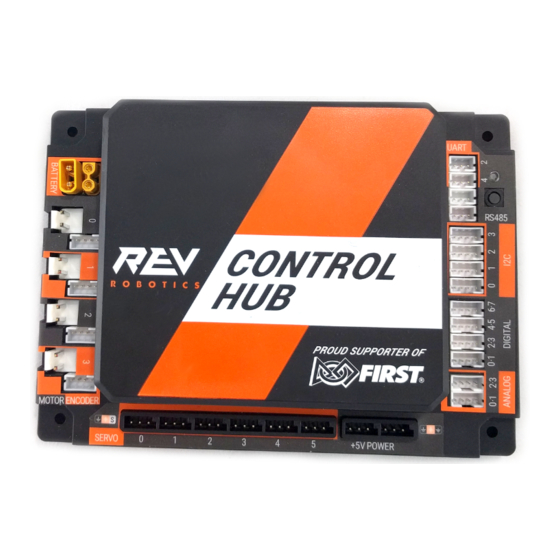
1 OVERVIEW 1.1 Control Hub Basics The REV Robotics Control Hub is an affordable all in one educational robotics controller that provides the interfaces required for building robots, as well as other mechatronics, with multiple programming language options. The Control Hub was designed and built as an easy to use, dependable, and durable device for use in classroom and the competition. -
Page 4: Port Pin Outs
1.2 Port Pin Outs Control Hub Guide © REV Robotics, LLC 2020... -
Page 5: Protection Features
Expansion Hub, from a single battery source. Most teams will want to use premade cables which can be sourced from the REV Robotics website directly (Table 1) for convenience, but teams can also make their own cables. These connectors are solder cup style and do not require any crimping tools;... -
Page 6: Jst Vh - Motor Power
Figure 1: How to Use a JST VH Cable REV Robotics recommends in most cases that teams use pre-made cables because the quality of the crimp is better when made using industrial tooling. These cables can be bought directly from the REV Robotics Website (Table 2) or through other online vendors. -
Page 7: Jst Ph - Sensors And Rs485
Figure 2: How to Use a JST PH Cable REV Robotics recommends in most cases that teams use pre-made cables because the quality of the crimp is better when made using industrial tooling. These cables can be bought directly from the REV Robotics Website (Table 4 and Table 5) or through other online vendors. - Page 8 Header, JST PH, 4-pin, Side Entry S4B-PH-K-S 455-1721-ND Housing, JST PH, 3-pin PHR-3 455-1126-ND Header, JST PH, 3-pin, Top Entry B3B-PH-K-S 455-1705-ND Header, JST PH, 3-pin, Side Entry S3B-PH-K-S 455-1720-ND Connector Datasheet: http://www.jst-mfg.com/product/pdf/eng/ePH.pdf Control Hub Guide © REV Robotics, LLC 2020...
-
Page 9: Quick Start
* Other FTC legal part numbers exist. Optional Additional Materials needed to Connect an Expansion Hub: • Expansion Hub (REV-31-1153) • XT30 Extension Cable (REV-31-1392) • JST PH 3-pin Communication Cable (REV-31-1417) Control Hub Guide © REV Robotics, LLC 2020... -
Page 10: System Wiring Diagram
2. The Control Hub is ready to pair with the Driver Station when the LED turns green. Note: the light blinks blue every ~5 seconds to indicate that the Control Hub is healthy. Control Hub Guide © REV Robotics, LLC 2020... - Page 11 3. Power on your Android Device by holding down the power button. 4. Open the Driver Station application from the HOME Screen. Control Hub Guide © REV Robotics, LLC 2020...
- Page 12 5. On the Driver Station page, open the menu from the top right corner, then select “Settings”. 6. Select, “Pairing Method” Control Hub Guide © REV Robotics, LLC 2020...
- Page 13 7. Select, “Control Hub” 8. Select, “Pair with Robot Controller”. Control Hub Guide © REV Robotics, LLC 2020...
- Page 14 9. Select “Wifi Settings” 10. Select the name of the Wifi network generated by your Control Hub. The SSID name starts with either “FIRST-“ or “FTC-“. Control Hub Guide © REV Robotics, LLC 2020...
- Page 15 12. After a couple of seconds, the Driver Station page will indicate the network name, a ping time, and battery voltage. Your Driver Station is now paired with your Control Hub! Control Hub Guide © REV Robotics, LLC 2020...
-
Page 16: Robot Configuration
The Robot Configuration will allow you to give your sensors and actuators meaningful names that you can reference while programming. For this example, we will configure a simple two motor robot drivetrain (Figure 4). Figure 4: The miniBot is a Simple 2-Motor Robot Control Hub Guide © REV Robotics, LLC 2020... - Page 17 Select the menu on either the Driver Station or Robot Controller. Then select “Configure Robot”. Select “New” in the top left hand corner. Select “Expansion Hub Portal 1” (embedded). Select “Expansion Hub 1”. Control Hub Guide © REV Robotics, LLC 2020...
- Page 18 Always use descriptive names so that you can remember what a device does when you are programming. Repeat the process for “Port 1” and name the motor “right_drive”. Control Hub Guide © REV Robotics, LLC 2020...
- Page 19 I2C Bus 0. Add the built-in REV Expansion Hub IMU. Name it “imu” Press the “Done” button (at the top left corner of the page) 3 times. Press “Save”. Control Hub Guide © REV Robotics, LLC 2020...
-
Page 20: Adding An Additional Expansion Hub
(1) Expansion Hub to their robot. the 2020-2021 season. Read the official FTC Game Read the official FIRST Global manual for complete Manuals for complete game rules. game rules. Control Hub Guide © REV Robotics, LLC 2020... - Page 21 2. Use a 3-pin JST PH cable to connect the RS485 port on the Control Hub to the Expansion Hub. 3. From the Driver Station choose “Configure Robot” 4. Select “New” in the top left hand corner. Control Hub Guide © REV Robotics, LLC 2020...
- Page 22 Control Hub. “Expansion Hub 2” is the connected Expansion Hub. Configure and program as necessary. Please see the “Configure your robot” section of this document for an overview of configuration. Control Hub Guide © REV Robotics, LLC 2020...
-
Page 23: Switching Wifi Channels
The Control Hub can utilize either the 2.4 GHz or 5 GHz WiFi band. By default the Control Hub is set to a channel on the 2.4 GHz band. REV Robotics advises that during competition teams utilize a 5 GHz channel for robot communication. - Page 24 4. Select a 5 GHz channel noted in the () next to the channel number. Then select the “Change Channel” button next to the drop down. 5. At the main screen, confirm the channel is changed under “Network”. Control Hub Guide © REV Robotics, LLC 2020...
-
Page 25: Updating Control Hub Operating System
Using a web browser and a PC, follow the steps below for updating the Operating System on the Control Hub. Updating Control Hub OS Download the latest version of the Operating System from the REV Robotics website (www.revrobotics.com/software) 1. Power on the Control Hub, by plugging the 12V Slim Battery into the XT30 connector labeled “BATTERY”... - Page 26 Step 1 and press the “Update & Reboot” button. 7. Keep the Control Hub powered while the upload finishes. 8. Keep the Control Hub powered while the update is installed. The Control Hub will reboot to complete the update. Control Hub Guide © REV Robotics, LLC 2020...
-
Page 27: Wifi Reset
Robot Controller application installed on the Control Hub. Factory Reset Procedure 1. Press and hold the button on the front of the Control Hub. 2. While pressing the button, power on the Control Hub. Control Hub Guide © REV Robotics, LLC 2020... -
Page 28: Led Blink Codes
Expansion Hub is running on USB power only. This fault will clear when battery voltage is raised above Blinking Orange Anytime This will not be overwritten by the keepalive timeout pattern. Control Hub Guide © REV Robotics, LLC 2020... -
Page 29: Integrated Sensors
The REV Robotics Logic Level Converter is a PCB which generates a 5V output from the 3.3V input and uses a MOSFET on each signal line to create a bidirectional communication appropriate for a variety of digital signals include I2C communication (Figure 5). -
Page 30: Connnecting A 5V Motor Encoder
Control Hub (Figure 6). Figure 6: Connecting a Motor with 5V Encoder to a Control Hub Note: All REV Robotics Motors work directly with the Control Hub and Expansion Hub. 4.3 Connecting a 5V Sensor A variety of 5v sensors are usable with the Control Hub when used with a Logic Level Converter. -
Page 31: Sensor Compatability Chart
AdaFruit Color Sensor 45-2018 Modern Robotics Compass 45-2003 Modern Robotics Integrating Gyro 45-2005 Modern Robotics IR Locator 360 45-2009 Modern Robotics IR Seeker V3 45-2017 Modern Robotics Ranger Sensor 45-2008 Modern Robotics Control Hub Guide © REV Robotics, LLC 2020... - Page 32 Standard Motor Kit Quad 50-0001 Encoder MATRIX Max Motor Shaft Encoder Quad W38000 Encoder Tetrix Limit Switch No Adapter Needed 45-2401 Digital Custom Wiring Harness Required. See Section 4.5 for Details Modern Robotics Control Hub Guide © REV Robotics, LLC 2020...
- Page 33 Modern Robotics Touch Sensor No Adapter Needed 45-2007 Analog Custom Wiring Harness Required Modern Robotics Light Sensor 45-2015 Analog Not Officially Supported Modern Robotics Magnetic Sensor 45-2020 Analog Not Officially Supported Modern Robotics Control Hub Guide © REV Robotics, LLC 2020...
-
Page 34: Dimensions
5 DIMENSIONS Control Hub Guide © REV Robotics, LLC 2020... -
Page 35: Imu Location
When using the Control Hub please note the location of the WiFi Radio Antenna in the graphic below. Do not place a battery or thick metal plate above the Control Hub as it will interfere with the WiFi Radio signal. Control Hub Guide © REV Robotics, LLC 2020...
Need help?
Do you have a question about the REV-31-1595 and is the answer not in the manual?
Questions and answers