Table of Contents
Advertisement
Contents
1
1.1
1.2
1.3
1.4
1.5
1.6
1.6.1
1.6.2
2
2.1
3
3.1
3.3.1
3.3.2
3.3.3
3.3.4
3.3.5
3.4.1
3.4.2
3.4.3
3.5.1
3.5.2
3.5.3
3.5.4
4
4.1
SafeRoute®-System
Mini, Basic und Standard
System manual
WN 059722 45532 - 2019-03
EN
2
4.1.1
2
4.1.2
2
2
2
4.2.1
2
2
5
2
5.1
2
5.1.1
3
3
5.1.1.1
3
5.1.2
3
3
5.1.2.1
3
3
3
3
6
3
6.1
3
7
4
4
7.1
4
4
8
4
8.1
4
4
4
4
4
4
9
5
10
11
5
12
5
5
5
5
5
5
5
5
6
6
6
6
7
7
7
8
8
11
11
11
11
11
11
12
12
12
13
Advertisement
Table of Contents

Subscribe to Our Youtube Channel
Related Manuals for Dormakaba SafeRoute

Summary of Contents for Dormakaba SafeRoute
-
Page 1: Table Of Contents
Documents storage 4.2.1 DCW® bus addressing (door entry Abbreviations system) Symbols used Commissioning 1.6.1 Hazard categories Put the SafeRoute® system into operation 1.6.2 More symbols 5.1.1 SCU-UP and SCU-TL as SafeRoute® Safety Control Unit Intended use 5.1.1.1 Configure an SCU-UP/SCU-TL 2.2 General safety instructions... -
Page 2: About This Document
This document contains the information and SafeRoute® Control Unit - Control instructions for the installation and operation of unit of a SafeRoute® system in three a SafeRoute® system on an emergency exit door versions: unit according to EltVTR (12/1997 version) and DIN SCU-xx •... -
Page 3: Safety
Personnel qualification 3.3.1 SafeRoute® Control Unit Mounting, commissioning, testing and maintenance of the SafeRoute® system may only be performed by The SCU with the inserted license card is the persons authorized by dormakaba. SafeRoute® system’s control unit. The license card defines the SafeRoute®... -
Page 4: Electrical Door Lock Stv Xxx
Up to four different as well as • Release via emergency button (with alarm trigger) identical door locks can be connected to a SafeRoute® • Release in case of power failure system via the DCW® bus. All dormakaba STV xxx •... -
Page 5: Mounting
SCU 4 (Adr. 4) STV 4 (Adr.4) The SLI license card and the battery (from Standard license) are plugged into the SafeRoute® Control Unit. Fig. 2 Assignment of the LED segments in the illuminated The further mounting and connection of the ring SafeRoute®... -
Page 6: Scu-Dr As Saferoute® Control Unit (From Basic License)
Out 3 Out 4 (from Basic license) With TMS Soft® and the SafeRoute® configuration software, the functions of the components and the SafeRoute® system can be adapted. For more CPU1 information, see the TMS Soft® handbook. CPU2 The settings made with the SafeRoute® configuration software must be entered in the respective door unit’s... -
Page 7: Status Query Of A Configured Unit
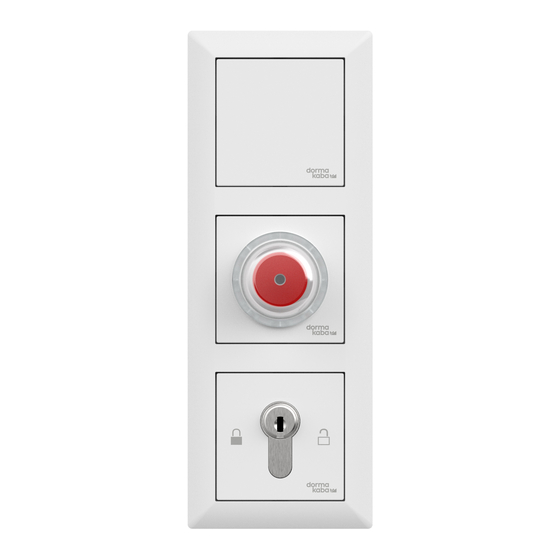
‣ The SCU switches to the operating state and initialization steps on the SafeRoute® Control Unit the illuminated ring lights up red permanently. emergency button’s illuminated ring. → The door is locked. -
Page 8: Troubleshooting
(mechanically). Here: Locks 1 and 2 are locked, lock 3 2. Turn the key switch to the right. is not. 3. Push the key switch to the left. → The door locks. SafeRoute® System WN 059722 45532 2019-03... - Page 9 System manual Troubleshooting Signal Cause Procedure The alarm system reports an alarm Reset to fire detector or smoke Alarm system has triggered via fire switch. detector or smoke switch or there is ‣ The alarm is automatically* an open circuit/short circuit to fire acknowledged.
- Page 10 The power supply does not meet the cable is too high, select a larger requirements or specifications. cable cross-section or place an additional power supply. *Depending on the parameterization, manual acknowledgment may also be required. SafeRoute® System WN 059722 45532 2019-03...
-
Page 11: Replacement And Removal Of Components
STV xxx or SCU control units, the replacement must be documented in the door unit’s inspection 4. Take over the replaced component’s DCW® log. The SafeRoute® system must then also be re- address (DIP switch). commissioned. 5. Reconnect the wiring to the component. -
Page 12: Maintenance
Disassembly is carried out in the reverse order of technicians authorized by dormakaba. mounting and must be carried out by qualified Customer service personnel. dormakaba Service can be reached at the toll-free The product must be disposed of in an number. environmentally friendly manner. Electro- E-mail: service@dormakaba.com... -
Page 13: Annex
System manual Annex Annex Mini Basic Standard Release ○ ○ ○ Via emergency button (with alarm trigger) Unlock Via key switch(without alarm trigger) – Temporary unlocking ○ ○ ● – Long-term unlocking ● – Permanent unlocking ○ ○ ○... - Page 14 System manual Maintenance SafeRoute® System WN 059722 45532 2019-03...
- Page 15 System manual Maintenance SafeRoute® System WN 059722 45532 2019-03...
- Page 16 Deutschland GmbH DORMA Platz 1 58256 Ennepetal Germany T: +49 2333 793-0 www.dormakaba.com F: +49 2333 793-4950...
Need help?
Do you have a question about the SafeRoute and is the answer not in the manual?
Questions and answers