
Related Manuals for ThermoForma 3110 Series


Summary of Contents for ThermoForma 3110 Series
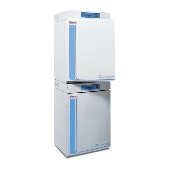
- Page 1 sales@artisantg.com artisantg.com (217) 352-9330 | Visit our website - Click HERE...
- Page 2 Model: 3110 Series* Water Jacketed Incubator Series II Operating and Maintenance Manual Manual No: 7033110 Rev. 9 *Refer to listing of all models on Page i. Artisan Technology Group - Quality Instrumentation ... Guaranteed | (888) 88-SOURCE | www.artisantg.com...
- Page 3 Model 3110/3210 Series ___________________________________________________________________________ Read This Instruction Manual. Single Chamber Models Model Sensor* Voltage** Failure to read, understand and follow the instructions in 3110 this manual may result in damage to the unit, injury to operat- ing personnel, and poor equipment performance. 3111 3120 3121...
- Page 4 Model 3110/3210 Series ___________________________________________________________________________ Important operating and/or maintenance instructions. Read the accompanying text carefully. Ce symbole attire l'attention de l'utilisateur sur des instructions importantes de fonctionnement et/ou d'entretien. Il peut être utilisé seul ou avec d'autres symboles de sécurité. Lire attentivement le texte d'accompagnement. Wichtige Betriebs- und/oder Wartungshinweise.
- Page 5 Model 3110/3210 Series ___________________________________________________________________________ Artisan Technology Group - Quality Instrumentation ... Guaranteed | (888) 88-SOURCE | www.artisantg.com...
-
Page 6: Table Of Contents
Model 3110/3210 Series ____________________________________________________________Table of Contents Table of Contents q. Enabling O Alarms to Trip Contacts ..3 - 3 r. Enabling Temp/RH to be Displayed ...3 - 4 s. -
Page 7: Section 1 - Installation And Start-Up
Model 3110/3210 Series ________________________________________________________Installation and Start-Up Section 1 - Installation and Start-up 1.1 Name and Description of Parts Control Panel Fill Port Power Switch Chamber Gas Jacket Vent Sample Port Heated Glass Inner Door Leveling Legs (4) Jacket Hose Drain Barb (remove plug Insert... -
Page 8: Control Panel Keys, Displays And Indicators
1.3 Operating the Control Panel Cal: Calibrate Menu Config: Configuration Menu The Model 3110 Series water jacket incuba- F Up and Down Arrows: Increases or decreases the parame- tor has four basic modes, which allow incubator ter values that are numbers, toggles the parameter values setup. -
Page 9: Displays
Model 3110/3210 Series ________________________________________________________Installation and Start-Up The chart below shows the selections under each of the modes. SETPOINT CALIBRATION CONFIGURATION Default Mode Temperature Temp Offset Audible Overtemp CO2 Cal New HEPA timer IR CO2 Span Replace HEPA reminder O2 Cal at 20.7% Access Code O2 Offset Temp Lo Alarm... -
Page 10: Installing The Unit
Model 3110/3210 Series ________________________________________________________Installation and Start-Up 1.5 Installing the Unit a. Choosing the Location 1. Locate the unit on a firm, level surface capable of sup- porting the unit’s operational weight of 365 lbs. (166kg). 2. Locate away from doors and windows and heating and air conditioning ducts. -
Page 11: Preliminary Cleaning And Disinfecting
Model 3110/3210 Series ________________________________________________________Installation and Start-Up Back of top Incubator d. Installing the Access Port Filter Stacking brackets Locate the opening in the top left corner of the interior chamber. Remove the tape from the opening on the outside of Insert 1/4-20 bolts the unit. -
Page 12: Installing The Shelves
Model 3110/3210 Series ________________________________________________________Installation and Start-Up g. Installing the Shelves h. Leveling the Unit Check the unit for being level by placing a bubble-style level on one of the shelves. Turn the hex nut on the leveler counterclockwise to lengthen the leg, or clockwise to shorten it. Level the unit front-to-back and left-to-right. -
Page 13: Filling The Humidity Pan
“Dry-outs” will have an adverse effect on the humidity cleared. Refer to Section 4.1, Table of Alarms. level. Note: Model 3110 Series Water Jacketed Incubator is shipped Exit for from the factory with a rust inhibitor added to the water inside... -
Page 14: Connecting The N Gas Supply
Model 3110/3210 Series ________________________________________________________Installation and Start-Up This incubator is designed to be operated with CO gas only. Connecting a flammable or toxic gas can result in a haz- ardous condition. Gases other than CO should not be connected to this equipment. CO gas cylinders have UN1013 labeled on the cylinder and are equipped with a CGA 320 outlet valve. -
Page 15: Setting The Overtemp Setpoint
Model 3110/3210 Series ________________________________________________________Installation and Start-Up b. Setting the Overtemp Setpoint c. Setting the CO Setpoint All T/C CO cells are precalibrated at the factory at 37°C, high humidity, and 10% CO . Therefore, if a temperature set- The independent overtemp circuit is designed as a point of 37°C has been entered, the humidity pan filled, and the safety to protect the incubator only. - Page 16 Model 3110/3210 Series ________________________________________________________Installation and Start-Up Chart 1-1 Set Mode Press MODE to light SET Config Heat Temp 36.9 Enter Mode SET POINTS Silence Inject % CO Scroll for Parameters To Set: Numbers increase Press MODE to move Operating Press Enter to CALIBRATE Enter Mode...
-
Page 17: Section 2 - Calibration
Model 3110/3210 Series ___________________________________________________________________Calibration Section 2 - Calibration b. Calibrating Thermal Conductivity CO System Models 3110, 3111, 3130 and 3131 have a thermal conduc- tivity (T/C) CO sensor. Thermal conductivity of the incubator 2.1 Calibration Mode atmosphere is not only effected by the quantity of CO present, but also by the air temperature and the water vapor present in After the unit has stabilized, several different systems can... -
Page 18: Calibrating The O System
Model 3110/3210 Series ___________________________________________________________________Calibration All models equipped with an IR/CO sensor have an auto- Calibration at 20.7% matic calibration that occurs every 24 hours, and lasts for 5 to 6 1. Press the Mode key until the CAL indicator lights. minutes. -
Page 19: Calibrating Relative Humidity
Model 3110/3210 Series ___________________________________________________________________Calibration e. Calibrating Relative Humidity All 3110 Series incubators can be equipped with an option- al direct readout relative humidity sensor. This is a readout only of the chamber relative humidity. It does not provide any con- trol of the relative humidity in the cabinet. - Page 20 Model 3110/3210 Series ___________________________________________________________________Calibration 2 - 4 Artisan Technology Group - Quality Instrumentation ... Guaranteed | (888) 88-SOURCE | www.artisantg.com...
-
Page 21: Section 3 - Configuration
Model 3110/3210 Series _________________________________________________________________Configuration Section 3 - Configuration 1. Press the Mode key until the Config indicator lights. 2. Press the right arrow until REPL HEPA XX is displayed. 3. Press the up/down arrow to choose the number of 3.1 Configuration Mode months desired. -
Page 22: Setting High Temp Alarm Limit (Tracking Alarm)
Model 3110/3210 Series _________________________________________________________________Configuration f. Setting High Temp Alarm Limit (tracking alarm) i. Setting High CO Alarm Limit (tracking alarm) The high temp alarm limit is the deviation from the tem- The high CO alarm limit is the deviation from the CO set- perature setpoint that will cause a high temp alarm. -
Page 23: Setting New Span Number For T/C Co
Model 3110/3210 Series _________________________________________________________________Configuration l. Setting New Span Number for T/C CO2 Sensors o. Setting a Low O Alarm Limit (tracking alarm) If a new T/C CO sensor is being installed, the two num- On models with a O control system, O alarms may be bers on the factory installed sticker on the T/C cell must be configured. -
Page 24: Enabling Temp/Rh To Be Displayed
Model 3110/3210 Series _________________________________________________________________Configuration r. Enabling Temp/RH to be Displayed 1. Press the Mode key until the Config indicator lights. 2. Press the right arrow until Tnk Sel X is displayed in the On units that are equipped with the RH option, the upper message center. - Page 25 Model 3110/3210 Series _________________________________________________________________Configuration 3 - 5 Artisan Technology Group - Quality Instrumentation ... Guaranteed | (888) 88-SOURCE | www.artisantg.com...
- Page 26 Model 3110/3210 Series _________________________________________________________________Configuration 3 - 6 Artisan Technology Group - Quality Instrumentation ... Guaranteed | (888) 88-SOURCE | www.artisantg.com...
- Page 27 Model 3110/3210 Series _________________________________________________________________Configuration 3 - 7 Artisan Technology Group - Quality Instrumentation ... Guaranteed | (888) 88-SOURCE | www.artisantg.com...
- Page 28 Model 3110/3210 Series _________________________________________________________________Configuration 3 - 8 Artisan Technology Group - Quality Instrumentation ... Guaranteed | (888) 88-SOURCE | www.artisantg.com...
-
Page 29: Section 4 - Alarms
4.1 Alarms The Model 3110 Series incubator alarm system is shown in the table below. When an alarm is active, the message appears in the LED message center. Pressing Silence disables the audible alarm for the ringback period. However, the visual alarm continues until the incubator returns to a normal condition. -
Page 30: O2 Snsr Err (Alarm)
Model 3110/3210 Series ______________________________________________________________________Alarms When multiple alarm conditions occur, active messages are c. CO2 SNSR ERR displayed in the message center one at a time, updating at 5 second intervals. Pressing Silence during multiple alarms caus- If the cables or connectors between the main microproces- es all active alarms to be silenced and to ring back in 15 min- sor board and the CO sensor, or between the CO... - Page 31 Do not use powdered gloves for tissue cultures. Millcreek Road, Box 649 • Marietta, Ohio 45750 USA • 740-373-4763 USA and Canada 888-213-1790 • Telefax: 740-373-4189 • http://www.service@thermoforma.com Artisan Technology Group - Quality Instrumentation ... Guaranteed | (888) 88-SOURCE | www.artisantg.com...
- Page 32 Incubators ______________________________________________________________________________ Preventive Maintenance Preventive Maintenance for Water Jacket Incubators Refer to Manual Action Daily Weekly Monthly 3 to 6 Yearly 2 years Section Months Check CO tank levels. Inspect door latch, hinges and door gasket seal. 1.5j Check water level in the humidity pan, ½” from top * Verify and document CO , humidity and temperature calibration, as applicable...
-
Page 33: Section 5: Routine Maintenance
Model 3110/3210 Series __________________________________________________________________Maintenance Section 5: Routine Maintenance 3. Remove the filter from the air sample filter tubing. Carefully pull down and remove the HEPA filter. 4. Remove the wingnuts securing the top duct to the interi- Before using any cleaning or decontamination or. -
Page 34: Cleaning The Cabinet Exterior
Model 3110/3210 Series __________________________________________________________________Maintenance 5.2 Cleaning the Cabinet Exterior 13. Install the top duct by feeding the temperature sensors, air sample tubing (and RH sensor, if applicable) through Clean the incubator exterior with a damp sponge or soft, the appropriate holes in the duct as it is raised to the top well-wrung cloth and mild detergent dissolved in water. -
Page 35: Replacing Fuses
Model 3110/3210 Series __________________________________________________________________Maintenance Refer to item “D” in the illustration and the drawing in Figure 5-5. The heater wiring connector is of yellow 17. Install the lower inner door hinge, identified as location rubber which should be visible when the strain relief is “L”... - Page 36 Model 3110/3210 Series __________________________________________________________________Maintenance 5 - 4 Artisan Technology Group - Quality Instrumentation ... Guaranteed | (888) 88-SOURCE | www.artisantg.com...
- Page 37 Model 3110/3210 Series __________________________________________________________________Maintenance 5 - 5 Artisan Technology Group - Quality Instrumentation ... Guaranteed | (888) 88-SOURCE | www.artisantg.com...
-
Page 38: Hepa Filter Maintenance
Model 3110/3210 Series __________________________________________________________________Maintenance Figure 5-8, Electronics Drawer 1. When the fuse has been replaced, slide the electronics There are three fuses in the incubator that can be replaced. drawer back in, being very careful to place the door To replace a fuse: heater cable back into the provided slot so that the draw- 1. -
Page 39: Replacing The Air Sample Filter
Model 3110/3210 Series __________________________________________________________________Maintenance 5. After water jacket has finished draining, remove the hose 5.7 Replacing the Air Sample Filter barb insert and secure on the front Press to release of the unit. See Figure 5-10 and 5- The air sample filter should be replaced whenever the HEPA filter is replaced. -
Page 40: Adding Or Replenishing The W/J Rust Inhibitor
5.12 Adding or Replenishing the Rust Inhibitor The Model 3110 Series incubators are shipped from the factory with a rust inhibitor added to the water in the jacket. This inhibitor must be replenished every 2 years. Mix 1 bag/bottle of the rust inhibitor with a gallon of water in the resistance range from 50K to 1M Ohm/cm. -
Page 41: Section 6 - Factory Installed Options
Model 3110/3210 Series _______________________________________________________________Factory Options Section 6 - Factory Installed Options to additional 1535 black to additional 1535 6.1 Connections to External Equipment modules modules a. Connecting the Remote Alarm Contacts (2) orange wires (1) red wire (1) green wire CAUTION (3) yellow wires (1) black wire... -
Page 42: Gas Guard For Co Or N
N (190640/190642) power cord from the wall outlet. The 3110 Series incubators can be equipped with a built-in 2. Open the exterior cabinet door and remove the two gas guard system that will operate with either a CO or a N screws shown in Figure 6-4. -
Page 43: Activating The Built-In Gas Guard
Figure 6-9 (or N ) Inlet #2 Tank. The 3110 Series incubators can be equipped with a In addition, the incubator automatically changes the Tank humidity sensor to monitor the relative humidity (RH) inside Sel in Configure mode from 1 to 2 to indicate that the incubator the chamber. -
Page 44: Accuracy Of The Humidity Readout
Model 3110/3210 Series _______________________________________________________________Factory Options The following table lists some typical RH levels at differ- As determined in carefully controlled laboratory tests, the ent O and CO percentages. smaller the difference between the temperature of the bath and the setpoint temperature of the incubator, the better the unifor- mity. -
Page 45: Section 7 - Specifications
Model 3110/3210 Series ________________________________________________________________Specifications Section 7 - Specifications *Specifications are based on nominal voltages of 115V or 230V in ambients of 22°C to 25°C. Temperature Control ±0.1°C Range +5°C above ambient to +55°C (131°F) Uniformity ±0.2°C @ +37°C Tracking Alarm ±User programmable high/low Temperature Safety Sensor... - Page 46 Model 3110/3210 Series ________________________________________________________________Specifications Construction Water Jacket Volume 11.7 gal. (43.5 liters) Interior Volume 6.5 cu. ft. (184.1 liters) Interior Type 304, mirror finish, stainless steel Exterior 18 gauge, cold rolled steel Outer Door Gasket Four-sided, molded magnetic vinyl Inner Door Gasket Removable, feather-edged, silicone Electrical 115V Models...
-
Page 47: Section 8 - Spare Parts
Model 3110/3210 Series ________________________________________________________________Spare Parts Section 8 - Spare Parts b. Spare Parts for 230 V units (3111, 3121, 3131, a. All Models 3141): Part # Description Part # Description 360171 Liquid Level Switch 420097 43VA Transformer, INT. SRS 103065 Feather Gasket 460138 Power Outlet, Snap-In Receptacle... - Page 48 8 - 2 Artisan Technology Group - Quality Instrumentation ... Guaranteed | (888) 88-SOURCE | www.artisantg.com...
- Page 49 8 - 3 Artisan Technology Group - Quality Instrumentation ... Guaranteed | (888) 88-SOURCE | www.artisantg.com...
- Page 50 Model 3110/3210 Series ________________________________________________________________Spare Parts 8 - 4 Artisan Technology Group - Quality Instrumentation ... Guaranteed | (888) 88-SOURCE | www.artisantg.com...
- Page 51 Model 3110/3210 Series ________________________________________________________________Spare Parts 8 - 5 Artisan Technology Group - Quality Instrumentation ... Guaranteed | (888) 88-SOURCE | www.artisantg.com...
- Page 52 Artisan Technology Group - Quality Instrumentation ... Guaranteed | (888) 88-SOURCE | www.artisantg.com...
-
Page 53: Section 9 - Electrical Schematics
Model 3110/3210 Series __________________________________________________________Electrical Schematics Section 9 - Electrical Schematics 9 - 1 Artisan Technology Group - Quality Instrumentation ... Guaranteed | (888) 88-SOURCE | www.artisantg.com... - Page 54 Model 3110/3210 Series __________________________________________________________Electrical Schematics 9 - 2 Artisan Technology Group - Quality Instrumentation ... Guaranteed | (888) 88-SOURCE | www.artisantg.com...
- Page 55 Model 3110/3210 Series __________________________________________________________Electrical Schematics 9 - 3 Artisan Technology Group - Quality Instrumentation ... Guaranteed | (888) 88-SOURCE | www.artisantg.com...
- Page 56 Model 3110/3210 Series __________________________________________________________Electrical Schematics 9 - 4 Artisan Technology Group - Quality Instrumentation ... Guaranteed | (888) 88-SOURCE | www.artisantg.com...
- Page 57 Model 3110/3210 Series __________________________________________________________Electrical Schematics 9 - 5 Artisan Technology Group - Quality Instrumentation ... Guaranteed | (888) 88-SOURCE | www.artisantg.com...
- Page 58 Model 3110/3210 Series __________________________________________________________Electrical Schematics 9 - 6 Artisan Technology Group - Quality Instrumentation ... Guaranteed | (888) 88-SOURCE | www.artisantg.com...
- Page 59 Millcreek Road, P.O. Box 649 Marietta, Ohio 45750 U.S.A. Telephone (740) 373-4763 Telefax (740) 373-4189 Artisan Technology Group - Quality Instrumentation ... Guaranteed | (888) 88-SOURCE | www.artisantg.com...
Need help?
Do you have a question about the 3110 Series and is the answer not in the manual?
Questions and answers