Table of Contents
Advertisement
Quick Links
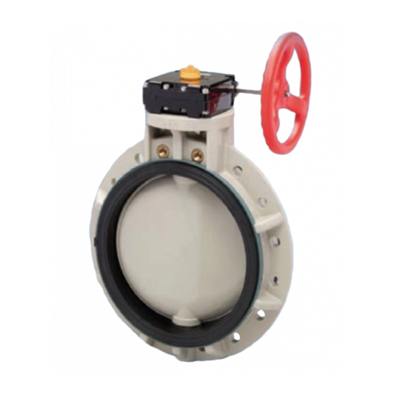
Butterfly Valve Type 56
Parts Identification
Installation Procedure
Caution
1)The valve disc is set in the position indicated by the solid lines in Fig. 5-1 prior to
shipment from the factory. If the valve is opened or closed after unpacking, it must
be reset in this position before installation. Failure to do so will result in damage to
the surface of the valve seat during handling and installation.
2)The valve must not be dropped or come in contact with other objects, as the sealing
surface of the disc and the sealing surface of the valve seat may be damaged.
3)Care must be used during piping installation to ensure that the pipes or flanges are
properly aligned so that the valve disc does not come in contact with them.
Misalignment as shown in Fig. 5-2 will result in damage to the valve.
4)The installed valve should not be opened or closed when foreign matter such as
shavings, etc. are present from system installation. System should be flushed prior
to operating valves.
To avoid interference the piping ID must be equal to or larger than the D dimension
shown in the following chart. If pipe interference is evident spacers or chamfering of
the pipe or fitting is required.
Nominal
Diameter D
Size
(inch)
1-1/2"
1.34
2"
1.77
2-1/2"
2.36
3"
2.80
3/15/02
Nominal
Diameter D
Size
(inch)
4"
3.66
5"
4.65
6"
5.47
8"
7.48
No.
DESCRIPTION
1
Body
2
Disc
3
Seat
4
O-ring (A)
5
O-ring (B)
6
O-ring (C)
7
Stem
8
Stem holder (A)
16
Handle (A)
16a Inserted metal of handle 28
Nominal
Diameter D
Size
(inch)
10"
9.33
12"
11.38
14"
13.39
16"
14.57
Rev B
No. DESCRIPTION
17
Handle lever
18
Pin
19
Spring
20
Washer (A)
21
Bolt (B)
22
Locking plate
23
Screw (B)
24
Cap (A)
25
Gear box
Bolt (C)
Fig. 5-1
NOT RECOMMENDED
RECOMMENDED
Fig. 5-2
Interferrence of the Disc
NOT RECOMMENDED
T56Install
Advertisement
Table of Contents

Related Manuals for Asahi/America 56

Summary of Contents for Asahi/America 56
- Page 1 Butterfly Valve Type 56 Parts Identification DESCRIPTION No. DESCRIPTION Body Handle lever Disc Seat Spring O-ring (A) Washer (A) O-ring (B) Bolt (B) O-ring (C) Locking plate Stem Screw (B) Stem holder (A) Cap (A) Handle (A) Gear box 16a Inserted metal of handle 28...
- Page 2 Procedure Fig. 5-3 1) Install the valve between flanges with the valve slightly open. (Refer to Fig. 5-3) 2) Insert bolts, nuts and washers and tighten the bolts and nuts temporarily by hand. 3) Open the valve fully to check for pipe interference before fully tightening the bolts. The parallelism and axial misalignment of the flange surface should be under the values shown in the following table to prevent damage to the valve.
- Page 3 Adjustment Procedure for Travel Stop Gear Type The adjustments for full-opened and full-closed position are preset at the factory. If adjustment is required refer to the following procedure: Adjustment for Full-Closed (Full-Opened) Position 1) Remove the protective rubber caps 2) Loosen the stop hex-bolt with an allen wrench. 3) Adjust the disc of valve to the required position.
- Page 4 Replace the stem. If you would like more details about this valve, please request the O & M User’s Manual. ® ASAHI/AMERICA 35 Green Street, P.O. Box 653, Malden, MA 02148 • Tel: (781) 321-5409 • Fax: (781) 321-4421 3/15/02...
Need help?
Do you have a question about the 56 and is the answer not in the manual?
Questions and answers