
Related Manuals for Palas PMFT 1000

Summary of Contents for Palas PMFT 1000
- Page 1 Filter Media Test Rig PMFT 1000 / PMFT 1000 M Operating Manual For specialized users 6924-en_V1.5_03/21 V1.5...
- Page 2 Copyright For all information in this technical document as well as drawings and technical descriptions provided by us, Palas GmbH reserves all proprietary and intellectual property rights. Duplication or dissemination to third parties without our prior written consent is prohibited.
-
Page 3: Table Of Contents
10 Obligations of the user 10 Product description 11 Main components of PMFT 1000 test rig 11 Main components of PMFT 1000 M test rig 11 Holder for filter media and respiratory masks 13 3.3.1 Adapter for respiratory masks 13 3.3.2... - Page 4 Table of contents 6.4.3 Measurement menu 51 6.4.4 Special menu 52 6.4.5 Result menu 56 Efficiency test based on EN 13274-7 58 Breath resistance test based on EN 149 59 Valve function test of respiratory masks based on EN 149 61 Operation with discharge system – upgrade kit 7037 62 Operation with aerosol generator AGK 2000 –...
-
Page 5: About This Manual
Validity of the manual This manual is valid for the following models of test rigs: • PMFT 1000 • PMFT 1000 M Related documents The operating instructions for the following devices are essential components of the system PMFT 1000: •... -
Page 6: Presentation Rules
1 About this manual Presentation rules The following presentations are used in this manual: Text Product names and product descriptions Example: Fidas Cross-references to other documents Example: Information about … is found in the manual for the … Menu items Text Example: Shut Down System Selection and settings Example: Start measuring with Record... -
Page 7: For Your Safety
2 For your safety For your safety Hazards and safety instructions Qualified person Only a properly qualified person may perform installation, commissioning and any other work on the device. Follow the generally accepted codes of practice when installing the device. Preventive measures to Cables and lines that are not laid properly near the test rig can pose a avoid stumbling and hazard. - Page 8 4 Always operate the device alone to prevent another person from being injured. Repairs Do not attempt to repair any components that serve a safety function. Use only original Palas parts when replacing components. Safety instructions on Never remove or cover the safety stickers on the device. The stickers device have to remain legible for the entire service life of the device.
-
Page 9: Warnings
2 For your safety Warnings The warnings in this manual are highlighted with pictographs and signal words. The severity of a hazard is indicated by the pictograph and signal word. Layout of the warnings The warnings that precede each action are shown as follows: DANGER Type and source of the hazard Explanation of type and source of the hazard / description of... -
Page 10: Regulations
2 For your safety Regulations Observe the following regulations and directives: Statutory regulations • Legal regulations for accident prevention • Legal regulations for environmental protection • Employer's Liability Insurance Association provisions Standards and directives • The applicable safety requirements according to DIN, EN, and VDE Obligations of the user To ensure proper functioning of the device, observe the following: Carefully read through the manual before using the device. -
Page 11: Product Description
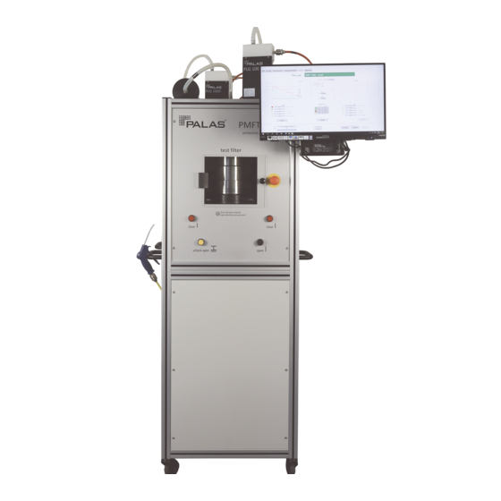
3 Product description Product description Main components of PMFT 1000 test rig Main components of PMFT 1000 test rig 1 Desktop PC and touch screen 2 Emergency-off button 3 Operating elements for filter 4 Aerosol spectrometer holder Promo 1000 5 Aerosol sensor welas 1200... - Page 12 3 Product description Main components of PMFT 1000 M test rig Main components of PMFT 1000 M test rig 1 Desktop PC and touch screen 2 Emergency-off button 3 Operating elements for filter 4 Dilution system VKL 27 holder 5 Aerosol spectrometer Promo...
-
Page 13: Holder For Filter Media And Respiratory Masks
3 Product description Holder for filter media and respiratory masks 3.3.1 Adapter for respiratory masks An adapter consisting of two rings is needed to test convex-shaped respiratory masks. Adapter for respiratory masks in two different position: Top: position 1, bottom: position 2 1 Filter holder 2 Respiratory mask 3 Narrow adapter ring... -
Page 14: Universal Filter Adapter
3 Product description 3.3.2 Universal filter adapter Specially shaped respiratory masks and filters can be placed on the universal filter adapter. The filter holder immobilizes the filter medium during measurement. Universal filter adapter in filter channel 3.3.3 Support grid as surface for flat filter media Flat filter media can be placed directly on the support grid. -
Page 15: Use
3 Product description 3.4.1 Intended use The device is manufactured and tested according to good engineering practices and the recognized safety rules. In order to avoid hazards to yourself or third parties and damage to the device and other assets, only use the device properly and as intended. -
Page 16: Improper Use
3 Product description 3.4.2 Improper use The device is not intended for use by the following persons: • Persons with limited physical, sensory or mental abilities • Persons lacking the required qualification, experience or knowledge • Persons under 18 years of age The device is not intended to be used to test non-permeable filter media. -
Page 17: Functional Description
3 Product description Functional description The PMFT 1000 / PMFT 1000 P is a modularly designed filter testing system for respiratory masks. The test rig works in pressure mode. Aerosol generators The aerosol is created by two aerosol generators. The aerosol generators are triggered by a solenoid valve and switched accordingly. -
Page 18: Environmental Conditions
3 Product description Testing procedure There are two ways to place respiratory masks in the filter holder: • With the exterior (curvature) facing up: simulates inhalation. • With the exterior (curvature) facing down: simulates exhalation. The software contains the following testing routines: •... -
Page 19: Scope Of Delivery
• Aerosol spectrometer Promo 1000 • Aerosol sensor welas 1200 + cleaning kit • Dilution system VKL 100 Model PMFT 1000 M • Test rig with filter holder • Desktop PC and touch screen with control software • 2 aerosol generators PLG 1000 •... -
Page 20: Optional Accessories
3 Product description Optional accessories The following optional accessories are available for purchase: • Set: isokinetic sampling probes • Testing head “Mas-Q-Head” (only for PMFT 1000 M) • Label printer ZEBRA ZD410 • Upgrade kit 7037 for testing based on the standards 42 CFR 84 and GB 2626 (discharge system CD 2000 + temperature and moisture sensors) •... -
Page 21: Dimensions
3 Product description 3.10 Dimensions Dimensions of test rig – all dimensions in millimeters 3.11 Minimum clearance 4 Verify that there is enough space between the device and the ceiling and walls to be able to properly operated and service the device. We recommend a minimum clearance of 1.5 m. -
Page 22: Initial Commissioning
4 Initial commissioning Initial commissioning Connecting test rig 4.1.1 Back panel of test rig The connections for compressed air and power as well as the fitting for exhaust air are located on the back panel of the test rig. CAUTION Risk of stumbling and falling Cables and lines that are not laid properly near the test rig can pose a hazard. - Page 23 4 Initial commissioning Back panel of test rig 1 Outputs for unregulated 2 Power strip for all electrical compressed air consumers except for the (COMPRESSED AIR OUT) desktop PC. following the maintenance unit. 3 quick couplers NG8 For connecting the dilution system. 3 Aerosol outlet fitting 4 Output for unregulated (EXHAUST AIR).
-
Page 24: Connection Diagram For Pmft 1000
6 - 8 bar NW: 13 mm MAX: 230V / 50/60 Hz AC 8 bar Outlet Filter / 230V / 50/60 Hz AC Cleaner Promo 1000 6 - 8 bar ETHERNET welas 1200 Connection diagram for PMFT 1000; not to scale, simplified 6924-en_V1.5_03/21... -
Page 25: Pmft 1000 - Connections For Individual Components
4 Initial commissioning 4.1.3 PMFT 1000 – Connections for individual components Connections on PLG 1000 The retention time tube is installed between the PLG 1000 that works with salt and the filter channel. The hose line from the other PLG 1000 is connected directly to the filter channel. - Page 26 4 Initial commissioning Connections on VKL 100 and Promo 1000 Connections on VKL 100 and Promo 1000 1 Promo 1000 2 Hose line (NW 6 mm) from outlet of aerosol sensor welas 1200 to plug connection “Suction” 3 Line “Detector” to aerosol 4 Line “Lamp” to aerosol sensor sensor 5 Compressed air line 6 Exhaust fitting for hose ID (NW 13 mm), 6 –...
- Page 27 4 Initial commissioning Connections on back of Promo 1000 1 Control lines “MFC sample 2 Ethernet: LAN cable, flow,” “sample flow switch” and connection to PC “MFC gen” 3 Power cable 4 Hose line from aerosol outlet The control lines from inside of the test rig are labeled. Connect the lines to the corresponding sockets on the back of the Promo 1000.
- Page 28 4 Initial commissioning Connections on aerosol sensor welas 1200 Connections on aerosol sensor welas 1200 1 Hose line (NW 8 mm) to 2 Aerosol sensor welas 1200 dilution system VKL 100 3 Hose line (NW 6 mm) to plug 4 Lines “Detector” and “Lamp” to connection “Suction” on aerosol spectrometer aerosol spectrometer 6924-en_V1.5_03/21...
-
Page 29: Connection Diagram For Pmft 1000 M
6 - 8 bar NW: 13 mm MAX: 230V / 50/60 Hz AC 8 bar Outlet Filter / 230V / 50/60 Hz AC Cleaner Filter / Cleaner Promo LED 2300 ETHERNET Connection diagram for PMFT 1000 M; not to scale, simplified 6924-en_V1.5_03/21... -
Page 30: Pmft 1000 M - Connections For Individual Components
4 Initial commissioning 4.1.5 PMFT 1000 M – Connections for individual components Connections on PLG 1000 The retention time tube is installed between the PLG 1000 that works with salt and the filter channel. The hose line from the other PLG 1000 is connected directly to the filter channel. - Page 31 4 Initial commissioning Connection between Promo LED 2300 and VKL 27 Connection between Promo LED 2300 and VKL 27 1 VKL 27 2 Connecting hose, NW 10 mm 3 Promo LED 2300 4 Exhaust hose, inner diameter: 22 mm (not included in scope of delivery) The Promo LED 2300 should be positioned such the hose from the VKL 27 runs as close to vertical as possible.
- Page 32 4 Initial commissioning Connection between VKL 27 and sampling tube Connection between VKL 27 and sampling tube 1 Sampling tube (outer diameter: 2 VKL 27 8 mm) 3 Exhaust fitting exhaust air Compressed air line (NW 8 mm), from back of test rig (connected to pressure controller, 2 bar) The exhaust fitting VKL 27 must be connected when depressurized to a filter...
- Page 33 4 Initial commissioning VKL 27 connection to compressed air Pressure controller and compressed air line to VKL 27 - standard configuration 1 Pressure controller; set to 2 bar 2 Compressed air line (NW 8 mm) to VKL 27 6924-en_V1.5_03/21...
- Page 34 4 Initial commissioning Pressure controller and compressed air line to VKL 27 with toggle switch 1 Pressure controller; set to 2 bar 2 Compressed air line (NW 8 mm) to VKL 27 3 Toggle switch to turn on and off the VKL 27. Can be integrated into line as required. 6924-en_V1.5_03/21...
-
Page 35: Attaching And Connecting Desktop Pc With Touch Screen
4 Initial commissioning 4.1.6 Attaching and connecting desktop PC with touch screen Mounting Attaching desktop PC with touch screen to hinged arm on test rig Remove the bottom two screws from the hinged arm on the test rig. Hang the desktop PC with touch screen in the top two screws. Secure the two bottom two screws in the hinged arm such that the PC can still be pivoted. - Page 36 4 Initial commissioning Connecting Connections on desktop PC – left side 1 Receptacle for WiFi antenna 2 LAN cable to aerosol spectrometer (Promo) 3 USB cable to touch screen 4 Cable to power pack 5 HDMI cable to touch screen 6 USB cable to pressure sensor (option) Important: If a pressure sensor is to be connected: Use only the back, upper USB...
- Page 37 4 Initial commissioning Connections on desktop PC and on touch screen – right side 1 Power cable for the touch 2 Power cable for the PC screen 4 Connect all cables as shown in the illustrations. Important: The desktop PC power cable may not be connected to the power strip on the panel.
-
Page 38: Connecting Discharge System Cd 2000 (Option)
4 Initial commissioning 4.1.7 Connecting discharge system CD 2000 (option) The discharge system CD 2000 controller must be connected to the cable harness made up of the following three cables: cable NEG, cable POS and a ground cable. Connect the power cable to the power strip. Connections on the discharge system CD 2000 controller (option) Setting Up Test Rig The test rig has to be set up on a flat surface, sturdy enough that it will not... -
Page 39: Operating And Display Elements
5 Operating and display elements Operating and display elements Operating elements on electrical cabinet Operating elements on electrical cabinet 1 Green button. Switches on the 2 Main switch. Switches ON or power supply in the electrical OFF all electrical components cabinet. in the electrical cabinet and the plugs. -
Page 40: Emergency-Off Button
5 Operating and display elements Operating elements on the front 1 Emergency-off button. 2 Knob on protective door. Pull Depressurizes the pneumatic the knob to open the protective system and switches off the door. The filter holder is components in the electrical depressurized when the cabinet. - Page 41 5 Operating and display elements Emergency-off button The emergency-off button is pressed in upon delivery of the test rig. Before switching on the test rig for the first time, pull the emergency-off button out to unlock it. 6924-en_V1.5_03/21...
-
Page 42: Operation And Settings
6 Operation and settings Operation and settings Switching on test rig Proceed as follows to switch on the test rig: Verify that the emergency off button is unlocked. Set the main switch on the electrical cabinet to ON. ð The red button on the electrical cabinet lights up. Press the green button. - Page 43 In addition to the software version, the menu init shows the date until which the test rig calibration is valid. When calibration expires, the test ring should be calibrated again by Palas specialists. Contact Palas or a sales partner for this purpose.
-
Page 44: Notes On Operation Of Aerosol Sensors
6 Operation and settings Notes on operation of aerosol sensors Concentration of saline aerosols Use saline aerosols with a concentration of 5% for testing at the plant and for calibration purposes. Experience has shown that this concentration provides reproducible and precise measurement results. We recommend using this concentration. -
Page 45: Opening And Closing Filter Holder
6 Operation and settings Opening and closing filter holder DANGER Risk of crushing limbs when opening and closing the filter holder When the filter is opened and closed, surfaces and edges that can cause pinching and cutting are exposed. The two-hand control for closing the device protects only the person pressing the buttons. -
Page 46: Closing Filter Holder
6 Operation and settings 6.3.3 Closing filter holder DANGER Risk of crushing limbs when opening and closing the filter holder When the filter is opened and closed, surfaces and edges that can cause pinching and cutting are exposed. The two-hand control for closing the device protects only the person pressing the buttons. -
Page 47: Software Pmft1000
6 Operation and settings Software PMFT1000 The software PMFT1000 for operating the test rig can be found in the directory Desktop > PMFT1000 on the PC. Directory Desktop > PMFT1000 If the software is included in an autostart routine, it starts automatically when the operating system is started. -
Page 48: Script Menu
6 Operation and settings 6.4.1 Script menu 123 456 789 Mask Maker unlimited Jane Doe Menu script 1 Input and display field for 2 Input and display field with numerical information such as multiple lines for specific batch numbers information 3 Repeat: Repeats the last 4 Cancel: Cancels a testing testing routine. - Page 49 6 Operation and settings In the script menu, test routines can be started by selecting the respective button. There are four standard testing routines: Button Description Additional information Starts the testing routine for an efficiency test Efficiency Test Efficiency test based on EN with a saline aerosol based on EN 13274- 7.
-
Page 50: Test Bench Menu
6 Operation and settings 6.4.2 Test bench menu Measured values can be observed and settings for tests changed in the menu test bench. Test bench menu Buttons and Description input fields Switches between saline aerosol and oil aerosol. salt – oil Defines the flow rate of the aerosol (setpoint) generator flow Defines the total flow rate (setpoint). -
Page 51: Measurement Menu
6 Operation and settings 6.4.3 Measurement menu Menu measurement The menu Measurement shows the following information: • Current measured values • Partial steps of testing routine • Measurement progress 6924-en_V1.5_03/21... -
Page 52: Special Menu
6 Operation and settings 6.4.4 Special menu The menu special is visible only to operators signed in with a special name. The default name is tbd. The name can be changed by changing the entry Specialist = tbd in the file PMFT1000.ini. The menu edit mask types can be accessed from this menu. - Page 53 6 Operation and settings 6.4.4.1 Edit mask types menu This menu shows the defined mask types. Each mask type contains at least the following information: • Abbreviated name of mask type (“alias”) • Manufacturer • Model Menu edit mask types Button Feature Opens the add new mask type menu, which edit...
- Page 54 6 Operation and settings Add new mask type menu Data pertaining to existing mask types can be changed or new mask types can be created in the add new mask type menu. Extralarge-1 MyMask Safebreath white Menu add new mask type Button Feature Abbreviated name of mask type.
- Page 55 6 Operation and settings Fields for limits (“Upper limits”) Parameter Meaning P_Specific_Penetration Penetration value for particle size 150 nm P_Ph_45° [%] Converted penetration value for the measuring method “scattered light measurement at 45°” P_M [%] Converted penetration value for the measuring method “flame photometer”...
-
Page 56: Result Menu
6 Operation and settings 6.4.5 Result menu Menu result The menu result appears at the end of a testing routine. Parameters and results of efficiency tests Parameter Meaning P_SARS-CoV-2 [%]* Penetration value for particle size 150 nm P_m [%] Converted penetration value for the measuring method “flame photometer”... - Page 57 6 Operation and settings Results of breath resistance testing Parameter Meaning dP 0 [Pa] Differential pressure at an inhalation flow rate of approx. 30 l/min dP 1 [Pa] Differential pressure at an inhalation flow rate of approx. 95 l/min dP 2 [Pa] Differential pressure at an exhalation flow rate of approx.
-
Page 58: Efficiency Test Based On En 13274-7
6 Operation and settings Efficiency test based on EN 13274-7 There are two testing routines available for testing respiratory masks based on EN 13274- 7: • Efficiency Test (salt) = Testing with saline aerosol • Efficiency Test (oil) = Testing with oil aerosol Testing sequence: 1. -
Page 59: Breath Resistance Test Based On En
6 Operation and settings Breath resistance test based on EN 149 The following values are saved in the testing routine Breath Resistance: Volume flow rate 1 when inhaling (curvature of respiratory mask up): 95 l/ min. Volume flow rate 2 when inhaling (curvature of respiratory mask up): 30 l/ min. - Page 60 6 Operation and settings Performing a test Touch the respective button to start a testing routine. ð The window Operator Name appears. Enter the name and confirm with the enter key. ð The window please choose a type appears. Touch >choose< and confirm with ok to select a predefined type of mask.
-
Page 61: Valve Function Test Of Respiratory Masks Based On En
6 Operation and settings Valve function test of respiratory masks based on EN 149 The following value is saved in the testing routine FFP 3 Valve Test: Volume flow rate: 300 l/min. The curvature of the respiratory mask has to face down on the filter holder for this measurement. -
Page 62: Operation With Discharge System - Upgrade Kit 7037
6 Operation and settings Operation with discharge system – upgrade kit 7037 Tests in line with the standards 42 CFR 84 (NIOSH) / GB 2626 (SAC) There is an optional upgrade kit available for tests in line with the standards 42 CFR 84 (NIOSH) / GB 2626 (SAC). The upgrade kit includes: •... - Page 63 6 Operation and settings Adding a discharge system When the discharge system CD 2000 B is added, some of the calculation parameters have to be modified for the results to still be accurate. For the measured values to be correct, the factor for the mass concentration has to be determined anew;...
-
Page 64: Operation With Aerosol Generator Agk 2000 - Upgrade Kit 7086
6 Operation and settings Operation with aerosol generator AGK 2000 – upgrade kit 7086 Tests in line with the standard ASTM F2299-3 There is an optional upgrade kit available for tests in line with the standard ASTM F2299-3. Prerequisite: Upgrade kit 7037 is installed. Upgrade kit 7086 includes: •... - Page 65 6 Operation and settings Producing PSL solutions PSL solutions can be made from latex concentrate and demineralized water. The following PSL solutions produce good results: PSL solution Base fluid Latex concentrate PSL solution, Demineralized water 25 drops 3 µm (pure water), 100 ml (≈...
-
Page 66: Script Files
Changes should be made only by authorized persons who have extended process engineering skills in addition to programming skills. Palas explicitly points out that the operator is responsible for the changes in script files. Palas will assume no liability for faulty measurement results, damage to equipment or any consequent damage or lost profit. - Page 67 6 Operation and settings The script file PMFT_ScriptButtonCancel.txt is not a testing routine. This file ensures that flow rates are set to 0 when a process is canceled. Other script files in the directory Further Additional script files can be saved in the directory Further. Up to 12 additional scripts are possible.
-
Page 68: 6.10.2 Structure Of Script Files
6 Operation and settings 6.10.2 Structure of script files Each script file contains the following elements: • Three section markers • The command line script_name = for the name of the script • Several command lines that control the course of the testing routine Additional lines containing comments may already be included or can be added. - Page 69 6 Operation and settings Collection of command lines All of the the available command lines that control the course are in the file CMDs.txt. Each command line consists of the actual command (first element) and of one or more parameters separated by the separator |. Sample command line in the file CMDs.txt 1 Command 2 Separator...
-
Page 70: 6.10.3 Command Lines - Explanation Of Commands
6 Operation and settings 6.10.3 Command lines – explanation of commands This section describes the command lines saved in the file CMDs.txt. WAIT | Duration[s] Function: Specification of a waiting time. Used e.g. to stabilize flow rates and concentrations. Valid values for parameter 1 Meaning | Duration[s] Whole number... - Page 71 6 Operation and settings SET_PSD | usedPSD(EN149, 42CFR84, RAW, CUSTOMER values(X_g[µm] | Sigma)) Function: Selection of the the method for calculating particle size distribution. Valid values for parameter 1 Meaning | usedPSD(EN149, 42CFR84, RAW, CUSTOMER values(X_g[µm] | Sigma)) EN149 A calculation method based on the standard EN149 is applied.
- Page 72 6 Operation and settings SET_SPECIFIC_PENETRATION | Name[txt] | Size[µm] Function: Determination of a specific particle size from the penetration curve to appear in the report. Valid values for parameter 1 Meaning | Name[txt] Text Name of specific particle size Valid values for parameter 2 Meaning | Size[µm] Decimal number (separator = period) Specific particle size in µm.
- Page 73 6 Operation and settings MEASURE_PRESSURE | Duration[s] | register(dP0, dP1, dP2, dP3) Function: Measurement of differential pressure. Valid values for parameter 1 Meaning | Duration[s] Whole number Duration of measurement in seconds. Valid values for parameter 2 Meaning | register(dP0, dP1, dP2, dP3) First value of differential pressure measurement when inhaling.
- Page 74 6 Operation and settings MEASURE_DISTRIBUTION | Duration[s] | source(UPSTREAM, DOWNSTREAM) Function: Measurement of number concentration and particle distribution. Valid values for parameter 1 Meaning | Duration[s] Whole number Duration of measurement in seconds. Valid values for parameter 2 Meaning | source(UPSTREAM, DOWNSTREAM) UPSTREAM Measurement of number...
- Page 75 6 Operation and settings MESSAGE | buttonText | Message Text Function: Creation of a dialog window on the screen. Valid values for parameter 1 Meaning | buttonText Text (max. 9 characters) Text on window button. Example: “done” Valid values for parameter 2 Meaning | Message Text Text...
- Page 76 6 Operation and settings QUESTION | IoButtonText | nIoButtonText | Question Text | register(VALVE, RIBBON) Function: Creation of a dialog window with a question to the operator. Valid values for parameter 1 Meaning | IoButtonText Text (max. 9 characters) Text for positive reply from the operator (OK).
- Page 77 6 Operation and settings CLEAR | result(ALL, OIL, SALT, USER, PRESS&FLOW) Deleting measurement results or operator input from current display. Valid values for parameter 1 Meaning | result(ALL, OIL, SALT, USER, PRESS&FLOW) All measurement results and operator input. Measurement results for oil aerosol. SALT Measurement results for saline aerosol.
- Page 78 6 Operation and settings CORRECTION_MASS | type(SALT, OIL) Function: Correction of flow rate to optimize mass concentration. Valid values for parameter 1 Meaning | type(SALT, OIL) SALT Correction of flow rate for saline aerosol. Correction of flow rate for oil aerosol. BEEP | duration[ms](500) | frequency[Hz] (2000) Function: Creation of an acoustic signal.
-
Page 79: 6.10.4 Sample Script With Explanations
6 Operation and settings 6.10.4 Sample script with explanations The following illustration shows an example of the single commands of a script file. Sample script 6924-en_V1.5_03/21... - Page 80 6 Operation and settings 1 Name of script 2 Last result for saline aerosol is deleted 3 Dialog window: Operator input 4 Dialog window: Select a mask 5 Dialog window: Batch input 6 Prompt to close filter holder 7 Select aerosol: Salt aerosol 8 Set total flow rate 9 Waiting time: 5 seconds 10 Set aerosol flow rate...
-
Page 81: Log Files With Measured Data
6 Operation and settings 6.11 Log files with measured data The data from each measurement is saved in log files. Storage location: Desktop > PMFT1000 > Reports > LOG. Format: CSV (separator: semicolon) Storage location and components of names of log files 1 Short description of mask type 2 Year and month (YYYY-MM) (“alias”) or n.n. - Page 82 6 Operation and settings Parameter Explanation Main air SET [l/min] Total volume flow rate – setpoint Main air [l/min] Total volume flow rate – actual value Generator air SET [l/min] Volume flow rate of aerosol – setpoint Generator air [l/min] Volume flow rate of aerosol – actual value rel.
- Page 83 6 Operation and settings Parameter Explanation Efficiency Test main air [l/min] Efficiency test: Total volume flow rate Efficiency Test differential Efficiency test: Differential pressure pressure [Pa] Smoothing Distribution Smoothing factor for distribution curve. Used_PSD Particle size distribution (e.g.. EN149 or 42CFR84) applied to calculate P_m and P_Ph_45°...
- Page 84 6 Operation and settings Parameter Explanation P_Ph_45° (RAW) [%] Photometric -based penetration value with the distribution generated by the specific algorithm of the PMFT. P(µm) [%] Identifier for the data range “Particle size distribution.” The data range begins with the next column. 0.093298 Percentage number of particles of data channel with the average size 0.093298 µm.
-
Page 85: Establishing Remote Connection To Aerosol Spectrometer
6 Operation and settings 6.12 Establishing remote connection to aerosol spectrometer A remote connection allows the aerosol spectrometer to be operated via the touch screen on the test rig. Prerequisite: The software PMFT1000 is closed. To create the remote connection: Ensure that the software PMFT1000 is closed. Open the Windows app “Remote desktop connection.”... - Page 86 6 Operation and settings Windows login screen for aerosol spectrometer 4 Select “OK” (There is no password). ð The aerosol spectrometer firmware appears. 6924-en_V1.5_03/21...
-
Page 87: Closing Software And Switching Off Devices
6 Operation and settings 6.13 Closing Software and Switching Off Devices Exit the following systems by touching the X at the top right corner of the software PMFT1000: • Software PMFT1000 • Operating system of the desktop PC • Firmware of the aerosol spectrometer Promo •... - Page 88 6 Operation and settings Switching off all test rig systems and devices Proceed as follows to switch off all test rig systems and devices: Move the filter holder up. Verify that the flow rates main air flow sp and generator flow sp are set to zero. Touch the X in the top right corner of the software PMFT1000.
-
Page 89: What To Do When
6 Operation and settings 6.14 What to do when… This section contains answers to some common questions related to using the device. If the stated measures do not remedy the issue, contact Palas or your responsible representative. Problem Explanation/action Testing routine Breath The differential pressure measured can only be compared if the measurement conditions are the same. -
Page 90: Maintenance
Palas specialists or by persons or organizations authorized by Palas. Unauthorized changes or modifications will lead to loss of warranty. Palas will not be liable for damage caused by unauthorized changes or modifications. -
Page 91: Dilution System Vkl 100 - Cleaning Suction Nozzle
7 Maintenance Dilution system VKL 100 – cleaning suction nozzle The suction nozzle of the dilution system VKL 100 has a very small inner diameter and can become even more restricted due to salt residue. Restriction caused by salt particles severely impairs nozzle functioning. For this reason, remove the nozzle daily and clean it with compressed air. - Page 92 7 Maintenance Cleaning the nozzle Cleaning the nozzle with compressed air is usually sufficient. The nozzle can be cleaned in an ultrasound bath in the event of stubborn pollution. Recommended cleaning fluid: isopropanol. Cleaning suction nozzle with compressed air Installation Install the nozzle on the dilution system by reversing the order of removal, then connect the hose from the sampling tube to the suction nozzle.
-
Page 93: Calibrating Aerosol Sensor
7 Maintenance Calibrating aerosol sensor Calibration interval We recommend calibrating the aerosol sensor every week. Operating temperature Ensure that the aerosol spectrometer is at operating temperature during calibration. It will be at operating temperature after having remained on for at least 30 minutes. If the device is calibrated right after it is switched on, calibration will not be accurate. - Page 94 Only a small amount of the dust is needed for the calibration 1500 process. MonoDust 1500 can be ordered from Palas or your sales partner. The label on the container as well as the certificate for the calibration dust indicate reference values (setpoint raw channel) needed to calibrate...
-
Page 95: Preparations For Calibration
7 Maintenance 7.2.1 Preparations for calibration To calibrate the aerosol sensor, use the firmware Mas-Q-Check of the aerosol spectrometer (Promo 1000 or Promo LED 2300). The firmware can be operated either directly on the touch screen of the aerosol spectrometer or via the remote connection. The software PMFT1000 has to be closed to be able to use a remote connection. - Page 96 7 Maintenance Firmware Mas-Q-Check: Expert user menu 4 Touch sensor/calibration. ð A menu showing sensor data opens. Firmware Mas-Q-Check: Sensor/calibration Check that the primary pressure is set to 2.0 bar on the dilution system VKL 100 (default). Check the value of the parameter dilution/calibration factor: The value has to be the same as the “Dilution factor W”...
- Page 97 7 Maintenance Checking aerosol sensor zero point To check the zero point, a special filter (HEPA filter) that holds back all particles from the air is placed on the aerosol inlet tube of the aerosol sensor. The graphs raw data distribution and time distribution in the calibration menu may not show any signals for several seconds.
-
Page 98: Calibrating Particle Size
7 Maintenance 7.2.2 Calibrating particle size Prerequisites • The device’s zero point has been checked. • The calibration menu is open. Calibration interval We recommend calibrating the aerosol sensor every week. Administering calibration dust Connect a hose to the aerosol inlet of the aerosol sensor. Hold the hose in the container of MonoDust 1500. - Page 99 7 Maintenance Calibrating particle size Use the reference value setpoint raw channel, which can be found on the label of the calibration dust container and on the certificate for the calibration dust. Calibration is successful when the measured peak at is identical to the value of the raw data channel, found on the label of the calibration dust container.
-
Page 100: Calibrating Particle Velocity
7 Maintenance 7.2.3 Calibrating particle velocity Calibration of the particle velocity is applicable only when using a Promo 1000 as the aerosol spectrometer. Prerequisites • The device’s zero point has been checked. • The calibration menu is open. Calibration interval We recommend calibrating the aerosol sensor every week. Administering calibration dust Connect a hose to the aerosol inlet of the aerosol sensor. - Page 101 7 Maintenance Calibrating particle velocity Edit the right scale value in the lower diagram: Set the value to 100. Use the blue cursor keys to move the cursor to the right signal peak in the lower graph. ð The values of the parameters velocity at cursor (dust) and particle velocity (menu sensor/calibration) have to be the same.
-
Page 102: Maintenance Unit For Compressed Air
7 Maintenance Maintenance unit for compressed air The maintenance unit for the compressed air is located inside of the test rig. Maintenance unit for compressed air inside of test rig 1 Filter 5 µm inside of 2 Drain screw condensate container 3 Drain screw 4 Filter 0.01 µm inside of condensate container 6924-en_V1.5_03/21... - Page 103 7 Maintenance The maintenance unit can be accessed by detaching the side panel. Side panel with fastening screws Weekly maintenance Check the level in the condensate container at least once a week. Empty collected condensate into a suitable vessel when necessary. Proceed as follows: Detach the quick coupling from the compressed air supply to depressurize the test rig.
- Page 104 7 Maintenance Annual maintenance Replace the filters in the maintenance unit once a year. Proceed as follows: Detach the quick coupling from the compressed air supply to depressurize the test rig. Detach the side panel. Wait until the maintenance unit is completely depressurized, The manometer shows 0 bar.
-
Page 105: Checking Differential Pressure
7 Maintenance Checking differential pressure The following procedure can be used to test the following things and others: • Check for leakage (e.g. at the seals or plug connections). • Check whether volume flow rate is calibrated correctly. • Check that the pump is working properly. Prerequisites The test rig has to be ready for operation. - Page 106 The measurement result must be within the tolerance indicated on the calibration certificate (“Allowable range”). If the result is not within the tolerance, there is leakage or some other fault. Contact Palas or your sales partner in this case. 6924-en_V1.5_03/21...
-
Page 107: Determining The Factor For Mass Concentration
7 Maintenance Determining the factor for mass concentration Objective The aerosol spectrometer Promo works with a factor for the mass concentration. The factor has been set at the factory. It has to be checked or specified anew occasionally. Each type of aerosol (saline or oil) has its own factor. - Page 108 7 Maintenance Prerequisites • The aerosol spectrometer Promo and the dilution system VKL 100 are switched on. • The liquid for which the factor for the mass concentration is to be determined is contained in the aerosol generator. • The software PMFT1000 is closed. •...
- Page 109 7 Maintenance Entering flow rates X,00 salt | oil 95,00 Menu test bench Ensure that the filter holder is closed. Open the menu test bench. Verify that the correct medium for the generator is entered. “salt” for saline aerosol / “oil” for oil aerosol Enter the value 95 l/min for the parameter main air flow sp.
- Page 110 7 Maintenance Aerosol production without filter – first measurement Window “Info” with the mass concentrations (F12 or Fn + F12) 1 Duration of averaging mass 2 Measured mass concentration concentration. Default: raw of aerosol spectrometer; 60 seconds updated every second 3 Measured mass concentration 4 Calculated mass concentration raw(XX s)of aerosol factored(XX s) of aerosol...
- Page 111 7 Maintenance Weighing empty round filters Two round filters in a precision scale Place two round filters in a precision scale and weight them. Check the flow direction before doing this. Note the measured value as mass m 6924-en_V1.5_03/21...
- Page 112 7 Maintenance Loading and weighing the round filters The support grid has to be in place in the filter holder shaft to be able to load the round filters. Support grid and round filters in filter holder shaft 1 Support grid 2 Two round filters Open the filter holder.
- Page 113 7 Maintenance Remove the two round filters and the support grid. Close the filter holder. 10. Weigh the two round filters and make a note of the value as mass m Aerosol production without filter – second measurement Wait 10 minutes. Read the parameter raw(600 s) and write it down (value 2 for calculation of C m,Promo Calculate an average of the values 1 and 2.
- Page 114 7 Maintenance Setting flow rate for aerosol generator The flow rate for the aerosol generator must be set such that a mass concentration in compliance with the standard EN 149 is achieved: Target value for the mass concentration of saline aerosol: 8 mg/m ±...
- Page 115 7 Maintenance Checking results To check whether all of the results have been saved correctly, start an efficiency test and check the parameter upstream mass. The value of the parameter has to be within the normal range. The efficiency test can be canceled when the software tells you to insert a mask (load mask).
-
Page 116: Errors
6 bar. If the measures indicated here do not solve the problem or the problem is not included here, please contact Palas or a sales partner. To enable us to process written inquiries as quickly and correctly as possible, please include the following information: •... -
Page 117: Decommissioning
9 Decommissioning Decommissioning To decommission the device when it is no longer needed, proceed as follows: Switch off all components of the test rig. Empty the liquid reservoirs of the aerosol generators. Disconnect the test rig from the power supply (power plug). Disconnect the test rig from the compressed air supply. -
Page 118: Packaging And Transportation
10 Packaging and transportation Packaging and transportation 10.1 Preparing the device To pack, transport, or dispatch the device, it has to be decommissioned (Refer to section Decommissioning). 10.2 Packaging and transportation Package the device securely to exclude damage during transportation. Original packaging For the purpose of shipping, use the original packaging including the protective inner packaging or the original transport case (if applicable). -
Page 119: Declaration Of Conformity
11 Declaration of conformity Declaration of conformity 6924-en_V1.5_03/21... -
Page 120: Technical Specifications
12 Technical specifications Technical specifications Measuring range PMFT 1000 0.10 - 40 µm Measuring range PMFT 1000 0.145 - 40 µm Volume flow rate 1 - 27 m /h (pressure mode) Face velocity 5 - 100 cm/s Differential pressure 0 - 1200 Pa... - Page 122 Palas GmbH Greschbachstraße 3 b 76229 Karlsruhe Germany Tel.: +49 721 96213-0 Fax: +49 721 96213-33 www.palas.de mail(at)palas.de...
Need help?
Do you have a question about the PMFT 1000 and is the answer not in the manual?
Questions and answers