Table of Contents
Advertisement
Advertisement
Table of Contents
Troubleshooting

Subscribe to Our Youtube Channel
Related Manuals for Magnaflux CSV Series


Summary of Contents for Magnaflux CSV Series
- Page 1 CSV SERIES Revised January 2020 www.magnaflux.com Page | 1-0...
-
Page 2: Table Of Contents
Monthly Operator Maintenance ................... 4-2 Periodic Internal Maintenance ..................... 4-2 SECTION 5 – TROUBLESHOOTING ..................... 5-1 Troubleshooting Guide ......................5-2 SECTION 6 – DRAWINGS & SPARE PARTS LIST ............... 6-1 SECTION 7 – HOOD INSTALLATION ................... 7-1 Revised January 2020 www.magnaflux.com Page | 1-1... -
Page 3: General Safety Instructions
GENERAL SAFETY INSTRUCTIONS This manual provides information on how to install, operate, and maintain your Magnaflux magnetic particle inspection machine. Read these instructions carefully before operating or servicing your machine. • Only trained personnel should operate or service this machine. Be familiar with your facility and local procedures as well as Lock Out/Tag Out requirements before working with this machine. -
Page 4: Section 1: Equipment Specifications
A digital ammeter provides a reading of the magnetizing current. The reading is held until the next current “shot” is initiated. Pertinent data (e.g., the unit’s serial number, electrical specifications, and duty cycle rating) may be found on the Magnaflux Data Plate, located on the front side of the unit. Revised January 2020 www.magnaflux.com... -
Page 5: Equipment Specifications
Line Fuse (Amp- Phase eres) CSV-10 Model Input Load Recommended Series Volts AC (Amperes) Line Fuse (Amp- Phase eres) CSV-15 Model Input Load Recommended Series Volts AC (Amperes) Line Fuse (Amp- Phase eres) CSV-20 Revised January 2020 www.magnaflux.com Page | 1-4... - Page 6 15,000 Continuously Reversing CSV-20 20,000 Variable Decaying DC on Output 1 In all cases Seconds “On” Seconds “Off” CSV Series At Maximum Output Capacities Table 1-7. Machine Weight Approximate Weight (Dry) Approximate Weight (Crated) Model No. Pounds Kilograms Pounds Kilograms...
-
Page 7: Equipment Warranty
EQUIPMENT WARRANTY The Equipment Warranty Statement can be found on our Web site at the following link: https://www.magnaflux.com/Files/Corporate/Equipment-Warranty-Statement.pdf Revised January 2020 www.magnaflux.com Page | 1-6... - Page 8 PAGE LEFT BLANK INTENTIONALLY Revised January 2020 www.magnaflux.com Page | 1-7...
-
Page 9: Section 2: Installation And Storage
Consider the following requirements before selecting a permanent location for the inspection unit: 1. A power source of the proper voltage, frequency and phase (as designated on the Magnaflux Data Plate located on the front side of the inspection unit) capable of providing current per the nameplate. - Page 10 The inspection unit as supplied is internally wired for operation from a power source as designated on the Magnaflux Data Plate (located on the front of the inspection unit). When connecting the unit all local codes should be followed. External wiring directions for operation on the designated voltage are as follows: 1.
- Page 11 2. If using the optional 600086 BLACK LIGHT with the integral mag shot button, plug the mag shot cable into the REMOTE MAG socket conveniently located on either end next to the BLACK LIGHT outlets. Figure 2-2 Verification of Functions Revised January 2020 www.magnaflux.com Page | 2-3...
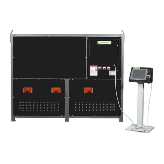
- Page 12 This is called the E-STOP button and shown below as well. Figure 2-4 The standalone pedestal connects to the front panel as shown by the cord in Figure 2-4 on the previous page. Figure 2-5 below shows the standalone pedestal. Revised January 2020 www.magnaflux.com Page | 2-4...
- Page 13 If it shows RECIPE ON instead, as shown in Figure 2-7, the operator would push the RECIPE ON button, and the button would change back to MANUAL ON as shown in Figure 2-6. Revised January 2020 www.magnaflux.com Page | 2-5...
- Page 14 Next, the operator will connect a minimum of 30’ of 1000 MCM for CSV-10 or 30’ of 1000 MCM in parallel with double 30’ 4/0 for CSV-15 to the bus bars on output 1 shown in Figure 2-9. Revised January 2020 www.magnaflux.com Page | 2-6...
- Page 15 The screen below shown in Figure 2-11 will appear, and the parameters for Outputs 1, 2, and 3 are shown. The operator would push the FULL WAVE button located below Output 1 to turn on Output 1. Outputs 2 and 3 Revised January 2020 www.magnaflux.com Page | 2-7...
- Page 16 The Demag Power needs to be set next, and is done the same way as the Mag Power was set up. The operator would push the box next to Demag Power, and enter a value of 25, and then press the blue ENT Revised January 2020 www.magnaflux.com Page | 2-8...
- Page 17 After initiating a magnetizing shot, the operator would then push green DEMAG button located on the main screen, which is located in the bottom center of the screen, and shown below in Figure 2-15. During Revised January 2020 www.magnaflux.com Page | 2-9...
- Page 18 From the main screen, the operator would push the Current Type button located in the bottom left corner of the screen, in the Setup Screens section. This is shown in Figure 2-18 below. Revised January 2020 www.magnaflux.com Page | 2-10...
- Page 19 Mag Power on the screen, and a keypad will appear, as shown below in Figure 2-20. The operator would enter a value of 20, and then push the blue ENT button. The keypad will disappear, and the screen will go back to showing all the outputs. Revised January 2020 www.magnaflux.com Page | 2-11...
- Page 20 This button is shown in Figure 2-21 below. Figure 2-21 On the main screen, as shown in Figure 2-22 below, it will show the amperage output for Output 2, and hold that value. Revised January 2020 www.magnaflux.com Page | 2-12...
- Page 21 Figure 2-23. During demagnetization, a message will appear as shown in Figure 2-24 below. Once the demagnetization cycle is complete, the message will disappear, and the main screen will appear again. Figure 2-23 Figure 2-24 Figure 2-15 Revised January 2020 www.magnaflux.com Page | 2-13...
- Page 22 From the main screen, the operator would push the Current Type button located in the bottom left corner of the screen, in the Setup Screens section. This is shown in Figure 2-26 below. Figure 2-26 Revised January 2020 www.magnaflux.com Page | 2-14...
- Page 23 Mag Power on the screen, and a keypad will appear, as shown below in Figure 2-28. The operator would enter a value of 20, and then push the blue ENT button. The keypad will disappear, and the screen will go back to showing all the outputs. Figure 2-28 Revised January 2020 www.magnaflux.com Page | 2-15...
- Page 24 This button is shown in Figure 2-29 below. Figure 2-29 On the main screen, as shown in Figure 2-30 below, it will show the amperage output for Output 3, and hold that value. Figure 2-30 Revised January 2020 www.magnaflux.com Page | 2-16...
- Page 25 Figure 2-31 Figure 2-32 This concludes the Verification of Functions section. In the event the unit does not function as described in the steps above; consult Section 5 for Troubleshooting. Revised January 2020 www.magnaflux.com Page | 2-17...
-
Page 26: Preparation For Storage Or Shipment
Consolidated Freight Classification Rules that will insure safe transportation to the point of delivery. Mark the crate(s) clearly to identify the contents and denote which side is to be up. Revised January 2020 www.magnaflux.com Page | 2-18... - Page 27 PAGE LEFT BLANK INTENTIONALLY Revised January 2020 www.magnaflux.com Page | 2-19...
-
Page 28: Section 3: Operating Instructions
“Demag” Button on Color Touch Screen Interface · This button, when pressed, initiates the automatic reversing DC demagnetization sequence. Once the button is pressed, the demagnetization cycle continues to completion without interruption. Revised January 2020 www.magnaflux.com Page | 3-1... - Page 29 This is called the E-STOP button and shown below as well. Figure 3-1 The standalone pedestal connects to the front panel as shown by the cord in Figure 3-1 above. Revised January 2020 www.magnaflux.com Page | 3-2...
- Page 30 The unit can be operated in Manual or Recipe mode. When the main screen appears, the MANUAL ON green colored button should appear in the bottom center of the screen. Figure 3-3 Revised January 2020 www.magnaflux.com Page | 3-3...
- Page 31 The Output Edit screen in Figure 3-6 below will appear, and for Outputs 1, 2, and 3, the operator has the option to push the FULL WAVE button or OUTPUT OFF button. This depends on the procedure used to inspect the part, and whether the output should be on or off. Revised January 2020 www.magnaflux.com Page | 3-4...
- Page 32 This is listed below the Mag Power. As shown in Figure 3-8 below, Outputs 2 and 3 do not have the demagnetization optional feature. The operator would push the box located next to the Demag Power button on the screen, and a keypad will appear, as shown in Figure 3-7. Revised January 2020 www.magnaflux.com Page | 3-5...
- Page 33 The keypad will disappear and the screen will go back to as it is shown below. It is highly recommended to set the Mag Shot Time at 0.5 seconds; however, some specifications and parts may dictate a longer Mag Shot Time. Revised January 2020 www.magnaflux.com Page | 3-6...
- Page 34 1, then output 2, and lastly output 3. The length of the mag shot would reflect what was set up on the Output Edit screen. Figure 3-10 Revised January 2020 www.magnaflux.com Page | 3-7...
- Page 35 Once this is complete, the part can be magnetized. To magnetize, the operator would push the magnetizing button located on the standalone pedestal. This button is shown in Figure 3-12 below. Figure 3-12 Revised January 2020 www.magnaflux.com Page | 3-8...
- Page 36 Next, the operator would remove the cables, prods, or clamps from the part, and move the part to the next area based on whether the part passed or failed. The next part can then be brought to the inspection area, and the cables, prods, or clamps connected to it for the next inspection. Revised January 2020 www.magnaflux.com Page | 3-9...
- Page 37 This button is shown below in Figure 3-16, and located in the bottom left of the main screen. Figure 3-16 The Process Parameters screen will appears as shown below in Figure 3-17. Figure 3-17 Revised January 2020 www.magnaflux.com Page | 3-10...
- Page 38 ENT button. It is recommended to set the hour to a value of 8, representing 8 hours, and the minutes to a value of 0. Figure 3-19 Revised January 2020 www.magnaflux.com Page | 3-11...
- Page 39 ENT button after each one. This screen also shows a counter for cycles of the unit. Once these items have been set, the operator would push the GO TO MAIN button to return to the main screen. Revised January 2020 www.magnaflux.com Page | 3-12...
- Page 40 The Utilities screen can also be accessed from the main screen, as shown below in Figure 3-22, in the bottom left corner in the Setup Screens section. The operator would again push the Utilities button. Figure 3-22 Revised January 2020 www.magnaflux.com Page | 3-13...
- Page 41 Figure 3-23 The Edit Login Control Screen will appear as shown below in Figure 3-24. From this screen, the operator name and several levels of security passwords can be selected. Figure 3-24 Revised January 2020 www.magnaflux.com Page | 3-14...
- Page 42 Operator Name. If there are several operators, the up and down green arrows to the left side of the screen would be used to toggle up and down to find the operator name required. Figure 3-26 Revised January 2020 www.magnaflux.com Page | 3-15...
- Page 43 1111. The next three levels are not set, and can be set by the supervisor if necessary. This is shown below as the passwords are shown as 0 on the screen. Figure 3-28 Revised January 2020 www.magnaflux.com Page | 3-16...
- Page 44 Once the passwords are set, the supervisor would push the GO TO MAIN button located on the bottom right corner of the Edit Login Control Screen. The main screen would appear as shown below in Figure 3-30. Figure 3-30 Revised January 2020 www.magnaflux.com Page | 3-17...
- Page 45 This screen below details what each level of access has authority to do. To go back to the main screen, the person would push the GO TO PREV button located on the lower right corner of the screen. Figure 3-32 Revised January 2020 www.magnaflux.com Page | 3-18...
- Page 46 Total Piece Count can be re-set to zero by pushing the RESET PIECE COUNTERS button. Once complete, the operator would push the GO TO MAIN button on the bottom of the screen to return to the main screen. Figure 3-34 Revised January 2020 www.magnaflux.com Page | 3-19...
- Page 47 Figure 3-35 below, the MANUAL ON button is shown, so that button would need to be pushed to change it to show RECIPE ON. Figure 3-35 After pushing the MANUAL ON button, it will change to show RECIPE ON as shown below in Figure 3-36. Figure 3-36 Revised January 2020 www.magnaflux.com Page | 3-20...
- Page 48 3-38. From this screen, the operator can select a recipe to run, edit a recipe, save changes to a recipe, or even transfer settings that are selected in the manual mode to a recipe. Figure 3-38 Revised January 2020 www.magnaflux.com Page | 3-21...
- Page 49 After the recipe name is set, the settings for each output need to be set-up. This is done by pushing on the various boxes OUTPUT OFF or FULL WAVE, shown in Figure 3-40 below, as well as setting the percentages for Mag Power, Demag Power, and Mag Shot Time. Figure 3-40 Revised January 2020 www.magnaflux.com Page | 3-22...
- Page 50 As described earlier, the operator would then select pass or fail, as well as confirm the part is demagnetized using a calibrated field indicator, before disconnecting the cables and clamps, and moving the part to the next area, and getting the next part to inspect. Revised January 2020 www.magnaflux.com Page | 3-23...
- Page 51 The one below indicates it is occurring on Output 3. It could occur on any of the three outputs. The operator should verify the cables and lugs are tightened, as well as refer to Section 5 for Troubleshooting. Figure 3-43 Each alarm needs to be acknowledged before proceeding to the next step. Revised January 2020 www.magnaflux.com Page | 3-24...
-
Page 52: Normal Set-Up
The unit at the maximum rated output is based on a load consisting of 30 feet of 1000 kcmil cable. NOTE: Large loads will affect maximum output current. Meter accuracy will be maintained. Revised January 2020 www.magnaflux.com Page | 3-25... -
Page 53: Shutdown
1. Disconnect power from unit by turning external disconnect switch to OFF. EMERGENCY SHUTDOWN 1. To shut off the machine in an emergency, disconnect the power by turning OFF the external disconnect switch. Lock Out unit as required Revised January 2020 www.magnaflux.com Page | 3-26... - Page 54 PAGE LEFT BLANK INTENTIONALLY Revised January 2020 www.magnaflux.com Page | 3-27...
-
Page 55: Section 4: Maintenance
Report problems to the designated authority. Do not remove any cover panels. Inspections or maintenance requiring removal of cover panels are to be performed by a qualified technician. A list of Authorized Magnaflux Service Centers is located at www.magnaflux.com DAILY OPERATOR MAINTENANCE Table 4-1. -
Page 56: Monthly Operator Maintenance
Check and tighten all connections, bus bars, cables and wires. Fans Check that the cooling fan(s) turn freely. Ammeter reading on Check for accuracy every 6 months. operator interface and “Mag” shot time Revised January 2020 www.magnaflux.com Page | 4-2... - Page 57 PAGE LEFT BLANK INTENTIONALLY Revised January 2020 www.magnaflux.com Page | 4-3...
-
Page 58: Section 5: Troubleshooting
SECTION 5: TROUBLESHOOTING Refer to the corresponding wiring diagram as a supplement to the troubleshooting chart when tracing an electrical problem. Check supplementary drawings for options you may have received with the unit. Revised January 2020 www.magnaflux.com Page | 5-1... -
Page 59: Troubleshooting Guide
1. Check inhibit light operation. settings. 2. Defective harness. 2. Check harnesses and repair/replace as necessary. Shorted SCR 3. Contact Authorized Magnaflux Service Center Demag does not work or does not 1. SCR is not properly 1. Call Authorized Service Center completely demag. - Page 60 PAGE LEFT BLANK INTENTIONALLY Revised January 2020 www.magnaflux.com Page | 5-3...
-
Page 61: Section 6 - Drawings & Spare Parts List
PART NUMBER COLUMN On each drawing is a bill of material located in the lower right corner. Magnaflux part numbers are used to identify all parts except common commercial hardware. Commercial hardware is identified with a full identification in the DESCRIPTION column. - Page 62 SPARE PARTS LIST CSV-10, CSV-15, CSV-20 Part Number Description 521328 Relay, 115V 521454 Relay, 24V 623505 HMI Maple Display 622996 Firing board only for Rectifier Stack 521095 SCR only for Rectifier Stack Revised January 2020 www.magnaflux.com Page | 6-2...
- Page 63 PAGE LEFT BLANK INTENTIONALLY Revised January 2020 www.magnaflux.com Page | 6-3...
-
Page 64: Section 7: Hood Installation
SECTION 7: HOOD INSTALLATION Not Applicable Revised January 2020 www.magnaflux.com Page | 7-1... - Page 65 PAGE LEFT BLANK INTENTIONALLY Revised January 2020 www.magnaflux.com Page | 7-2...
- Page 66 3624 West Lake Avenue, Glenview, Illinois 60026 USA Telephone: (847) 657-5300 Fax: (847) 657-5388 Web: www.magnaflux.com E-mail: cs@magnaflux.com Revised January 2020 www.magnaflux.com Page | 7-3...
Need help?
Do you have a question about the CSV Series and is the answer not in the manual?
Questions and answers