Table of Contents
Advertisement
Quick Links
Advertisement
Table of Contents
Troubleshooting

Subscribe to Our Youtube Channel
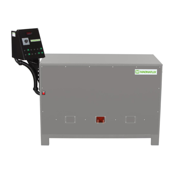
Related Manuals for Magnaflux CD-2000 Series


Summary of Contents for Magnaflux CD-2000 Series
- Page 1 CD-2000 SERIES CD-2000 Series Revised January 2020 Page | 1-0...
-
Page 2: Table Of Contents
Magnetization Current Check ....................4-4 SECTION 5 – TROUBLESHOOTING ..................... 5-1 Demagnetization Adjustment ....................5-1 Troubleshooting Guide ......................5-3 SECTION 6 – DRAWINGS & SPARE PARTS LIST ............... 6-1 SECTION 7 – HOOD INSTALLATION ................... 7-1 CD-2000 Series Revised January 2020 Page | 1-1... -
Page 3: General Safety Instructions
GENERAL SAFETY INSTRUCTIONS This manual provides information on how to install, operate, and maintain your Magnaflux magnetic particle inspection machine. Read these instructions carefully before operating or servicing your machine. • Only trained personnel should operate or service this machine. Be familiar with your facility and local procedures as well as Lock Out/Tag Out requirements before working with this machine. -
Page 4: Section 1: Equipment Specifications
“shot” is initiated. An ultraviolet black light causes the coated particles to glow, revealing flaws in the part being tested. Pertinent data (e.g., the unit’s serial number, electrical specifications, and duty cycle rating) may be found on the Magnaflux Data Plate, located on the end of the unit. EQUIPMENT SPECIFICATIONS CONVENIENCE OUTLETS... - Page 5 Reversing CD-2060 Contacts 6000 6000 Variable Decaying DC In all cases Continuously Reversing CD-2100 Contacts 10000 10000 Variable Decaying DC In all cases Continuously CD-2100HV Contacts 10000 10000 Variable In all cases CD-2000 Series Revised January 2020 Page | 1-4...
-
Page 6: Equipment Warranty
Basic Unit (No Hood) 70 in. (178 cm) Length 34.5 in.(88 cm) Depth 59 in.(150 cm) Height EQUIPMENT WARRANTY The Equipment Warranty Statement can be found on our Web site at the following link: https://www.magnaflux.com/Files/Corporate/Equipment-Warranty-Statement.pdf CD-2000 Series Revised January 2020 Page | 1-5... - Page 7 PAGE LEFT BLANK INTENTIONALLY CD-2000 Series Revised January 2020 Page | 1-6...
-
Page 8: Section 2: Installation And Storage
Consider the following requirements before selecting a permanent location for the inspection unit: 1. A power source of the proper voltage, frequency and phase (as designated on the Magnaflux Data Plate located on the end of the unit) capable of providing current per the nameplate. - Page 9 The inspection unit as supplied is internally wired for operation from a power source as designated on the Magnaflux Data Plate (located on the end of the unit). When connecting the unit all local codes should be followed. External wiring directions for operation on the designated voltage are as follows: 1.
- Page 10 High Voltage label. Table 2-2. Recommended Fuse Size CD-2060 Voltage Fuse Line Ground Wire wire Same as Line CD-2100 Voltage Fuse Line Ground Wire Wire Same as Line CD-2000 Series Revised January 2020 Page | 2-3...
- Page 11 With the screw turned all the way counter clockwise, that equals 0.5 seconds. If the screw is turned all the way clockwise, that equals 5 seconds. A shot timer (Magnaflux Accessory Part #622901) should be used to provide the actual shot time that has been set.
- Page 12 Not Applicable Item 13: Contacts Select Button Item 6: Not Applicable Item 14: Not Applicable Item 7: Coil Selection Button Item 15: Not Applicable Item 8: Not Applicable Item 16: Mag Button CD-2000 Series Revised January 2020 Page | 2-5...
-
Page 13: Preparation For Storage Or Shipment
Consolidated Freight Classification Rules that will insure safe transportation to the point of delivery. Estimated shipping dimensions and weight are listed in Tables 1-4 and 1-5. Mark the crate(s) clearly to identify the contents and denote which side is to be up. CD-2000 Series Revised January 2020 Page | 2-6... - Page 14 PAGE LEFT BLANK INTENTIONALLY CD-2000 Series Revised January 2020 Page | 2-7...
-
Page 15: Section 3: Operating Instructions
2. Allow black light to warn up for approximately 5 minutes. Check UV output of lamp using Magnaflux black light meter. Measure intensity at 15” from the lens, Clean lens or replace bulb if reading is less than 1000 microwatts/cm^2. -
Page 16: Piece Part Set-Up
If parts are hollow, tubular, ring-like, or have holes, it is generally better to magnetize them using a central conductor rather than passing current directly through them. This method also reveals defects on the inside diameter of the part. Circular Magnetization is accomplished by passing current through the central conductor. CD-2000 Series Revised January 2020 Page | 3-2... -
Page 17: Magnetizing Procedures
Tighten lock. 3. Press and release DEMAG push-button to start demagnetization cycle. DEMAG light will remain lit during complete cycle. 4. After demagnetization of part is complete, DEMAG light will go out. CD-2000 Series Revised January 2020 Page | 3-3... -
Page 18: Shutdown
2. Disconnect power from unit by turning external disconnect switch to OFF. SHUTDOWN EMERGENCY To shut off the machine in an emergency, disconnect the power by turning OFF the external disconnect switch. Lock Out unit as required. CD-2000 Series Revised January 2020 Page | 3-4... - Page 19 PAGE LEFT BLANK INTENTIONALLY CD-2000 Series Revised January 2020 Page | 3-5...
-
Page 20: Section 4: Maintenance
Report problems to the designated authority. Do not remove any cover panels. Inspections or maintenance requiring removal of cover panels are to be performed by a qualified technician. A list of Authorized Magnaflux Service Centers is located at www.magnaflux.com DAILY OPERATOR MAINTENANCE Table 4-1. -
Page 21: Monthly Operator Maintenance
Check transformers for discoloration and pungent order. Connections Check and tighten all connections, bus bars, cables and wires. Fans Check that the cooling fan(s) turn freely. Ammeter and “Mag” shot Check for accuracy every 6 months. time CD-2000 Series Revised January 2020 Page | 4-2... -
Page 22: Operational Checkout Procedures
Table 4-5. Test Equipment Recommended Test Equipment Tektronix TDS 20128 Two Channel Digital Storage Oscilloscope, 100 MHz, 1 GS/s Magnaflux 622350 Digital Test Meter Kit with Matching Shunt Steel Test Bar (1" diameter, 12"-18" long, 4140 H.T.) INITIAL SET-UP WARNING: Turn off and lock-out the external disconnect switch before opening the rear panel. -
Page 23: Magnetization Current Check
10. At the conclusion of the magnetization current check, proceed with the demagnetization check performing only those steps not previously accomplished. If no further testing is to be done, disconnect the digital test meter and return it to its carrying case. CD-2000 Series Revised January 2020 Page | 4-4... - Page 24 PAGE LEFT BLANK INTENTIONALLY CD-2000 Series Revised January 2020 Page | 4-5...
-
Page 25: Section 5: Troubleshooting
If there is no voltage across POT, check for 12VDC as follows: The 12VDC, +/-0.5V, should be connected to maximum 1POT, and wire #29 connected to minimum limit 4POT. If no voltage or low voltage, check for 12 volts across J3-6 to J3-8 of firing board. CD-2000 Series Revised January 2020 Page | 5-1... - Page 26 2. Check that control voltage (Wire 37 to Wire 29) decreases gradually over DEMAG cycle. If not, check Capacitor 1Cap. on subpanel. 3. If demag passes these steps, then re-do demag adjustment. CD-2000 Series Revised January 2020 Page | 5-2...
-
Page 27: Troubleshooting Guide
4. Check outputs on PLC and see if Output 6 is on during COIL mag shot and Output 7 is on during CONTACTS 4. Defective harnesses. shot. Check harnesses and replace or repair as necessary. 5. Defective SCRs. 5. Call Authorized Service Center CD-2000 Series Revised January 2020 Page | 5-3... - Page 28 2. Defective harness. 2. Check harnesses and repair/replace as necessary. Wrong voltage range 3. Adjust per instructions above on current controls 4. Shorted SCR. 4. Contact Authorized Magnaflux Service Center Current assurance Defective Ammeter Replace Ammeter light defective. Demag does not work 1.
- Page 29 1. Replace fuse 4FU. Check for shorts if fuse continues to blow. 2. Defective harness. 2. Check harnesses and replace or fix as necessary. 3. Meter failure from 3. Check cables for worn indication. Replace meter if surge. necessary. CD-2000 Series Revised January 2020 Page | 5-5...
- Page 30 PAGE LEFT BLANK INTENTIONALLY CD-2000 Series Revised January 2020 Page | 5-6...
-
Page 31: Section 6 - Drawings & Spare Parts List
PART NUMBER COLUMN On each drawing is a bill of material located in the lower right corner. Magnaflux part numbers are used to identify all parts except common commercial hardware. Commercial hardware is identified with a full identification in the DESCRIPTION column. - Page 32 SCR only for Rectifier Stack CD-2100 Part Number Description 521328 Relay 519940 Ammeter 519968 Fan only for Rectifier Stack 622996 Firing board only for Rectifier Stack 521095 SCR only for Rectifier Stack CD-2000 Series Revised January 2020 Page | 6-2...
- Page 33 PAGE LEFT BLANK INTENTIONALLY CD-2000 Series Revised January 2020 Page | 6-3...
-
Page 34: Section 7: Hood Installation
SECTION 7: HOOD INSTALLATION Not Applicable CD-2000 Series Revised January 2020 Page | 7-1... - Page 35 PAGE LEFT BLANK INTENTIONALLY CD-2000 Series Revised January 2020 Page | 7-2...
- Page 36 3624 West Lake Avenue, Glenview, Illinois 60026 USA Telephone: (847) 657-5300 Fax: (847) 657-5388 Web: www.magnaflux.com E-mail: cs@magnaflux.com CD-2000 Series Revised January 2020 Page | 7-3...
Need help?
Do you have a question about the CD-2000 Series and is the answer not in the manual?
Questions and answers