Advertisement
Quick Links
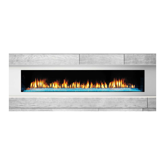
MODELS: PRIMO48, PRIMO48ST, PRIMO60, PRIMO60ST, PRIMO72, PRIMO72ST
Leave this manual with party responsible for use
and operation.
CAUTION! Risk of Cuts, Abrasions or Flying Debris.
Wear protective gloves and safety glasses during instal-
lation. Sheet metal edges are sharp.
This
appliance
comes
SafeSurface
Glass which keeps the surface temperature
TM
of the barrier glass at a safe level and will still be hot to
the touch when operated for long periods of time.
If the barrier glass is removed, the inner glass temperature
will be very hot and cause burns.
DANGER
DO NOT TOUCH GLASS
NEVER ALLOW CHILDREN
A barrier designed to reduce the risk of
burns from the hot viewing glass is provided
with this appliance and must be installed for
the protection of children and other at-risk
individuals.
WARNING! Risk of Fire! Combustible materials MUST
NOT overlap or be placed behind a decorative front.
CAUTION! Do not install damaged components.
WARNING! Risk of Fire! DO NOT apply combustible
materials beyond the minimum clearances. Comply with
all minimum clearances to combustibles as specified in
appliance installation manual.
HEAT-ZONE-PRIMO
Installation Instructions
standard
with
patented
HOT GLASS WILL
CAUSE BURNS.
UNTIL COOLED.
TO TOUCH GLASS.
Heat & Glo • HEAT-ZONE-PRIMO Instructions • 2310-936 Rev. J • 9/20
HEAT-ZONE-PRIMO
WARNING! Risk of Fire! Either the HEAT-ZONE-PRIMO
or the HEAT-OUT-PRIMO PowerFlow™ Heat Manage-
ment System must remain ON during operation of the ap-
pliance. Overheating will occur. Appliance will shut down.
Introduction
The HEAT-ZONE-PRIMO PowerFlow™ Heat Management
System conveys warm air from the fireplace through air
ducts to remote locations in the same room or other rooms
in the building. Two HEAT-ZONE-PRIMO's must be installed
with the PRIMO appliance or the appliance will overheat.
Two HEAT-ZONE-PRIMO's are included in the kit.
Note: A minimum clearance of 18 inches to any com-
bustible materials or combustible surfaces such as room
furnishings, furniture, curtains, etc., is required from the fan
housing air outlet. Plan for this clearance prior to installation
of the Heat-Zone-Primo kit. See Figure 6 and Figure 7.
Approvals
The flexible duct used with the HEAT-ZONE-PRIMO is
manufactured and marked to the requirements of UL-181,
Class I air duct.
Operation
The HEAT-ZONE-PRIMO PowerFlow™ Heat Management
System is powered by a thermo switch. The system will
turn on approximately 10 minutes after the appliance is
turned on. The HEAT-ZONE-PRIMO accessory is tested
and safe when installed in accordance with this installa-
tion manual. It is your responsibility to read all instructions
before starting installation and to follow these instructions
carefully during installation.
Installation of this kit MUST be performed by a qualified
service technician.
The HEAT-ZONE-PRIMO is carefully engineered and must
be installed only as specified. If you modify it or any of its
components you will void the warranty, and you may possibly
cause a fire hazard. Installation must be done according to
applicable local, state, provincial, and/or national codes.
1
Advertisement

Subscribe to Our Youtube Channel
Related Manuals for HEAT GLO HEAT-ZONE-PRIMO


Summary of Contents for HEAT GLO HEAT-ZONE-PRIMO
- Page 1 If you modify it or any of its components you will void the warranty, and you may possibly cause a fire hazard. Installation must be done according to applicable local, state, provincial, and/or national codes. Heat & Glo • HEAT-ZONE-PRIMO Instructions • 2310-936 Rev. J • 9/20...
- Page 2 STRAPS* CEILING REGISTER STRAPS* WALL REGISTER STRAP CEILING REGISTER WALL REGISTER WALL REGISTER Figure 1. HEAT-ZONE-PRIMO Locations Heat & Glo • HEAT-ZONE-PRIMO Instructions • 2310-936 Rev. J • 9/20...
-
Page 3: Preliminary Preparation
SILVER GROUND SCREW (Not a service Part) 695-125 REGISTER ADAPTER FRAME 659-150 WHITE REGISTER SCREWS 662-803 GEAR CLAMP: LARGE 659-129 DUCT ADAPTER: ROUND TO OVAL Figure 2. HEAT-ZONE-PRIMO Components Heat & Glo • HEAT-ZONE-PRIMO Instructions • 2310-936 Rev. J • 9/20... - Page 4 Figure 4. DO NOT SQUARE REMOVE VENT 6-3/4 in. KNOCKOUTS PIPE GASKET HEAT-OUT-PRIMO KNOCKOUTS MINIMUM SPACE 18 in. REQUIRED FOR 90 DEGREE BEND Figure 3. HEAT-ZONE-PRIMO Figure 5. Heat & Glo • HEAT-ZONE-PRIMO Instructions • 2310-936 Rev. J • 9/20...
- Page 5 FRONT OF FAN HOUSING 18 IN. MIN. (457 MM) CLEARANCE TO COMBUSTIBLE ROOM FURNISHINGS SUCH AS CURTAINS OR FURNITURE 14 IN. 4-1/2 IN. Figure 6. Wall Mounting (2 X 6) Heat & Glo • HEAT-ZONE-PRIMO Instructions • 2310-936 Rev. J • 9/20...
- Page 6 CSA C22.1. Screws Round to Oval Adapter Gear Clamp 6 in. Round Air Duct Gear Clamp JUNCTION BOX JUNCTION BOX FAN HOUSING FAN HOUSING Figure 9. Figure 8. Heat & Glo • HEAT-ZONE-PRIMO Instructions • 2310-936 Rev. J • 9/20...
- Page 7 VALVE COMPONENT TRAY Figure 10. Location of Rheostat in Control Cavity HEAT-ZONE-PRIMO Feature - Configuration HEAT-ZONE-PRIMO HEAT-ZONE-PRIMO HEAT-ZONE-PRIMO HEAT-ZONE-PRIMO Collar HEAT-ZONE-PRIMO Collar LED Color Switch Figure 11. HEAT-ZONE-PRIMO Configuration Heat & Glo • HEAT-ZONE-PRIMO Instructions • 2310-936 Rev. J • 9/20...
- Page 8 For the location of your nearest Heat & Glo dealer, please visit www.heatnglo.com. Heat & Glo, a brand of Hearth & Home Technologies 7571 215th Street West, Lakeville, MN 55044 www.heatnglo.com Heat & Glo • HEAT-ZONE-PRIMO Instructions • 2310-936 Rev. J • 9/20...
Need help?
Do you have a question about the HEAT-ZONE-PRIMO and is the answer not in the manual?
Questions and answers