Table of Contents
Advertisement
Quick Links
Advertisement
Table of Contents

Subscribe to Our Youtube Channel
Related Manuals for Logitek Remora


Summary of Contents for Logitek Remora
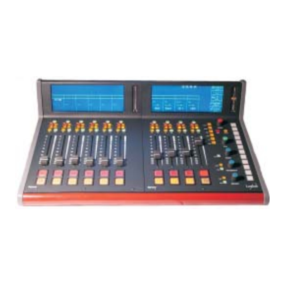
- Page 1 Logitek Remora Control Surface For the Digital Audio Engine Operations Manual...
- Page 2 Logitek Electronic Systems, Inc. Logitek is a trademark of Logitek Electronic Systems, Inc.
-
Page 3: Table Of Contents
Remora Specifications ....... 25 Remora Spare Parts Kit ....... 26... -
Page 4: Introduction
Logitek Digital Consoles represent a new concept for broadcast audio consoles. Logitek consoles centralize all audio mixing, routing, and distribution functions to one location in a facility. Once a Logitek system is in place, adding new inputs, outputs, or even new studios is very easy. -
Page 5: Unpacking
Remora Control Surface for Digital Audio Engine Unpacking Carefully unpack Audio Engine and control console cartons looking for any signs of shipping damage. You may wish to save the shipping cartons until operation of the system is verified and you are sure there is not hidden shipping damage. - Page 6 This page is deliberately blank.
-
Page 7: Installation
Remora Control Surface for Digital Audio Engine Installation The Remora control surfaces may be surface mounted on a table or cabinet. Connection of the Control Surface is easy and requires only two cables to the Power Supply Module. The connecting cable from the Power Supply to the Control Surface is supplied with a length of 10 feet (3 meters). - Page 8 Logitek in the length you need. Recommended wiring for this connection is Category 5 computer cable. Wiring to the control surface from power supply connects from DB-15 connector on one end (power supply end) to two cables with RJ-45 connectors on the other end.
- Page 9 Remora Control Surface for Digital Audio Engine The Remora Console control surface consists of two pieces, a top and a tray. To access the tray for secure mounting, remove the top by unscrewing the three screws along the back edge of the top panel and three screws along the front edge. Pull up on this edge and slide the panel backwards as it comes loose.
-
Page 10: Operation
Operation The Remora control surfaces are designed to be very familiar in look and feel to a traditional console yet with the power of the Audio Engine system easily accessible. Training time is much the same as for any other console. Many of the differences are seen in the configuration process and are not obvious to the operator. - Page 11 ON buttons when configuring the Audio Engine. The external controls require momentary closures. These attached functions will follow any change of inputs. Replacement buttons, lens caps and LEDs are available from Logitek. Part numbers are listed in the Appendix. Bus Assign buttons are momentary action and have status indicator LEDs.
- Page 12 The TB button can allow Talkback to individual sources as they are selected on a fader. When an input is selected with a mix-minus configured, pushing this button will direct the Talkback Mic audio source to the mix-minus output as long as the button is pressed.
- Page 13 Remora Control Surface for Digital Audio Engine The TRM Change button allows the adjustment of the relative gain level of the input. If the fader position is at an inconvenient point, adjust the gain up or down using the Select knob. The adjustment range is + and - 10 db.
-
Page 14: Monitor Controls
LCD display. Monitor Controls Three Monitor controls are provided on the Remora and are labeled HeadPhones, Monitor and Studio. The action of each is the same. A level control is present with each as well as a space on the LCD panel and a Change push button. - Page 15 Using the flexibility of the Logitek console, a solution would be to provide a separate post-processor input to the Audio Engine. This input could be used on the Phones monitor to give the processed feed to air talent without the extra delay.
- Page 16 Additional meter sets are located to the right of the LCD display in Figure 13 Remora VU Meters each fader section of the Remora. The other set is labeled Monitor and follows the choice made on the Monitor Control Selector. The meter LEDs are in a four color arrangement as follows: Green...
-
Page 17: Initial Power-Up
Library area of AEConfig. See the AEConfig manual for more information. Initial Power-Up The Remora will startup with all controls in a neutral position. If the surface is connected to the Audio Engine then the engine will reset all the switches and router assignments to the current values for the Control Surface port. - Page 18 To minimize the chance of program interruptions, use of an uninterruptible power supply (UPS) is recommended for the Audio Engine. The Remora Control Surfaces consume approximately 35 watts of power. Select a UPS size to provide the protection time you...
-
Page 19: Appendix
Appendix Control Surface Data Cable Category 5 LAN cable is recommended with a DB9 male at each end. 3 of the 4 twisted pair are used. Ports 1, 2 or 3 are used on the Communications Controller Card. The rear view of the male connector is shown. Pinout is the same at both ends. - Page 20 Port 3 no connect no connect pair 1 TX + pair 1 TX - pair 2 RX - pair 2 RX + no connect no connect enclosure ground...
-
Page 21: Control Surface Gpi
Appendix Control Surface GPI The Remora provides 12 analog input/tallyback connections along with 12 relay closures for external device control. The 12 device control relays are on a DB-25 connector, with the analog inputs on a second connector. The contacts of the internal relays are rated at 50 volts DC maximum and 500 milliamps maximum. - Page 22 Relay l A Relay l B Relay 2 A Relay 2 B Relay 3 A Relay 3 B Relay 4 A Relay 4 B Relay 5 A Relay 5 B Relay 6 A Relay 6 B Relay 7 A Relay 7 B Relay 8 A Relay 8 B Relay 9 A...
- Page 23 Appendix The analog inputs are activated by bringing the top row pin to ground on the bottom row. Connections are on a DB25 connector. The rear view is shown. GPI In l Ground GPI In 2 Ground GPI In 3 Ground GPI In 4 Ground...
-
Page 24: Power Module Control Surface Connection
Power Module Control Surface Connection Connection of the Control Surface to the Power Supply Module is made by a 15 pin D-Sub connector. The cable for this connection is DB-15 on the power supply end to two RJ-45 computer network type connectors on the Control Surface end. Cable 2 Pin 1 Cable 2 Pin 5 Cable 2 Pin 3... -
Page 25: Control Surface Connector
Appendix Control Surface Connector The two RJ-45 connectors on the control surface are represented here. Cable wiring will be according to the T568A color code. If T568B cables are used note that the positions of pairs 2 and 3 are exchanged. Carefully note order of pin connections in this list. Cable 1 JP17 RJ-45 Connection DB-15 Pin Connection... -
Page 26: Remora Specifications
Remora 16 - 32.5“ w x 13” d x 6” h (83 cm w x 33 cm d x 15 cm h), 30.5 lbs. (14 kg.) Remora 22 - 43“ w x 13” d x 6” h (109 cm w x 33 cm d x 15 cm h), 39.5 lbs. ( 18 kg.) Power Supply - 10“... -
Page 27: Remora Spare Parts Kit
Appendix Remora Spare Parts Kit Part number: Remora-SPARE Kit Contents • 2 each slide potentiometers • 1 each ON/OFF pushbutton switch • 3 each switches, Red, Yellow, and Green • 1 each Rotary encoder control ** Specifications are subject to change **... -
Page 29: Remora Installation Cross Section View
Appendix Remora Installation Cross Section View... - Page 30 LOGITEK authorized service centers freight prepaid with a description of the nature of the failure. No reimbursements can be made for repair charges that are not factory authorized. After repair or replacement, LOGITEK will return the equipment to the purchaser freight prepaid.
Need help?
Do you have a question about the Remora and is the answer not in the manual?
Questions and answers