Sign In
Upload
Download
Table of Contents
Contents
Add to my manuals
Delete from my manuals
Share
URL of this page:
HTML Link:
Bookmark this page
Add
Manual will be automatically added to "My Manuals"
Print this page
×
Bookmark added
×
Added to my manuals
Manuals
Brands
Gigabyte Manuals
Server
R162-Z10
User manual
Gigabyte R162-Z10 User Manual
Amd epyc 7003 server system - 1u 10-bay
Hide thumbs
1
2
3
4
5
Table Of Contents
6
7
8
9
10
11
12
13
14
15
16
17
18
19
20
21
22
23
24
25
26
27
28
29
30
31
32
33
34
35
36
37
38
39
40
41
42
43
44
45
46
47
48
49
50
51
52
53
54
55
56
57
58
59
60
61
62
63
64
65
66
67
68
69
70
71
72
73
74
75
76
77
78
79
80
81
82
83
84
85
86
87
88
89
90
91
92
93
94
95
96
97
98
99
100
101
102
103
104
105
106
107
108
109
110
111
112
113
114
115
116
117
118
119
120
121
122
123
124
125
126
127
128
129
130
131
132
133
134
135
136
137
138
139
140
141
142
143
144
145
146
147
page
of
147
Go
/
147
Contents
Table of Contents
Bookmarks
Table of Contents
Table of Contents
Chapter 1 Hardware Installation
Installation Precautions
Product Specifications
System Block Diagram
Chapter 2 System Appearance
Front View
Rear View
Front Panel LED and Buttons
Rear System LAN Leds
Power Supply Unit (PSU) LED
Hard Disk Drive Leds
Chapter 3 System Hardware Installation
Removing Chassis Cover
Removing and Installing the Fan Duct
Removing the Heat Sink
Installing the CPU
Installing the Memory
Eight Channel Memory Configuration
Installing the Memory
Processor and Memory Module Matrix Table
Memory Population Table
Installing the PCI Expansion Card
Installing the Mezzanine Card
Ocp 2.0
Installing the Hard Disk Drive
Installing the M.2 Device and Heat Sink
Replacing the Fan Assembly
Replacing the Power Supply
Cable Routing
Cable Routing for R162-Z10
Cable Routing for R162-Z11
Chapter 4 Motherboard Components
Motherboard Components
Jumper Setting
Chapter 5 BIOS Setup
The Main Menu
Advanced Menu
Trusted Computing
PSP Firmware Versions
Legacy Video Select
AST2500 Super IO Configuration
S5 RTC Wake Settings
Serial Port Console Redirection
CPU Configuration
PCI Subsystem Settings
USB Configuration
Network Stack Configuration
Nvme Configuration
SATA Configuration
UEFI POST LOGO Configuration
AMD Mem Configuration Status
T1S Auth Configuration
Intel(R) I350 Gigabit Network Connection
VLAN Configuration
MAC Ipv4 Network Configuration
MAC Ipv6 Network Configuration
AMD CBS Menu
CPU Common Options
DF Common Options
UMC Common Options
NBIO Common Options
FCH Common Options
NTB Common Options
SOC Miscellaneous Control
Workload Tuning
AMD PBS Menu
Ras
Chipset Setup Menu
North Bridge
Fabric Resource
Server Management Menu
System Event Log
View FRU Information
BMC Network Configuration
Ipv6 BMC Network Configuration
Security Menu
Secure Boot
Boot Menu
Save & Exit Menu
BIOS POST Beep Code (AMI Standard)
PEI Beep Codes
DXE Beep Codes
Advertisement
Quick Links
Download this manual
R162-Z10
R162-Z11
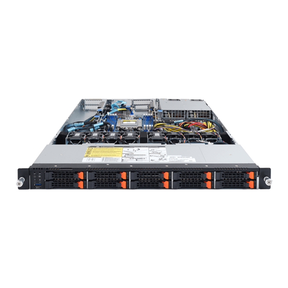
AMD EPYC™ 7003 Server System - 1U 10-Bay
User Manual
Rev. 1.0
Table of
Contents
Previous
Page
Next
Page
1
2
3
4
5
Advertisement
Table of Contents
Need help?
Do you have a question about the R162-Z10 and is the answer not in the manual?
Ask a question
Questions and answers
Related Manuals for Gigabyte R162-Z10
Server Gigabyte R162-Z11 User Manual
Amd epyc 7003 server system - 1u 10-bay (147 pages)
Server Gigabyte R162-ZA1 User Manual
Rack server (165 pages)
Server Gigabyte R162-ZA2 User Manual
Amd epyc 7003 up server system (143 pages)
Server Gigabyte R161-R13 Service Manual
1u intel x299 server system (35 pages)
Server Gigabyte R161-340 Service Manual
Dual sockets motherboard for intel scalable family processors (107 pages)
Server Gigabyte R161-R12 Service Manual
(123 pages)
Server Gigabyte R163-Z30-AAB1 User Manual
Amd epyc 9004 server system - 1u up 4-bay nvme/sata/sas (aab1), amd epyc 9004 server system - 1u up 4-bay sata/sas (aab2) (162 pages)
Server Gigabyte R163-S30-AAB1 User Manual
4th gen. intel xeon scalable server system - 1u up 4-bay nvme/sata/sas (aab1) 4th gen. intel xeon scalable server system - 1u up 4-bay sata/sas (aab2) (110 pages)
Server Gigabyte R163-Z32-AAH1 User Manual
Amd epyc 9004 server system - 1u dp 12-bay sata/sas (aag1), amd epyc 9004 server system - 1u up 12-bay nvme/sata/sas (aah1/aah2) (168 pages)
Server Gigabyte R163-Z35-AAC1 User Manual
Rack server - amd epyc 9004 - 1u up 12-bay gen5 nvme/sata/sas-4 (160 pages)
Server Gigabyte R164-SG0-AAH1 User Manual
Rack server - intel xeon 6 processors, 1u up 1 x pcie gen5 gpu (101 pages)
Server Gigabyte R163-P32-AAG1 User Manual
Rack arm server - ampereone family, 1u up 12-bay sata/sas-4 titanium aag1, 1u up 12-bay gen5 nvme/sata/sas-4 titanium aah1 (98 pages)
Server Gigabyte R164-AG0-AAV1 User Manual
Rack server - intel xeon 6 processors 1u up 1 x pcie gen5 gpu (104 pages)
Server Gigabyte R163-ZG2-AAJ2 User Manual
Rack server - amd epyc 9005/9004 1u up 1 x pcie gen5 gpu (163 pages)
Server Gigabyte R163-Z34-AAH1 User Manual
Rack server - amd epyc 9005/9004 - 1u up 4-bay gen5 nvme/sata/sas-4 (156 pages)
Server Gigabyte R164-SG5-AAV1 User Manual
Rack server - intel xeon 6 processors r1s - 1u up 1 x pcie gen5 gpu (107 pages)
This manual is also suitable for:
R162-z11
Table of Contents
Print
Rename the bookmark
Delete bookmark?
Delete from my manuals?
Login
Sign In
OR
Sign in with Facebook
Sign in with Google
Upload manual
Upload from disk
Upload from URL


Need help?
Do you have a question about the R162-Z10 and is the answer not in the manual?
Questions and answers