Table of Contents
Advertisement
Quick Links
Advertisement
Table of Contents

Summary of Contents for Perfecta Pro2
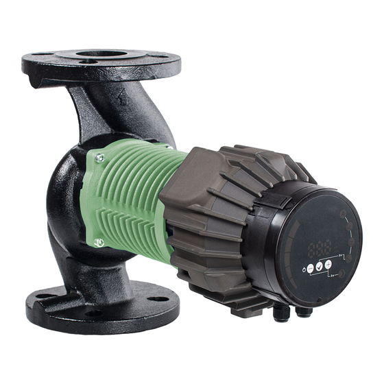
- Page 1 Pump Pro2 (D) Installation and operating manual...
- Page 2 EN: Compliance of the product with EU standards: Machinery directive (2006/42/EC). Standard used: EN 809; Low Voltage (2014/35/EU). Standard used: EN 60335–1; EN 60335-2-51; Electromagnetic compatibility (2014/30/EU). Standard used: EN 55014–1; EN 55014–2; EN 61000-3-2; EN 61000-3-3; ...
-
Page 3: Table Of Contents
English (EN) Installation and operating manual TABLE OF CONTENTS General information ..........................4 Uses ................................ 4 Pump labeling ............................4 Pump maintenance, spare parts and decommissioning ................. 4 Safety ..............................5 Tehnical specifications ........................5 Standards and protections ........................5 Pump medium ............................5 Temperatures and ambient humidity ..................... -
Page 4: General Information
GENERAL INFORMATION USES The Pro2 circulating pumps are used for the transfer of liquid medium within systems for hot-water heating, air-conditioning and ventilation. They are designed as single or twin variable-speed pumping aggregates where the speed is regulated by electronic device. The pump constantly measures pressure and flow and adjusts the speed according to the set pump mode. -
Page 5: Safety
Pro2 32F-10/12 PN6 and PN10 Pro2 (D)40–8/19 Pro2 40-10/12 Pro2 (D)40–12/24 Pro2 (D) 50–8/32 Pro2 50-10/12 Pro2 (D) 50–12/37 PUMP MEDIUM Pump medium can be pure water or a mixture of pure water and glycol, which is appropriate for central heating system. -
Page 6: Temperatures And Ambient Humidity
3.4.1 CURRENT, VOLTAGE AND POWER RATINGS Electrical ratings Rated Rated power Rated current Pump Rated voltage current Startup ) [A] Pro2(Z) xxx–6 0,75 0,75 230 VAC ± 15 %, Pro2(Z) xxx-10 47-63Hz Pro2(D) 40–80 Built-in Pumps operate at Pro2(D) 40–120... - Page 7 3.4.4 RELAY OUTPUT Electrical properties Rated current Maximum voltage 230 VAC, 32 VDC 3.4.5 ETHERNET Electrical properties Connector RJ-45, 10BASE-T, 10 Mbit/s. Web server (port 80) Services Software update through web interface. Option of Modbus RTU through TCP/IP Default IP address 192.168.0.245 (192.168.0.246 for right pump) LED1 Ethernet visual...
- Page 8 3.4.6 MODBUS Modbus specification Data protocol Modbus RTU Modbus connector Screwless terminals 2+1 pins. See communication manual. Modbus connection RS-485 type Modbus wire Two-wire + common Conductors: A, B and COM (Common). configuration See communication manual. Communication Integrated, 1/8 of Connect either via passive taps or daisy chain.
-
Page 9: Pump Installation
PUMP INSTALLATION INSTALLATION INTO PIPE LINES Pump is protected with a double box during transport. It can be lifted from the box with internal handles or by lifting it by the heat sink. Pumps are designed to be built in connecting flanges, using all screws. The connecting combined flanges are designed so the pump can be installed in PN6 or PN10 nominal pressure pipelines. -
Page 10: Electrical Installation
ELECTRICAL INSTALLATION The pump has a built-in over current fuse and protection, temperature protection and basic overvoltage protection. It doesn’t need an additional thermal protection switch. Connection leads should be capable of carrying rated power and should be properly fused. Ground lead connection is essential for safety. It should be connected first. -
Page 11: Setup And Operation
SETUP AND OPERATION CONTROL AND FUNCTIONS The pump can be controlled by display panel, 10-step switch, analog inputs, modbus or Ethernet connection. Display panel controls and overviews pump modes, parameters and on/off status, 10-step switch allows changing of relay output, analog inputs/outputs and resetting the pumps communication configuration, ... - Page 12 5.1.1 DISPLAY PANEL With the use of the display panel, you can control and overview pump modes, on/off control, pump parameters and errors. To see how pump modes work, see chapter 5.2 Operation. Bar graph display of pump parameters Numerical display of values Unit display Display of the currently selected mode Night mode...
- Page 13 Short press: Scrolling through parameters upwards when not changing parameter values, Scrolling through modes upwards when mode selection is selected, Changing parameters upwards when setting parameter values. Long press: 3 seconds together with puts us in night mode, ...
- Page 14 5.1.2 10-STEP SWITCH There is a mode selection rotary switch in the terminal box. It can be rotated by gently inserting a screwdriver into the arrow mark on top and rotating the switch to desired value. Switch setting is read when the pump turns on! More details about different modes can be found in communications manual.
- Page 15 5.1.3 ANALOG INPUT/OUTPUT The pump has three analog inputs/outputs with different functions. They can be configured through the web interface (page “pump”) or through Modbus. Input/Output Function Function description Turning the pump on/off. By default activating with connection to SET1 Run [Default - Mode 1] SET3.
- Page 16 5.1.7 RESETTING PUMP TO FACTORY SETTINGS For resetting the pump to factory settings all three buttons must be held for 5 seconds. This way the pump will set itself to automatic mode, delete previous height and power settings and unlock setting pump operation (if locked).
-
Page 17: Operation
OPERATION The pump can operate in 5 different modes. We can set the pump in the most appropriate mode, depending on the system where the pump operates. The pump modes: Automatic mode (factory default), Proportional pressure, Constant pressure, ... - Page 18 5.2.1 TWIN PUMP OPERATION Twin pump has double hydraulic housing with integrated check valve, which automaticly turns based on medium flow, and two separated motors. Pumps communicate with each other through Ethernet connection. Night mode is not recommended in this mode of operation. Pumps can operate in several different modes, switching betweend the pumps is done by the communications module: Alternating operation [default setting] –...
-
Page 19: Error And Troubleshooting
ERROR AND TROUBLESHOOTING If pump failure occurs, the error causing the failure will appear in the display screen. Errors on the screen are identified as: E X Y Error marking Error group Service code Error group Error description Possible cause and solution Low load detected There is no medium in the pump. - Page 20 Error code Description Probable cause Load errors E10 (drY) Low motor load Low load detected. Pump is running dry. Motor might be faulty or viscous medium is High motor load present. Protection active Circuit is too hot and power was reduced to E22 (hot) Converter temperature limit less than 2/3 of rated power.
-
Page 21: Images
IMAGES...
Need help?
Do you have a question about the Pro2 and is the answer not in the manual?
Questions and answers