Table of Contents
Advertisement
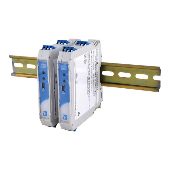
USB Programmable, DIN Rail Mount,
Passive I/O DC Current/Voltage Input Splitter with
Dual Isolated 2-Wire 4-20mA Transmitter Outputs
Model SP236-0600, DC Current & Low DC Voltage Input
Model SP237-0600, DC ±1V/±10V Medium Voltage Input
Model SP238-0600, DC ±15V/±150V High Voltage Input
USER'S MANUAL
ACROMAG INCORPORATED
Tel: (248) 295-0880
30765 South Wixom Road
Fax: (248) 624-9234
Wixom, MI 48393-2417 U.S.A.
email: sales@acromag.com
Copyright 2018, Acromag, Inc., Printed in the USA.
8501105B
Data and specifications are subject to change without notice.
Advertisement
Table of Contents

Subscribe to Our Youtube Channel
Related Manuals for Acromag SP236-0600

Summary of Contents for Acromag SP236-0600
- Page 1 USB Programmable, DIN Rail Mount, Passive I/O DC Current/Voltage Input Splitter with Dual Isolated 2-Wire 4-20mA Transmitter Outputs Model SP236-0600, DC Current & Low DC Voltage Input Model SP237-0600, DC ±1V/±10V Medium Voltage Input Model SP238-0600, DC ±15V/±150V High Voltage Input USER’S MANUAL...
-
Page 2: Table Of Contents
BLOCK DIAGRAM ..................... 28 How It Works ........................28 TROUBLESHOOTING ..................29 Diagnostics Table ....................... 29 Service & Repair Assistance ....................31 ACCESSORIES ....................32 Software Interface Package ....................32 Acromag, Inc. Tel: 248-295-0880 - 2 - - 2 - https://www.acromag.com http://www.acromag.com... - Page 3 This is very important where property loss or human life is involved. It is important that you perform satisfactory overall system design and it is agreed between you and Acromag, that this is your responsibility.
-
Page 4: Getting Started
2-wire current loops proportional to the input. Means “Refer to User’s Manual The SP236-0600 is designed for DC Current (0-20mA/4-20mA), and Low Voltage DC (this manual) for additional (±0.5V/0-500mV) input. The SP237-0600 is designed for medium voltage DC signals information”... -
Page 5: Application
75VDC or 50VAC. Acromag, Inc. Tel: 248-295-0880 - 5 - - 5 - https://www.acromag.com http://www.acromag.com... -
Page 6: Din Rail Mounting & Removal
DIN rail clip and use it as a lever to force the DIN rail spring clip down while pulling the bottom of the module outward until it disengages from the rail. Then simply lift it from the rail. Acromag, Inc. Tel: 248-295-0880 - 6 - - 6 - https://www.acromag.com... -
Page 7: Electrical Connections
Important – End Stops: For hazardous location installations (Class I, Division 2 or ATEX / IECEx Zone 2), it should utilize two end stops (like Acromag 1027-222) to help secure modules to the DIN rail (not shown). - Page 8 Model SP23x-0600 Two-Wire DC I/V Dual Output Transmitters w/USB Acromag, Inc. Tel: 248-295-0880 - 8 - - 8 - https://www.acromag.com http://www.acromag.com...
-
Page 9: Output/Power Connections
Earth ground is normally applied at the loop power supply minus terminal. Each 2-wire transmitter output varies off this ground by the voltage drop in the load resistance and lead-wire of the loop. Acromag, Inc. Tel: 248-295-0880 - 9 - - 9 - https://www.acromag.com... - Page 10 Other receivers that do not provide loop excitation are referred to as “sinking” inputs, and these will require that a separate power supply connect within the loop. These types of receivers are depicted in the figures on the next two pages Acromag, Inc. Tel: 248-295-0880 - 10 - - 10 - https://www.acromag.com...
- Page 11 (such as an I/P current-to-pressure transducer), this may reduce output stability. In this case, place a 0.1uF capacitor directly across the inductive load(s) and this will typically cure the problem. Acromag, Inc. Tel: 248-295-0880 - 11 - - 11 - https://www.acromag.com...
-
Page 12: Earth Ground Connections
Respect the traditional position of earth ground in a two-wire current loop and avoid inadvertent connections to earth ground at other points in the same loop, which would drive ground loops and negatively affect operation. Acromag, Inc. Tel: 248-295-0880 - 12 - - 12 - https://www.acromag.com... -
Page 13: Usb Connections
USB connection (See Output/Power Connections). • USB Signal Isolation is Required (See Below) - You may use Acromag model USB-ISOLATOR to isolate your USB port, or you can optionally use another USB signal isolator that supports USB Full Speed operation (12Mbps). -
Page 14: Configuration Software
“Wiring Diagram”. You may swipe left or right to view more diagrams. The main screen also has three icons across the top: an Acromag logo w/connected model indicated, a question mark, a gear icon, and three vertical dots. These icons access additional features of this software as... - Page 15 Video Tutorial URL line. Or, if you wish to contact Acromag for assistance, you can tap the [CONTACT ACROMAG] bar to obtain the phone and email information window shown below for talking to Acromag directly (the same information is also obtained via the menu dotted action bar icon and “Contact Acromag”...
- Page 16 If you tap the right-most dotted Menu icon of the action bar at the top right of your screen, you will get a selection menu for “About” information on this software application, and “Contact Acromag” for contact information, both shown at left Below the icons of the top line are file three tabs: Configuration, Calibration, and Diagnostic Center, each of which are described in the following pages.
- Page 17 ADC level to its input range full-scale (100%). The device status at the bottom of the page will report if the calibration was sent successfully. Acromag, Inc. Tel: 248-295-0880 - 17 - - 17 - https://www.acromag.com...
- Page 18 When rescaling I/O, make sure that you have adequate I/O span, as “too-tight” input or output spans will have diminished resolution and magnify error. Acromag, Inc. Tel: 248-295-0880 - 18 - - 18 - https://www.acromag.com...
- Page 19 Check the “Save Data” box if you wish to log the polled values to a CSV (Comma Separated Value) data file for reference. Note the Communication Status of the device is indicated at the bottom of the screen. Acromag, Inc. Tel: 248-295-0880 - 19 - - 19 - https://www.acromag.com...
-
Page 20: Quick Overview - Windows
Software and a USB connection to a Windows PC or laptop. The configuration software can be downloaded free of charge from our web site at www.acromag.com. This software is also included on a CDROM bundled with the Configuration Kit TT-SIP (see Accessories section). - Page 21 Calibration Status (Bottom of Screen) • Displays communication status messages for the calibration process. The CALIBRATION STATUS field at the bottom of the screen will display status messages relative to calibration. Acromag, Inc. Tel: 248-295-0880 - 21 - - 21 - https://www.acromag.com http://www.acromag.com...
-
Page 22: Operation Step-By-Step
SP237Config.exe, or SP238Config.exe software per your splitter model to begin configuration of your unit (this software is compatible with Windows 7 or later versions of the Windows operating system), or start the Agility mobile app (Android only). Acromag, Inc. Tel: 248-295-0880 - 22 - - 22 - https://www.acromag.com... -
Page 23: Configuration
Two-Wire DC I/V Dual Output Transmitters w/USB Configuration After executing the Acromag Configuration software for your model, a screen like that shown at left will appear if you have not already connected to your transmitter via USB (note fields are blank and red status message appears). - Page 24 [Send I/O Config], or by save it to a file by clicking “File” in the upper left-hand corner of the screen. Acromag, Inc. Tel: 248-295-0880 - 24 - - 24 - https://www.acromag.com...
- Page 25 Note the simulated lamp next to the button flashes slowly each time it samples the input. Click the [Stop Polling] button to stop polling the input channel before moving onto the next page. Acromag, Inc. Tel: 248-295-0880 - 25 - - 25 - https://www.acromag.com...
-
Page 26: Calibration (Optional)
Once you input full-scale precisely, click the [OK] button of the prompt to calibrate full-scale and then follow the on-screen prompt. Acromag, Inc. Tel: 248-295-0880 - 26 - - 26 - https://www.acromag.com... - Page 27 This field displays calibration status messages like “No Error”, “Transfer Error”, and “Timeout Error” during calibration. If you encounter a Transfer or Timeout Error, you should repeat the calibration process. Acromag, Inc. Tel: 248-295-0880 - 27 - - 27 - https://www.acromag.com...
-
Page 28: Block Diagram
PC earth ground and a grounded input sensor, which would but not the output. have the negative effect of pulling the input bias supply to ground, clipping the negative portion of the bipolar input range. Acromag, Inc. Tel: 248-295-0880 - 28 - - 28 - https://www.acromag.com... -
Page 29: Troubleshooting
Verify that power is applied to the USB has not enumerated the Use the reset button on the Acromag USB loop and that your loop power device. isolator to trigger renumeration of the... - Page 30 Acromag, Inc. Tel: 248-295-0880 - 30 - - 30 - https://www.acromag.com http://www.acromag.com...
-
Page 31: Service & Repair Assistance
Thus, it is highly recommended that a non- functioning transmitter be returned to Acromag for repair or replacement. Acromag has automated test equipment that thoroughly checks and calibrates the performance of each transmitter, and can restore firmware. Please refer to the Acromag Service Policy and Warranty Bulletins, or contact Acromag for complete details on how to obtain repair or replacement. -
Page 32: Accessories
This is a 1 meter, USB A-miniB replacement cable for connection between the USB isolator and the TT/SP transmitter/splitter. It is normally included in TT-SIP. Note that software for all TT/SP Series models is available free of charge, online at www.acromag.com. Acromag, Inc. Tel: 248-295-0880 - 32 - - 32 - https://www.acromag.com... -
Page 33: Accessories
Cable and an Android mobile phone or tablet that support USB. It is required to use the Acromag Agility™ Config Tool App for Android OS reconfiguration of this splitter. Note that the Acromag Agility ™ Config Tool is available free of charge, online at the Google Play store. -
Page 34: Specifications
An optional external sensor is required to monitor AC current signals for driving TB1 of the SP236 (see Acromag Model 5020-350). This toroidal sensor generates 0 to 11.17mA DC to drive the DC current input of this module with AC input current through its primary (see Table 2 of page for scaling the AC current by number of primary turns). - Page 35 22265 to 43271 or 1/21006 0-150V DC (TB2) 5.36K/1003.36K 32768 to 53774 or 1/21006 0 to 75V DC (TB2) 5.36K/1003.36K 32768 to 43271 or 1/10503 Note: AD_count = (Vin*Gain/1.25) * 32768+32768. Acromag, Inc. Tel: 248-295-0880 - 35 - - 35 - https://www.acromag.com http://www.acromag.com...
- Page 36 DC current input at TB1. AC Input Burden: A function of the wire gauge resistance used for primary turns (the current carrying wire being monitored). Acromag, Inc. Tel: 248-295-0880 - 36 - - 36 - https://www.acromag.com...
-
Page 37: Input
(SP236 models optionally support AC input current at TB1 when wired for use with Acromag AC Current Sensor 5020-350). Output Accuracy: Accuracy is typically better than 0.05% of span (0.1% Max) for nominal input ranges. -
Page 38: Usb Interface
USB 2.0 compatible. Transient Protection: Adds transient voltage protection on USB power & data lines. Inrush Current Limiting: Includes series inrush current limiting at USB power. Cable Length/Connection Distance: 5.0meters maximum. Acromag, Inc. Tel: 248-295-0880 - 38 - - 38 - https://www.acromag.com... -
Page 39: Enclosure & Physical
OFF is normal, blinks for fault, or blinks once if the loop power is lost or the loop is opened. Acromag, Inc. Tel: 248-295-0880 - 39 - - 39 - https://www.acromag.com... -
Page 40: Environmental
1) Enclosure Port, per CISPR 16. 2) Low Voltage AC Mains Port, per CISPR 14, 16. 3) DC Power Port, per CISPR 16. Telecom / Network Port, per CISPR 22. Acromag, Inc. Tel: 248-295-0880 - 40 - - 40 - https://www.acromag.com... -
Page 41: Agency Approvals
EN/IEC 60079-15 3) Transient protection should be provided set to a level not exceeding 140% of the peak rated voltage value at the supply terminals to the equipment. Acromag, Inc. Tel: 248-295-0880 - 41 - - 41 - https://www.acromag.com... -
Page 42: Reliability Prediction
The following table shows the revision history for this document: Release Date Version EGR/DOC Description of Revision 16 FEB 2018 BC/MO Initial Release Version. 27 NOV 2018 CAP/ARP Added UL / ATEX / IECEx / FCC statements. Acromag, Inc. Tel: 248-295-0880 - 42 - - 42 - https://www.acromag.com http://www.acromag.com...
Need help?
Do you have a question about the SP236-0600 and is the answer not in the manual?
Questions and answers