
Related Manuals for ELTEX R130A


Summary of Contents for ELTEX R130A
- Page 1 Operating Instructions R130A / R131A Charging Bar EXR130A Charging Bar BA-en-3020-2101...
- Page 2 BA-en-3020-2101_R130A / R130A3L / R131A / EXR130A / EXR130A3L...
-
Page 3: Table Of Contents
Overview charging bars....... . 6 1.1 R130A / R131A / EXR130A charging bars ....6 1.2 R130A3L / EXR130A3L charging bars . - Page 4 BA-en-3020-2101_R130A / R130A3L / R131A / EXR130A / EXR130A3L...
- Page 5 Dear customer The R130A / R130A3L / R131A / EXR130A / EXR130A3L charging bar is a universal bar for charging surfaces for the purpose of tacking, adhering or locking. The variable active lengths of the charging bars allow them to be adapted to your specific in-process conditions and requirements.
-
Page 6: Overview Charging Bars
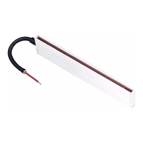
The parallel configuration of two or more bars allows surface-covering charging or operating the unit at high web speeds. The maximum total length of the charging bar is 3985 mm. 1.1 R130A / R131A / EXR130A charging bars View X 0...360° (max. 1 revolution) Fig. -
Page 7: R130A3L / Exr130A3L Charging Bars
The connection of the high voltage cable is detachable and only available axial to the bar. 1.2 R130A3L / EXR130A3L charging bars Fig. 2: R130A3L / EXR130A3L charging bars R130A3L / EXR130A3L bar Same bar as R130A / EXR130A,but with air connection. BA-en-3020-2101_R130A / R130A3L / R131A / EXR130A / EXR130A3L... -
Page 8: Safety
2.1 Proper Use The charging bars of the series R130A / R130A3L / R131A / EXR130A / EXR130A3L must only be used for applying static electrical charges onto paper, fabrics, foils, plastics, etc. for the purpose of creating a static adhe- sion effect. -
Page 9: Work And Operational Safety
2.3 Work and operational safety Warning! Electric shock hazard! Carefully observe the following notes and the complete chapter 2 "Safety”, page • Before carrying out repairs, cleaning or maintenance work and before resetting the unit after malfunctions, switch off the power supply and disconnect the supply voltage (see chapter 5 "Maintenance”, page chapter 7 "Troubleshooting”, page... - Page 10 The minimum operating current for any stable-cur- rent working point must be >0.5 mA (see chapter 4.1 "Operating voltage for the R130A / R130A3L / R131A / EXR130A / EXR130A3L charging bars”, page chapter 4.2 "Operating modes”, page 20).
-
Page 11: Contact Protection
2.4 Contact protection The site of installation and/or use of the units is outside the control of Eltex, contact protection against inadvertent contact of the bars and of live components by personnel as specified by the employer’s liability insu- rance association may have to be provided (e.g. DGUV V3 in Germany). -
Page 12: Installation And Assembly
3. Installation and assembly 3.1 Length of the charging bar Depending on intended use, the total length of the charging bar may be selected within the range from 85 mm to 3,985 mm in steps of 20 mm each. The total length is made up of active length plus 70 mm. For operating voltages >30 kV add 120 mm or 220 mm instead of 70 mm (see Fig. - Page 13 The installation may also be carried out using fitting material supplied by Eltex. The material consists of two insulators with GRP base plate plus four sliding nuts with bolts. The insulators maintain the 150 mm creepage distance.
- Page 14 Fig. 5: Installation > 2 0 0 example using Eltex fitting material 1 Bar 2 Eltex fitting material 3 Machine wall Fig. 6: Installation example using Eltex fitting material, charging a foil against earth with positive high voltage Possible applications. tacking protective foil, laminating decorative mate- rial etc.
- Page 15 Install the bar such that no creepage currents develop through the bars and the attachment fittings during subsequent operation. Creepage cur- rents can cause irreparable damage to the bar and the attachment fittings. Minimum installation distances: • No conductive material to be fitted at a distance of 40 mm around the charging bar •...
- Page 16 The installation profile of the charging bar has 3 flutings. Any of these three flutings may be used for installation. The sliding nuts are pushed into these flutings, and the charging bar is bolted to these sliding nuts. Caution! Observe the bolt depth! M 5 ( 3 Fig.
-
Page 17: Connecting The High Voltage Cable To The Generators Knh18, Knh34 / Knh35, Knh64 / Knh65, To The Distributor Box Knhv3 / Knhv6 And To The Charging Bar R131A
3.5 Connecting the high voltage cable to the generators KNH18, KNH34 / KNH35, KNH64 / KNH65, to the distributor box KNHV3 / KNHV6 and to the charging bar R131A The connection of the high voltage cable of the charging bar with max. 25 kV, max, 30 kV and max. -
Page 18: Connecting The High Voltage Cable Of The Charging Bar To The High Voltage Generator Power Charger Pc
3.6 Connecting the high voltage cable of the charging bar to the high voltage generator POWER CHARGER PC_ _ Warning! Electric shock hazard! Work may be carried out only if: • the supply voltage to the generator has been disconnected, •... -
Page 19: Disconnecting The High Voltage Cable
3.7 Disconnecting the high voltage cable Warning! Electric shock hazard! Work may be carried out only if: • the supply voltage to the generator has been disconnected, • the machine is at a standstill because the bars pick up charges if the material web is running. -
Page 20: Operation
4. Operation 4.1 Operating voltage for the R130A / R130A3L / R131A / EXR130A / EXR130A3L charging bars R130A, R130A3L, R131A charging bars: 10…30 kV DC EXR130A, EXR130A3L charging bars: max. 30 kV DC / +20 kV DC – Make sure that the correct distance between the charging bar and the material surface is maintained. -
Page 21: Maintenance
5. Maintenance Warning! Electric shock hazard! • Do not carry out any maintenance or repair work without first switching off the high voltage generator and disconnecting the supply voltage. • The bars passively absorb energy from the moving substrate web. The high voltage cable must be plugged in or grounded to the power supply. -
Page 22: Warranty
The warranty applies only if the operating and assembly instructions spe- cified by Eltex have been observed. The warranty period begins on the date of delivery. In the event of defects occurring during the warranty period, the units or defective components will be repaired at Eltex. -
Page 23: Troubleshooting
7. Troubleshooting Warning! Electric shock hazard! • Do not carry out any maintenance or repair work without first switching off the high voltage generator and disconnecting the supply voltage. • The machine which has the units fitted must not be in operation. •... -
Page 24: Technical Specifications
8. Technical specifications R130A / R130A3L / R131A Bar element glass-fibre-reinforced synthetic GRP Encapsulating compound Emission tips special alloy Ambient operating temperature 0...+60°C (+32...+140°F) Ambient humidity max. 60 % relative humidity non-dewing Operating voltage max. 30 kV DC (R130A3 / R130A3L / R131A3) max. - Page 25 -30 kV DC / +20 kV DC Operating current typically 1 mA per meter of active bar length High voltage power via Eltex high voltage generators series HSG61 supply and POWER CHARGER PC_ _ High voltage cable prefabricated high voltage cable in plastic tube with plug for the high voltage generator, length 1...99 m (standard length 5 m)
-
Page 26: Dimensions
9. Dimensions View X Ø 2 0 Ø 1 3 Fig. 13: Dimensions of the charging bar Examples for calculating the active length n = any number between 1 and 196, e.g. n = 150 The active length is therefore AL = 150 x 20 - 5 = 2995 mm AL = Active length GL = Total length EL = Installation length... -
Page 27: Spare Parts And Accessories
100876 Bolt synthetic M5x25 KSR00015 Bar bracket with clamp HA01/__ Bar bracket with aluminium profile section HA06/__ Eltex installation kit (insulators, GRP base plate, sliding nuts, bolts) BMO08613 Insulators MCH02147 Mounting material for bars: sliding nut with screws and washers... - Page 28 Article Article number Plug X Kit for cutting the high voltage cable to size with flexible tube for 60 kV charging bars for connection of the generator POWER CHARGER PC_ _ (external diameter of the cable min. 6.55 mm) resp. modification set for charging plug X, high voltage cable Bedea, KWV, Sumitomo 117400...
-
Page 29: Annex
A. ANNEX A.1 Quick plug-in connection for charging components for plug variants M (only in connection with the generators KNH18, KNH34, KNH35) Warning! Connect only to the generator side! Make sure that no high voltage applies at the end of the cable after disconnecting the plug! Before connecting or disconnecting the plug, deactivate the supply vol- tage of the high voltage generator manually. - Page 32 Eltex offices and agencies The addresses of all Eltex agencies can be found on our website at www.eltex.de Eltex-Elektrostatik-Gesellschaft mbH Blauenstraße 67-69 79576 Weil am Rhein | Germany Phone +49 (0) 7621 7905-422 eMail info@eltex.de Internet www.eltex.de...
Need help?
Do you have a question about the R130A and is the answer not in the manual?
Questions and answers