Advertisement
Quick Links
Advertisement

Related Manuals for USA Technologies ePort G9


Summary of Contents for USA Technologies ePort G9
- Page 1 Installing the USAT G9...
- Page 2 ePort Serial number and Customer Service phone number are on every box...
-
Page 3: What's In The Kit
What’s in the kit... - Page 4 What’s in the kit...
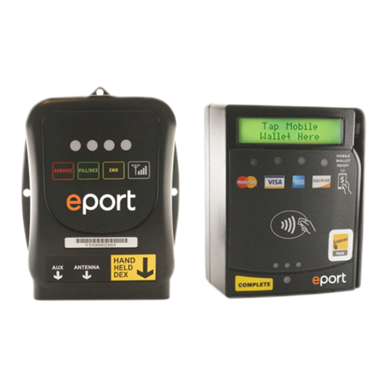
- Page 5 G9 Controller and cable connectors...
- Page 6 Aux, Antenna and DEX receptacles...
- Page 7 Standard antenna and connector...
- Page 8 Card Reader mounting screw holes, cable and connector...
- Page 9 Choose a suitable location to mount the G9 Controller • Carefully choose a location inside the vendor door or cabinet to mount the G9 Controller. Make sure the G9 MDB, DEX and Serial cables will be able to reach their connection points to the vendor MDB cables, DEX port and the Card Reader cable.
- Page 10 Power down the machine and Locate the MDB Bus connectors between the machine controller and bill acceptor. Then separate the connectors.
- Page 11 Connect to the MDB bus with the two 6 position connectors of the G9 MDB cable...
- Page 12 Antenna connection to G9 Controller...
- Page 13 Card Reader cable connection to G9 Controller...
- Page 14 to VMC Connection NOTE: The vendor DEX port will be found in different locations according to vendor make/model. Look for the standard female phono type receptacle.
- Page 15 The card reader can be installed with a spacer or without depending on the vendor. Be sure to use the short screws for mounting without the spacer. The long screws are for use only with a spacer. Short screws supplied Long screws come in hardware bag attached with spacer...
- Page 16 Card reader mounted in second cutout...
- Page 17 Inside view of Card Reader with flange plate...
- Page 18 Surface mounted Card Reader using drilling template. Temporarily remove bill acceptor before drilling holes . Reinstall after mounting Card Reader...
- Page 19 Start up / LED activity and reader displays First card reader display Green LED will light and then flash...
- Page 20 Start up / LED activity and reader displays continued Device serial number and firmware rev Blue and Green LEDs will blink displayed on reader.
- Page 21 Start up / LED activity and reader displays continued Blue and Green LEDs will blink MEID and IP Address displayed...
- Page 22 Swipe A Card. Unit is ready for business G9 - Green LED Blinking Welcome Card Reader Message...
- Page 23 Authorizing a card Authorizing Card is approved - ready to vend...
- Page 24 User is prompted through the vend process...
- Page 25 In multi-vend mode the customer is asked to make another selection or press “END” Once the END (Complete) button is pressed, the purchased items are totaled...
- Page 26 Thank You Message is displayed...
- Page 27 Push this button to perform Signal Test Numeric signal strength reading will display on card LEDs will light according to signal strength. See next reader slide for LED Chart.
- Page 28 RSSI (CSQ) LED Chart...
- Page 29 AMS Vendors Card reader opening Bill acceptor opening...
- Page 30 National Merchant Card reader is inserted in POS window. Card reader kit # 1815084 is available from Crane to mount the reader...
- Page 31 HVV Vendor & DN5800 with optional install kits HVV card reader kit DN5800 Card Reader kit Pepsi HVV Dixie 5800...
- Page 32 High gain antenna mounting on DN5800 You will need to trim the metal lip above the door to provide clearance for the antenna...
- Page 33 Royal 500 with Card Reader Kit & High Gain Antenna...
- Page 34 G9 LED MATRIX for basic troubleshooting = Blinking x2 = number of blinks = On solid...
Need help?
Do you have a question about the ePort G9 and is the answer not in the manual?
Questions and answers