Table of Contents
Advertisement
Quick Links
The Netherlands B.V.
John M. Keynesplein 9
OSHA 1926.502
A
A
1
8530886
2
8530887
3
8530888
4
8530889
5
8530920
6
8530921
EN 795:2012
Type E
CEN/TS 16415:2013
Type E
Regulation (EU) 2016/425
CE Type Test
CE Production Quality Control
No. 2797
No. 2797
BSI
The Netherlands B.V.
Say Building
Say Building
John M. Keynesplein 9
1066 EP
1066 EP
Amsterdam
Amsterdam
Netherlands
Netherlands
OSHA 1910.140
B
3
1
2
3M
TM
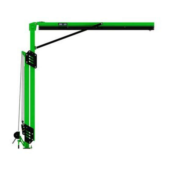
Modular Jib System M200
Adjustable Jib Boom
USER INSTRUCTIONS
BSI
1
W
15.0 ft.
1
8530891
(4.6 m)
15.0 ft.
1
8530892
(4.6 m)
15.0 ft.
1
8530893
(4.6 m)
15.0 ft.
1
8530894
(4.6 m)
12.0 ft.
1
8530895
(3.7 m)
12.0 ft.
1
8530896
(3.7 m)
12.0 ft.
1
8530897
(3.7 m)
12.0 ft.
1
8530898
(3.7 m)
15.0 ft.
2
8530899
(4.6 m)
15.0 ft.
2
8530900
(4.6 m)
15.0 ft.
2
8530901
(4.6 m)
12.0 ft.
2
8530902
(3.7 m)
12.0 ft.
2
8530903
(3.7 m)
12.0 ft.
2
8530904
(3.7 m)
W
1
A
4
5
DBI-SALA
Flexiguard
®
5908372 Rev. C
€
H
lb. (kg)
12.3 ft. - 15.0 ft.
945 lb.
(3.8 m - 4.6 m)
(429 kg)
14.8 ft. - 20.0 ft.
1,057 lb.
(4.5 m - 6.1 m)
(479 kg)
17.3 ft. - 25.0 ft.
1,169 lb.
(5.3 m - 7.6 m)
(530 kg)
19.8 ft. - 30.0 ft.
1,281 lb.
(6.0 m - 9.1 m)
(581 kg)
12.3 ft. - 15.0 ft.
1,011 lb.
(3.8 m - 4.6 m)
(459 kg)
14.8 ft. - 20.0 ft.
1,123 lb.
(4.5 m - 6.1 m)
(509 kg)
17.3 ft. - 25.0 ft.
1,235 lb.
(5.3 m - 7.6 m)
(560 kg)
19.8 ft. - 30.0 ft.
1,343 lb.
(6.0 m - 9.1 m)
(609 kg)
15.0 ft. - 20.0 ft.
818 lb.
(4.6 m - 6.1 m)
(371 kg)
20.0 ft. - 25.0 ft.
930 lb.
(6.1 m - 7.6 m)
(422 kg)
25.0 ft. - 30.0 ft.
1,041 lb.
(7.6 m - 9.1 m)
(472 kg)
15.0 ft. - 20.0 ft.
850 lb.
(4.6 m - 6.1 m)
(386 kg)
20.0 ft. - 25.0 ft.
961 lb.
(6.1 m - 7.6 m)
(436 kg)
25.0 ft. - 30.0 ft.
1,073 lb.
(7.6 m - 9.1 m)
(487 kg)
W
H
H
2
A
6
C
8530912
TM
€
x1
x2
© 3M 2020
Advertisement
Table of Contents

Subscribe to Our Youtube Channel
Related Manuals for DBI SALA 3M Flexiguard M200

Summary of Contents for DBI SALA 3M Flexiguard M200
- Page 1 EN 795:2012 DBI-SALA Flexiguard ® Type E Modular Jib System M200 CEN/TS 16415:2013 Type E Adjustable Jib Boom Regulation (EU) 2016/425 CE Type Test CE Production Quality Control No. 2797 No. 2797 USER INSTRUCTIONS The Netherlands B.V. The Netherlands B.V. Say Building Say Building John M.
- Page 4 = 360° = 0°...
- Page 9 2797 EN795:2012 "TYPE E" CEN/TS 16415:2013 "TYPE E" OSHA 1926.502 & 1910.140 ≤ 6 kN ≤ 140 kg ≤ 140 kg (1350 lbs.) (310 lbs.) (310 lbs.) Mfrd. (yr, mo) Model No.: Fabr. (aa, mm) N° de Modelo: lb.(kg) 850 lbs. (386 kg) 8530902 8530903 961 lbs.
-
Page 10: Safety Information
SAFETY INFORMATION Please read, understand, and follow all safety information contained in these instructions prior to the use of this Flexiguard System. FAILURE TO DO SO COULD RESULT IN SERIOUS INJURY OR DEATH. These instructions must be provided to the user of this equipment. Retain these instructions for future reference. Intended Use: This Flexiguard System is intended for use as part of a complete fall protection or rescue system. -
Page 11: Product Description
Prior to installation and use of this equipment, record the product identification information from the ID label in the Inspection and Maintenance Log (Table 2) at the back of this manual. Always ensure you are using the latest revision of your 3M instruction manual. Visit the 3M website or contact 3M Technical Services for updated instruction manuals. -
Page 12: Component Specifications
Table 1 – Specifications Component Specifications: Figure 2 Reference Component Materials Fixed Upright Assembly Steel Adjustable Upright Assembly Steel Gusset Steel Rail Assembly Aluminum Connection Eye Stainless steel, plastic wheels Lifting Ring Steel Adjustment Winch Plastic, steel, aluminum Rotation Handle Rubber, steel Locking Assembly Plastic, steel... -
Page 13: Product Application
PRODUCT APPLICATION PURPOSE: Jib Booms are designed to provide anchorage connection points for a Fall Protection system. STANDARDS: Your Jib Boom conforms to the national or regional standard(s) identified on the front cover of these instructions. If this product is resold outside the original country of destination, the re-seller must provide these instructions in the language of the country in which the product will be used. - Page 14 2.10 MAKING CONNECTIONS: Snap hooks and carabiners used with this equipment must be self-locking. Ensure all connections are compatible in size, shape and strength. Do not use equipment that is not compatible. Ensure all connectors are fully closed and locked. 3M connectors (snap hooks and carabiners) are designed to be used only as specified in each product’s user’s instructions.
-
Page 15: Installation
INSTALLATION PLANNING: Plan your Fall Protection system prior to installation of the Jib Boom. Account for all factors that may affect your safety before, during and after a fall. Consider all requirements, limitations, and specifications defined in Section 2 and Table 1. PLACING THE JIB BOOM: Before the Jib Boom can be used, it must be secured to a Jib Base. -
Page 16: Maintenance, Service, And Storage
To transport, insert the blades of the forklift through the Fork Pockets. Raise the forklift blades to the top of the Fork Pocket tubes. When using the Fork Pockets, always approach from the front of the Jib Boom. Use caution when inserting the blades of the forklift through the Fork Pockets. Moving parts may create pinch points and cause injury. -
Page 17: Labels And Markings
LABELS and MARKINGS LABELS: Figures 13 and 14 illustrate labels present on the Jib Boom. Figure 13 illustrates label locations and Figure 14 displays those associated labels. Labels must be replaced if they are not present or are not fully legible. Information provided on each label is as follows: The label present on Location A varies based upon whether your system allows one or two simultaneous users. - Page 18 Table 2 – Inspection and Maintenance Log Inspection Date: Inspected By: Competent Components: Inspection: User Person (See Section 1 for Inspection Frequency) Inspect the entire system for damage, deformation, corrosion, and rust. Look Jib Boom for cracks, bends, dents, or wear that could affect strength and operation of the (Figure 2) system.
- Page 19 GLOBAL PRODUCT WARRANTY, LIMITED REMEDY GLOBAL PRODUKTGARANTI, BEGRÆNSEDE RETSMIDLER AND LIMITATION OF LIABILITY OG BEGRÆNSNING AF GARANTIFORPLIGTELSER WARRANTY: THE FOLLOWING IS MADE IN LIEU OF ALL WARRANTIES OR CONDITIONS, EXPRESS GARANTI: FØLGENDE ERSTATTER ALLE GARANTIER ELLER BETINGELSER, UDTRYKKELIGE ELLER OR IMPLIED, INCLUDING THE IMPLIED WARRANTIES OR CONDITIONS OF MERCHANTABILITY OR UNDERFORSTÅEDE, HERUNDER DE UNDERFORSTÅEDE GARANTIER ELLER BETINGELSER FOR FITNESS FOR A PARTICULAR PURPOSE.
- Page 20 Distributed by Engineered Fall Protection 3833 SALA Way Sales@EngineeredFallProtection.com Red Wing, MN 55066-5005 www.EngineeredFallProtection.com Tel: (314) 492-4422 I S O EU DECLARATION OF CONFORMITY: 9 0 0 1 FM534873...
- Page 21 3M™ DBI-SALA® Flexiguard™ OSHA Modular Jib Systems M200 Technical Data Sheet Pack 5908526 Rev. B Callout Technical Data Sheet Description Page 8530891 12.3 ft.–15 ft. (3.8 m–4.6 m) Jib Arm Adjustable 8530892 14.8 ft.–20 ft. (4.5 m–6.1 m) Jib Arm Adjustable 8530893 17.3 ft.–25 ft.
- Page 22 Modular Jib Arm Adjustable TECHNICAL DATA SHEET: 8530891–8530894 APPLICATION: The M200 Modular Jib Arm is designed to provide anchorage connection points for a Fall Protection system. For more information on product installation, refer to the 3M instruction manual for the M200 Jib Arm (5908372). Standards: EN795:2012 Type E, OSHA 1910.140, OSHA 1926.502 18.0 ft.
- Page 23 Modular Jib Arm Adjustable Components TECHNICAL DATA SHEET: 8530891–8530894 Component List Component List Part Description Material Quantity Part Description Material Quantity Number Number 8550223 Locking Steel, Nylon 8550046 Wide Roller Nylon Mechanism (only 8550047 Wide Roller 304 Stainless authorized repair) Spacer Steel 9515138...
- Page 24 Modular Jib Arm Semi-Fixed TECHNICAL DATA SHEET: 8530899–8530901 APPLICATION: The M200 Modular Jib Arm is designed to provide anchorage connection points for a Fall Protection system. For more information on product installation, refer to the 3M instruction manual for M200 Jib Arm (5908372). Standards: EN795:2012 Type E, OSHA 1910.140, OSHA 1926.502.
- Page 25 Modular Jib Arm Semi-Fixed Components TECHNICAL DATA SHEET: 8530899-8530901 Part Description Material Quantity Part Description Material Quantity Number Number 8521711 Trolley Stainless Steel, 9515111 3M Label Polyester Steel, Nylon 9515101 Rotation Label Polyester 8549933 Rescue Mount Steel Channel 8550125 Rotation Stop Steel 8550248 Channel...
- Page 26 Modular Jib Arm Adjustable TECHNICAL DATA SHEET: 8530895–8530898 APPLICATION: The M200 Modular Jib Arm is designed to provide anchorage connection points for a Fall Protection system. For more information on product installation, refer to the 3M instruction manual for the M200 Jib Arm (5908372). Standards: CEN/TS 16415:2013 Type E, EN795:2012 Type E, OSHA 1910.140, OSHA 1926.502 15.0 ft.
- Page 27 Modular Jib Arm Adjustable Components TECHNICAL DATA SHEET: 8530895–8530898 Component List Component List Part Description Material Quantity Part Description Material Quantity Number Number 8550046 Wide Roller Nylon 8550223 Locking Steel, Nylon Mechanism (only 8550047 Wide Roller 304 Stainless authorized repair) Spacer Steel 9515138...
- Page 28 Modular Jib Arm Semi-Fixed TECHNICAL DATA SHEET: 8530902–8530904 APPLICATION: The M200 Modular Jib Arm is designed to provide anchorage connection points for a Fall Protection system. For more information on product installation, refer to the 3M instruction manual for the M200 Jib Arm (5908372). Standards: CEN/TS 16415:2013 Type E, EN795:2012 Type E, OSHA 1910.140, OSHA 1926.502.
- Page 29 Modular Jib Arm Semi-Fixed Components TECHNICAL DATA SHEET: 8530902–8530904 Part Description Material Quantity Part Description Material Quantity Number Number 8521711 Trolley Stainless Steel, 9515111 3M Label Polyester Steel, Nylon 9515101 Rotation Label Polyester 8549933 Rescue Mount Steel Channel 8550125 Rotation Stop Steel 8550248 Channel...
- Page 30 M200 Counterweight Base TECHNICAL DATA SHEET: 8530886, 8530887 APPLICATION: The Counterweight Base is designed to be filled with concrete and used as a mounting point for 3M™ DBI-SALA® Flexiguard™ Modular Jib System M200. For more information on product installation, refer to the 3M instruction manual for M200 Concrete Base (5908374). Standards: CEN/TS 16415:2013 Type E, EN795:2012 Type E, OSHA 1910.140, OSHA 1926.502 Resting Net Weight...
- Page 31 M200 Counterweight Base Working Area TECHNICAL DATA SHEET: 8530886, 8530887 APPLICATION: Refer to the diagram below for the working area of the M200 Concrete Base.
- Page 32 M200 Counterweight Base Accessories TECHNICAL DATA SHEET: 8530908, 8530907, 8530777 Weight 8530908 152 lb. (69 kg) Weight Component List 8530908 152 lb. Part Description Material Quantity (69 kg) Number 8510037 1/2” Washer Steel 8512460 1/2” X 1 1/4” Bolt Steel Component List 8518432 Part...
- Page 33 M200 Counterweight Base Center of Gravity TECHNICAL DATA SHEET: 8530886, 8530887 8530887 8530898 12,668 lbs. .lb (kg) (5,746 kg) 5,000 lbs. .lb (kg) (2,268 kg) 14.6 in. 16.63 in. (37.1 cm) (42.2 cm) 33 in. (84 cm) 80” (203 cm) 32.22 in.
- Page 34 M200 Floor Mount Base TECHNICAL DATA SHEET: 8530888 APPLICATION: The Floor Mount Base is designed to be anchored to approved structures and used as a mounting point for the 3M approved Modular Jib System M200. For more information on product installation, refer to the 3M instruction manual for the M200 Floor Mount Base (5908375). Standards: CEN/TS 16415:2013 Type A, EN795:2012 Type A, OSHA 1910.140, OSHA 1926.502 Net Weight 8530888...
- Page 35 M200 Flush Mount Base TECHNICAL DATA SHEET: 8530889, 8530920, 8530921 APPLICATION: The Flush Mount Base is designed to be anchored to approved structures and used as a mounting point for the 3M approved Modular Jib System M200. Fore more information on product installation, refer to the 3M instruction manual for the M200 Flush Mount Base (5908375). Standards: CEN/TS 16415:2013, EN795:2012 Type A, OSHA 1910.140, OSHA 1926.502 Net Weight Net Weight...
- Page 36 M200 Floor Mount Bases Working Area TECHNICAL DATA SHEET: 8530888, 8530889 APPLICATION: Refer to the diagram below for the working area of the Floor Mount Bases.
- Page 37 M200 Floor Pocket Kit TECHNICAL DATA SHEET: 8530912 APPLICATION: The M200 Floor Pocket Kit is designed to transport the Adjustable Jib Boom. Refer to the listed sheets for component specifications. Part Description Quantity Part Component Quantity Number Number 8550127 Tri-Screw 8550127 Tri-Screw2 8549905...
- Page 38 Distributed by Engineered Fall Protection 3833 SALA Way Sales@EngineeredFallProtection.com Red Wing, MN 55066-5005 www.EngineeredFallProtection.com Tel: (314) 492-4422 I S O EU DECLARATION OF CONFORMITY: 9 0 0 1 FM534873...
- Page 39 3M™ DBI-SALA® FLexIguARD™ EN 795:2012 Type E Modular Jib System M200 CEN/TS 16415:2013 Counterweight Base Type E Regulation (EU) 2016/425 CE Type Test CE Production Quality Control No. 2797 No. 2797 USER INSTRUCTIONS The Netherlands B.V. The Netherlands B.V. Say Building Say Building 5908374 Rev.
- Page 40 4,000 psi (30 MPa) 1.13 yd (0.86 m...
- Page 41 = 360° = 0°...
- Page 42 65" (165.1 cm) 80" (203.2 cm) 33" 33” (84 cm) (83.8 cm) 66" (167.6 cm) 16.63" (42.2 cm) 80” (203 cm) 33”(84 cm) 66” (168 cm) 14.6" (37.1 cm) 29.2" 32.22" (74.2 cm) (81.8 cm)
- Page 43 + / - 1°...
- Page 44 8530908 8530907 Mfrd. (yr, mo) Model No.: Fabr. (aa, mm) N° de Modelo: 3M.com/FallProtection 9515106 Rev. A Red Wing, MN 55066, USA Serial no / N° de serie: 9514429 Rev. B 2797 OSHA 1926.502 / 1910.140 EN795:2012 "TYPE E" CEN/TS 16415:2013 "TYPE E" 4,000 PSI (30 MPa) + / - 1°...
-
Page 45: Safety Information
SAFETY INFORMATION Please read, understand, and follow all safety information contained in these instructions prior to the use of this Flexiguard System. FAILURE TO DO SO COULD RESULT IN SERIOUS INJURY OR DEATH. These instructions must be provided to the user of this equipment. Retain these instructions for future reference. Intended Use: This Flexiguard System is intended for use as part of a complete fall protection or rescue system. - Page 46 Before using this equipment, record the product identification information from the ID label into the inspection and maintenance log of this manual. The Counterweight Base can only be used with the 3M Modular Jib System M200 manufactured by 3M. Do not attempt to use the Counterweight Base without first consulting the User Instructions for the 3M Modular Jib System M200 (5908372).
-
Page 47: Installation
2.0 INSTALLATION: PLANNING: Plan your Fall Protection system prior to installation of the Counterweight Base. Account for all factors that may affect your safety before, during, and after a fall. Consider all requirements, limitations, and specifications defined in Section 2 and Table 1. PREPARING THE JIB BASE (8530886): Counterweight Base model 8530870 ships already filled. -
Page 48: Maintenance, Service, And Storage
Base more than 4.0 in. (10.2 cm) above the ground. After setting each Adjustable Foot, verify that the Counterweight Base is level using the Level Indicators (A) on the Base. The Base must be witihin plus or minus 1° from vertical in both directions of the Base. See Figure 8 for reference. - Page 49 Table 2 – Inspection and Maintenance Log Inspection Date: Inspected By: Competent Components: Inspection: User Person (See Section 3 for Inspection Frequency) Counterweight Inspect the Counterweight Base for structural defects or damage including, but Base not limited to: bends, corrosion, and cracks. Verify that there is no missing concrete from the Counterweight Boxes.
- Page 50 GLOBAL PRODUCT WARRANTY, LIMITED REMEDY GLOBAL PRODUKTGARANTI, BEGRÆNSEDE RETSMIDLER AND LIMITATION OF LIABILITY OG BEGRÆNSNING AF GARANTIFORPLIGTELSER WARRANTY: THE FOLLOWING IS MADE IN LIEU OF ALL WARRANTIES OR CONDITIONS, EXPRESS GARANTI: FØLGENDE ERSTATTER ALLE GARANTIER ELLER BETINGELSER, UDTRYKKELIGE ELLER OR IMPLIED, INCLUDING THE IMPLIED WARRANTIES OR CONDITIONS OF MERCHANTABILITY OR UNDERFORSTÅEDE, HERUNDER DE UNDERFORSTÅEDE GARANTIER ELLER BETINGELSER FOR FITNESS FOR A PARTICULAR PURPOSE.
- Page 51 Distributed by Engineered Fall Protection 3833 SALA Way Sales@EngineeredFallProtection.com Red Wing, MN 55066-5005 www.EngineeredFallProtection.com Tel: (314) 492-4422 I S O EU DECLARATION OF CONFORMITY: 9 0 0 1 FM534873...
-
Page 52: Installation Instructions
3M™ DBI-sala® FlEXIguarD™ En795: 2012 cEn/ts 16415:2013 Modular Jib system M200 type a type a looR ount OSHA 1926:502 OSHA 1910:140 InstallatIon InstructIons 5908375 R 8530888 55.75 in. 19 in. ≤15 ft 8530888 (1.42 m) (0.48 m) (≤4.57 m) 8530889 20.00 in. - Page 54 +/- 1° 7/8 in. (22 mm) 8 1/2 in. (216 mm) 8 1/2 in. (216 mm) 8 1/2 in. (216 mm) 17 in. (432 mm) +/- 1°...
- Page 55 17 in. (432 mm) +/- 1° +/- 1° 22.75 in. (578 mm) 7/8 in. (22 mm) Ø 6.56 in. (167mm)
- Page 57 8530889 8530888 EN795:2012 "TYPE A" CEN/TS 16415:2013 "TYPE A" OSHA 1926.502 / 1910.140 ≤ 15' (4.6m) 9515114 Rev. A...
- Page 58 SAFETY INFORMATION Please read, understand, and follow all safety information contained in these instructions prior to the use of this Flexiguard System. FAILURE TO DO SO COULD RESULT IN SERIOUS INJURY OR DEATH. These instructions must be provided to the user of this equipment. Retain these instructions for future reference. Intended Use: This Flexiguard System is intended for use as part of a complete fall protection or rescue system.
- Page 59 Before using this equipment, record the product identification information from the ID label into the inspection and maintenance log of this manual. This Floor Mount Base can only be used with the 3M Modular Jib System M200 manufactured by 3M. Do not attempt to use the Floor Mount Base without first consulting the user instructions 5908372 for the 3M Modular Jib System M200.
-
Page 60: Installation
INSTALLATION: PLANNING: Plan your Fall Protection system prior to installation of the Floor Mount Base. Account for all factors that may affect your saefty before, during, and after a fall. Consider all requirements, limitations, and specifications defined in Section 2 and Table 1. ANCHORAGE AND FASTENERS: Concrete anchors and mounting hardware are not included. -
Page 61: Labels And Markings
DEFECTS: If the Floor Mount Base cannot be returned to service because of an existing defect or unsafe condition, then either destroy the system or contact 3M or a 3M-authorized service center about possible repair. PRODUCT LIFE: The functional life of the Floor Mount Base is determined by work conditions and maintenance. As long as the product passes inspection criteria, it may remain in service. - Page 62 Table 2 – Inspection and Maintenance Log Inspection Date: Inspected By: Competent Components: Inspection: User Person (See Section 3 for Inspection Frequency) Floor Mount Base Inspect the Floor Mount Base for structural defects or damage including bends, (Figure 1) corrosion, etc. Inspect the mounting fasteners to ensure they are tightened to the proper torque value, as specified by the fastener manufacturer.
- Page 63 U.S. PRODUCT WARRANTY, LIMITED REMEDY AND LIMITATION OF LIABILITY WARRANTY: THE FOLLOWING IS MADE IN LIEU OF ALL WARRANTIES OR CONDITIONS, EXPRESS OR IMPLIED, INCLUDING THE IMPLIED WARRANTIES OR CONDITIONS OF MERCHANTABILITY OR FITNESS FOR A PARTICULAR PURPOSE. Unless otherwise provided by applicable law, 3M fall protection products are warranted against factory defects in workmanship and materials for a period of one year from the date of installation or fi...
- Page 64 3M™ DBI-SALA FLexIGuArD™ OSHA 1926.502 OSHA 1910.140 ® M100 and M200 Jib System rescue Kit uSer INSTruCTIONS 5908376 rev. B 8530885 8530885 8530905 ≤ 7.5 ft. (2.3 m) 8530905 ≤ 15.0 ft. (4.6 m) © 3M 2020...
- Page 65 8530885 8530905...
- Page 66 8530885 8530905...
- Page 67 Mfrd. (yr, mo) Model No.: Fabr. (aa, mm) N° de Modelo: 3M.com/FallProtection Red Wing, MN 55066, USA Serial no / N° de serie: 9514429 Rev. B...
- Page 68 Before using this equipment, record the product identification information from the ID label in the “Inspection and Maintenance Log” at the back of this manual. Always ensure you are using the latest revision of your 3M instruction manual. Visit the 3M website or contact 3M Technical Services for updated instruction manuals.
- Page 69 the backbone (X). Torque hardware to 45 ft-lb (61 N-m) INSTALLING THE WINCH OR SRD: Figure 3 illustrates installation of a Winch or Self-Retracting Device with Retrieval (SRD-R) on the M100 and M200 Jib Systems. The Winch Mount in the Rescue Kit readily mounts DBI-SALA or Protecta Winches or SRD-R equipped with a Winch Mount Mating Bracket.
- Page 70 Table 2 – Inspection and Maintenance Log Inspection Date: Inspected By: Competent Components: Inspection: User Person (See Section 1 for Inspection Frequency) □ □ Rescue Kit Inspect all components of the Rescue Kit for corrosion or damage such as cracks, bends, dents, or wear that could affect the strength and operation of the system.
- Page 71 GLOBAL PRODUCT WARRANTY, LIMITED REMEDY GARANTIE INTERNATIONALE DU PRODUIT, RECOURS LIMITÉ AND LIMITATION OF LIABILITY ET LIMITATION DE RESPONSABILITÉ WARRANTY: THE FOLLOWING IS MADE IN LIEU OF ALL WARRANTIES OR CONDITIONS, EXPRESS GARANTIE : CE QUI SUIT REMPLACE TOUTES LES GARANTIES OU CONDITIONS, EXPRESSES OU OR IMPLIED, INCLUDING THE IMPLIED WARRANTIES OR CONDITIONS OF MERCHANTABILITY OR IMPLICITES, Y COMPRIS LES GARANTIES OU LES CONDITIONS IMPLICITES RELATIVES À...
- Page 72 Distributed by Engineered Fall Protection 3833 SALA Way Sales@EngineeredFallProtection.com Red Wing, MN 55066-5005 www.EngineeredFallProtection.com Tel: (314) 492-4422 I S O EU DECLARATION OF CONFORMITY: 9 0 0 1 FM534873...
- Page 73 DBI-SALA Flexiguard OSHA 1910.140 ® OSHA 1926.502 Modular Jib Systems M100/M200 Rescue Kit TECHNICAL DATA SHEET PACK 5908527 Rev. B Technical Data Sheet Description Page 8530885 M100 Modular Jib System Rescue Kit Overview 8550354 M100 Winch Mount Bracket 8550142 M100 Upright Bracket 8550151 M100 Rail Bracket 8530905...
-
Page 74: System Specifications
M100 Modular Jib System Rescue Kit Technical Data Sheet: 8530885 APPLICATION: The M100 Modular Jib System Rescue Kit includes accessories to the M100 Modular Jib System that allow the system to be used for Rescue applications. Refer to the listed data sheets for component specifications. For more information on product installation, refer to the 3M instruction manual for the Rescue Kit (5908376). -
Page 75: Part Specifications
M100 Winch Mount Bracket Technical Data Sheet: 8550354 APPLICATION: The Winch Mount Bracket is secured to the Jib Boom by means of the Offest Plates (B) at the bottom of the Bracket. A Rescue Winch may then be mounted to the Winch Mount (C) of the Bracket. Part Specifications: Net Weight 4.18 in. - Page 76 M100 Upright Bracket Technical Data Sheet: 8550142 APPLICATION: The Weldment (A) is secured to the Jib Boom by means of the 1/2” x 1” Bolts (H). The lifeline of the Rescue Winch is then threaded over the top of the Pulley (B) and onto the M100 Rail Bracket. Part Specifications: Net Weight 12.50 in.
- Page 77 M100 Rail Bracket Technical Data Sheet: 8550151 APPLICATION: The Rail Mount (A) connects to the Rail Assembly of the Jib Boom. The lifeline of the Rescue Winch is threaded over the Pulley (B) and down to the user. Part Specifications: Net Weight 7.50 in.
- Page 78 M200 Modular Jib System Rescue Kit Technical Data Sheet: 8530905 APPLICATION: The M200 Modular Jib System Rescue Kit includes accessories to the M200 Modular Jib System that allow the system to be used for Rescue applications. Refer to the listed data sheets for component specifications. For more information on product installation, refer to the 3M instruction manual for the Rescue Kit (5908376).
- Page 79 M200 Winch Mount Bracket Technical Data Sheet: 8550355 APPLICATION: The Winch Mount Bracket is secured to the Jib Boom by means of the Offset Plates (B) at the bottom of the Bracket. A Rescue Winch may then be mounted to the Winch Mount (C) of the Bracket. Part Specifications: Net Weight 4.50 in.
- Page 80 M200 Upright Bracket Technical Data Sheet: 8550144 APPLICATION: The Weldment (A) is secured to the Jib Boom by means of the 1/2” x 1” Bolts (H). The lifeline of the Rescue Winch is then threaded over the top of the Pulley (B) and onto the M200 Rail Bracket. Part Specifications: Net Weight 12.88 in.
- Page 81 M200 Rail Bracket Technical Data Sheet: 8550147 APPLICATION: The Rail Mount (A) connects to the Rail Assembly of the Jib Boom. The lifeline of the Rescue Winch is threaded over the Pulley (B) and down to the user. Part Specifications: Net Weight 10.75 in.
- Page 82 GLOBAL PRODUCT WARRANTY, LIMITED REMEDY AND LIMITATION OF LIABILITY WARRANTY: THE FOLLOWING IS MADE IN LIEU OF ALL WARRANTIES OR CONDITIONS, EXPRESS OR IMPLIED, INCLUDING THE IMPLIED WARRANTIES OR CONDITIONS OF MERCHANTABILITY OR FITNESS FOR A PARTICULAR PURPOSE. Unless otherwise provided by local laws, 3M fall protection products are warranted against factory defects in workmanship and materials for a period of one year from the date of installation or fi...
Need help?
Do you have a question about the 3M Flexiguard M200 and is the answer not in the manual?
Questions and answers