Table of Contents
Advertisement
Quick Links
This manual is provided as the Manufacturer's Instructions, and should be used as part
WARNING: This product is part of a fall protection system. The users must read and follow the manufacturer's instructions
for each component of the system. These instructions must be provided to the users of this equipment. The users must
read and understand these instructions before using this equipment. Manufacturer's instructions must be followed for
proper use and maintenance of this product. Alterations or misuse of this product, or failure to follow instructions, may
result in serious injury or death.
IMPORTANT: If you have questions on the use, care, or suitability of this equipment for your application, contact
DBI/SALA.
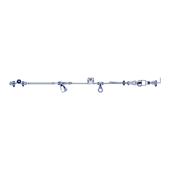
Figure 1 - Typical Sayfline
Anchorage
Anchorage Connector
(Supplied by customer)
Turnbuckle
Labels
1.0
APPLICATION
1.1
PURPOSE: The Sayfline Multi-span Wire Rope Horizontal Lifeline System is designed for use as an anchoring
means for one or two personal fall arrest system (PFAS) or fall restraint system. Use the Sayfline Horizontal
Lifeline (HLL) where horizontal mobility and fall protection is required. The Sayfline Horizontal Lifeline may not be
used for fall protection of material or equipment.
1.2
LIMITATIONS: The following limits apply to the installation and use of Sayfline Multi-span Wire Rope Horizontal
Lifeline System. Other limitations may apply:
IMPORTANT: OSHA regulations state that horizontal lifelines shall be installed and used under the supervision of a
qualified person (see below for definition) as part of a complete personal fall arrest system that maintains a safety
factor of at least two.
Qualified Person: An individual with a recognized degree or professional certificate, and extensive knowledge
and experience in the subject field, who is capable of design, analysis, evaluation, and specification in the
subject work, project, or product. Refer to OSHA 1910.66, 1926.32, and 1926.502.
User Instruction ManualSayfline
Horizontal Lifeline
of an employee training program as required by OSHA.
™
Multi-span Wire Rope Horizontal Lifeline System
Cable
Sayflink Sleeve
Instructions for the following series products:
Sayfline™ Multi-span Wire Rope Horizontal Lifeline
(See back page for specific model numbers.)
™
Multi-span Wire Rope
Zorbit HLL Energy
Absorber
Intermediate
Bracket
Thimble/Cable Clip
End Termination
1
© Copyright 2005, DB Industries, Inc.
Advertisement
Table of Contents

Related Manuals for DBI SALA Sayfline Multi-span Wire Rope Horizontal Lifeline

Summary of Contents for DBI SALA Sayfline Multi-span Wire Rope Horizontal Lifeline
- Page 1 End Termination APPLICATION PURPOSE: The Sayfline Multi-span Wire Rope Horizontal Lifeline System is designed for use as an anchoring means for one or two personal fall arrest system (PFAS) or fall restraint system. Use the Sayfline Horizontal Lifeline (HLL) where horizontal mobility and fall protection is required. The Sayfline Horizontal Lifeline may not be used for fall protection of material or equipment.
-
Page 2: System Requirements
A. HORIZONTAL LIFELINE SPAN: The maximum horizontal lifeline total length is 180 ft. with a Zorbit HLL energy absorber installed on each end of the system. See Figure 1. Systems that are more than 30 ft. in length must include an intermediate bracket for every 30 ft. span. The span length must be reduced when clearance is limited. - Page 3 mechanisms to inadvertently open regardless of how they become oriented. Contact DBI/SALA if you have any questions about compatibility. Connectors (hooks, carabiners, and D-rings) must be capable of supporting at least 5,000 lbs. (22kN). Connectors must be compatible with the anchorage or other system components. Do not use equipment that is not compatible. Non-compatible connectors may unintentionally disengage.
-
Page 4: Installation
E. Directly to webbing or rope lanyard or tie-back (unless the manufacturer’s instructions for both the lanyard and connector specifically allow such a connection). To any object which is shaped or dimensioned such that the snap hook or carabiner will not close and lock, or that roll-out could occur. -
Page 5: System Installation
WARNING: Do not alter or intentionally misuse this equipment. Use caution when using this equipment around moving machinery, electrical and chemical hazards, and sharp edges. SYSTEM INSTALLATION: Figure 1 shows a typical horizontal lifeline system installation. When using an energy absorbing lanyard to connect to the system, the anchorages must be located at a height above the working level which will limit the free fall to six feet. - Page 6 determine the span length and evaluate the required clearance. Figures 6 and 7 apply to one or two users connected to the system. Figure 7 - Self Retracting Lifeline Clearance Requirements Step 2. Determine the correct orientation of the intermediate brackets. Depending on the positioning of the cable, the intermediate brackets may be installed in one of three orientations.
- Page 7 sleeve(s) onto the lifeline before terminating the other Figure 9 - Cable Termination end of the cable to the anchor. Shackles Step 4. If additional intermediate brackets are purchased, Zorbit Shock slide all of the cable guides from the brackets onto Absorber the cable before installing the cable.
-
Page 8: Use Of The System
OPERATION AND USE: WARNING: Consult your doctor if there is reason to doubt your fitness to absorb the impact from a fall arrest. Age and fitness can affect your ability to withstand fall arrest forces. Pregnant women and minors must not use the Sayfline Multi-span Wire Rope Horizontal Lifeline System. - Page 9 rescue. Tolerable suspension time in a full body harness is limited, so a prompt rescue is critical. IMPORTANT: Use care when handling an expended Zorbit energy absorber. The tearing of the energy absorber material produces extremely sharp edges. RESCUE: With the number of potential scenarios for a worker requiring rescue, an on site rescue team is beneficial.
-
Page 10: Specifications
Step 5. Inspect the intermediate brackets for wear or damage. Check brackets to make certain they are securely attached. Make certain all installed Sayflink sleeves pass freely through the intermediate brackets when moving along the system during normal use. Step 6. Inspect system labels. The labels must be present and fully legible. See section 9.0. Replace labels if missing or illegible. - Page 11 LABELING These labels must be present and fully legible: Zorbit Label: Sayfline Labels:...
- Page 12 10.0 COMPONENT DRAWINGS: Zorbit - Part No. 7401013...
- Page 13 Sayflink Sleeve Assembly - Part No. 768002...
- Page 14 Intermediate Bracket - Part No. 7608001 Turnbuckle - Part No. 7002050...
-
Page 15: Inspection And Maintenance Log
11.0 INSPECTION AND MAINTENANCE LOG DATE OF MANUFACTURE: _______________________________________________________________________ MODEL NUMBER: ______________________________________________________________________________ DATE PURCHASED: ________________________________________________________________________________... - Page 16 This instruction applies to the following models: 7603000 7603020 7603040 7603060 7603080 7603100 7603120 7603140 7603160 7603180 7603200 7603220 7608001 Additional model numbers may appear on the next printing of these instructions Canada 3965 Pepin Avenue 260 Export Boulevard Red Wing, MN 55066-1837 Mississauga, Ontario L5S 1Y9 Toll Free: 800-328-6146 Toll Free: 800-387-7484...
Need help?
Do you have a question about the Sayfline Multi-span Wire Rope Horizontal Lifeline and is the answer not in the manual?
Questions and answers