Table of Contents
Advertisement
Quick Links
Advertisement
Table of Contents

Related Manuals for ASROCK J4005DC-ITX


Summary of Contents for ASROCK J4005DC-ITX
- Page 2 (including damages for loss of profits, loss of business, loss of data, interruption of business and the like), even if ASRock has been advised of the possibility of such damages arising from any defect or error in the documentation or product.
- Page 3 If you require assistance please call ASRock Tel : +886-2-28965588 ext.123 (Standard International call charges apply) The terms HDMI®...
-
Page 4: Table Of Contents
Contents Chapter 1 Introduction Package Contents Specifications Motherboard Layout I/O Panel Chapter 2 Installation Installation of Memory Modules (SO-DIMM) Expansion Slot (PCI Express Slot) Jumpers Setup Onboard Headers and Connectors M.2 WiFi/BT Module and Intel® CNVi (Integrated WiFi/BT) Installation Guide Chapter 3 Software and Utilities Operation Installing Drivers Chapter 4 UEFI SETUP UTILITY... - Page 5 4.3.3 Storage Configuration 4.3.4 Super IO Configuration 4.3.5 ACPI Configuration 4.3.6 Trusted Computing Tools Hardware Health Event Monitoring Screen Security Screen Boot Screen Exit Screen...
-
Page 6: Chapter 1 Introduction
ASRock’s website without further notice. If you require technical support related to this motherboard, please visit our website for specific information about the model you are using. You may find the latest VGA cards and CPU support list on ASRock’s website as well. ASRock website http://www.asrock.com. -
Page 7: Specifications
1.2 Specifications Platform • Mini-ITX Form Factor • Solid Capacitor design • Intel® Dual-Core Processor J4025 (up to 2.9 GHz) / J4005 (up to 2.7 GHz) Memory • Dual Channel DDR4 Memory Technology • 2 x DDR4 SO-DIMM Slots * 2GB DRAM per module is not supported. • Supports DDR4 2400/2133 non-ECC, un-buffered memory • Max. - Page 8 J4005DC-ITX Audio • 7.1 CH HD Audio (Realtek ALC887/897 Audio Codec) • Supports Surge Protection • PCIE x1 Gigabit LAN 10/100/1000 Mb/s • Realtek RTL8111H • Supports Wake-On-LAN • Supports Lightning/ESD Protection • Supports Energy Efficient Ethernet 802.3az • Supports PXE Rear Panel • 1 x DC Jack (Compatible with the 19V power adapter)
- Page 9 • Voltage monitoring: +12V, +5V, +3.3V, CPU Vcore • Microsoft® Windows® 10 64-bit * Supports UEFI mode only Certifica- • FCC, CE • ErP/EuP ready (ErP/EuP ready power supply is required) tions * For detailed product information, please visit our website: http://www.asrock.com...
-
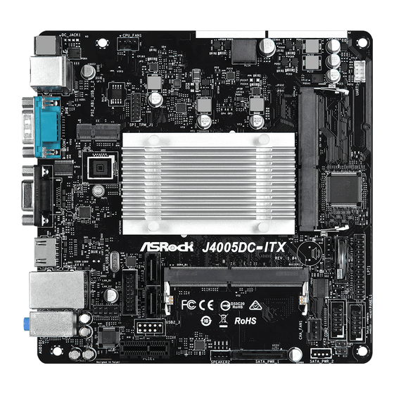
Page 10: Motherboard Layout
J4005DC-ITX 1.3 Motherboard Layout DC Jack CPU_FAN1 BIOS SPI_TPM_J1 LPT1 SPEAKER1 J4005DC-ITX CLRMOS1 USB3_1_2 DDR4_B1 USB 3.1 Gen1 T: USB3 B: USB4 PANEL1 COM2 HD_AUDIO1 CHA_FAN1 RoHS AUDIO CODEC SPEAKER2 PCIE1 SATA_PWR_1... - Page 11 No. Description CPU Fan Connector (CPU_FAN1) 2 x 260-pin DDR4 SO-DIMM Slots (DDR4_A1, DDR4_B1) Chassis Speaker Header (SPEAKER1) Print Port Header (LPT1) Clear CMOS Jumper (CLRMOS1) System Panel Header (PANEL1) COM Port Header (COM2) Chassis Intrusion Header (CI1) Chassis Fan Connector (CHA_FAN1) SATA Power Connector (SATA_PWR_1) 3W Audio AMP Output Wafer Header (SPEAKER2) SATA3 Connector (SATA3_1)
-
Page 12: I/O Panel
J4005DC-ITX 1.4 I/O Panel No. Description No. Description USB 2.0 Ports (USB_1_2) HDMI Port LAN RJ-45 Port* D-Sub Port Line In (Light Blue) COM Port Front Speaker (Lime) PS/2 Mouse/Keyboard Port Microphone (Pink) DC Jack USB 3.1 Gen1 Ports (USB3_3_4) * There are two LEDs on each LAN port. -
Page 13: Chapter 2 Installation
Chapter 2 Installation This is a Mini-ITX form factor motherboard. Before you install the motherboard, study the configuration of your chassis to ensure that the motherboard fits into it. Pre-installation Precautions Take note of the following precautions before you install motherboard components or change any motherboard settings. -
Page 14: Installation Of Memory Modules (So-Dimm)
J4005DC-ITX 2.1 Installation of Memory Modules (SO-DIMM) This motherboard provides two 260-pin DDR4 (Double Data Rate 4) SO-DIMM slots, and supports Dual Channel Memory Technology. 1. It is not allowed to install a DDR, DDR2 or DDR3 memory module into a DDR4 slot;... -
Page 16: Expansion Slot (Pci Express Slot)
J4005DC-ITX 2.2 Expansion Slot (PCI Express Slot) There is 1 PCI Express slot on the motherboard. Before installing an expansion card, please make sure that the power supply is switched off or the power cord is unplugged. Please read the documentation of the expansion card and make necessary hardware settings for the card before you start the installation. -
Page 17: Jumpers Setup
2.3 Jumpers Setup The illustration shows how jumpers are setup. When the jumper cap is placed on the pins, the jumper is “Short”. If no jumper cap is placed on the pins, the jumper is “Open”. *The jumper cap is not provided. Clear CMOS Jumper Short: Clear CMOS (CLRCMOS1) -
Page 18: Onboard Headers And Connectors
J4005DC-ITX 2.4 Onboard Headers and Connectors Onboard headers and connectors are NOT jumpers. Do NOT place jumper caps over these headers and connectors. Placing jumper caps over the headers and connectors will cause permanent damage to the motherboard. System Panel Header... - Page 19 Serial ATA3 Connectors These two SATA3 (SATA3_1: connectors support SATA see p.5, No. 12) data cables for internal (SATA3_2: storage devices with up to see p.5, No. 15) 6.0 Gb/s data transfer rate. SATA Power Connector Please connect a SATA (SATA_PWR_1) power cable.
- Page 20 J4005DC-ITX Chassis Speaker Header Please connect the chassis SPEAKER (4-pin SPEAKER1) speaker to this header. DUMMY DUMMY (see p.5, No. 3) Front_L- 3W Audio AMP Output Please connect the chassis Front_L+ Wafer Header Front_R+ speaker to this header. Front_R- (4-pin SPEAKER2) (see p.5, No.
- Page 21 Chassis Intrusion Header This motherboard (2-pin CI1) supports CASE OPEN Signal (see p.5, No. 8) detection feature that detects if the chassis cove has been removed. This feature requires a chassis with chassis intrusion detection design. SPI TPM Header This connector supports SPI TPM_PIRQ RST# SPI_TPM_CS#...
-
Page 22: Wifi/Bt Module And Intel® Cnvi (Integrated Wifi/Bt) Installation Guide
J4005DC-ITX 2.5 M.2 WiFi/BT Module and Intel® CNVi (Integrated WiFi/BT) Installation Guide The M.2, also known as the Next Generation Form Factor (NGFF), is a small size and versatile card edge connector that aims to replace mPCIe and mSATA. The M.2 Socket (Key E) supports type 2230 WiFi/BT module and Intel®... - Page 23 Step 4 Tighten the screw with a screwdriver to secure the module into place. Please do not overtighten the screw as this might damage the module.
-
Page 24: Chapter 3 Software And Utilities Operation
J4005DC-ITX Chapter 3 Software and Utilities Operation 3.1 Installing Drivers The Support CD that comes with the motherboard contains necessary drivers and useful utilities that enhance the motherboard’s features. Running The Support CD To begin using the support CD, insert the CD into your CD-ROM drive. The CD automatically displays the Main Menu if “AUTORUN”... -
Page 25: Chapter 4 Uefi Setup Utility
Chapter 4 UEFI SETUP UTILITY 4.1 Introduction This section explains how to use the UEFI SETUP UTILITY to configure your system. You may run the UEFI SETUP UTILITY by pressing <F2> or <Del> right after you power on the computer, otherwise, the Power-On-Self-Test (POST) will continue with its test routines. -
Page 26: Navigation Keys
J4005DC-ITX 4.1.2 Navigation Keys Use < > key or < > key to choose among the selections on the menu bar, and use < > key or < > key to move the cursor up or down to select items, then press <Enter>... -
Page 27: Main Screen
4.2 Main Screen When you enter the UEFI SETUP UTILITY, the Main screen will appear and display the system overview. -
Page 28: Advanced Screen
J4005DC-ITX 4.3 Advanced Screen In this section, you may set the configurations for the following items: CPU Configuration, Chipset Configuration, Storage Configuration, Super IO Con- figuration, ACPI Configuration and Trusted Computing.. Setting wrong values in this section may cause the system to malfunction. -
Page 29: Cpu Configuration
4.3.1 CPU Configuration Intel SpeedStep Technology Intel SpeedStep technology allows processors to switch between multiple frequencies and voltage points for better power saving and heat dissipation. CPU C States Support Enable CPU C States Support for power saving. It is recommended to keep C1 and C6 all enabled for better power saving. -
Page 30: Chipset Configuration
J4005DC-ITX 4.3.2 Chipset Configuration Primary Graphics Adapter Select a primary VGA. Share Memory Configure the size of memory that is allocated to the integrated graphics processor when the system boots up. Onboard HD Audio Enable/disable onboard HD audio. Set to Auto to enable onboard HD audio and automatically disable it when a sound card is installed. - Page 31 WAN Radio Enable/disable the WiFi module's connectivity. BT Enabled Enable/disable the Bluetooth module's connectivity. Deep S5 Configure deep sleep mode for power saving when the computer is shut down. Restore on AC/Power Loss Select the power state after a power failure. If [Power Off] is selected, the power will remain off when the power recovers.
-
Page 32: Storage Configuration
J4005DC-ITX 4.3.3 Storage Configuration SATA Controller(s) Enable/disable the SATA controllers. SATA Mode Selection AHCI: Supports new features that improve performance. AHCI (Advanced Host Controller Interface) supports NCQ and other new features that will improve SATA disk performance. SATA Aggressive Link Power Management SATA Aggressive Link Power Management allows SATA devices to enter a low power state during periods of inactivity to save power. -
Page 33: Super Io Configuration
4.3.4 Super IO Configuration Serial Port 1 Enable or disable the Serial port 1. Serial Port Address Select the address of the Serial port. Serial Port 2 Enable or disable the Serial port 2. Serial Port Address Select the address of the Serial port. Parallel Port Enable or disable the Parallel port. - Page 34 J4005DC-ITX PS2 Y-Cable Enable the PS2 Y-Cable or set this option to Auto.
-
Page 35: Acpi Configuration
4.3.5 ACPI Configuration Suspend to RAM It is recommended to select auto for ACPI S3 power saving. ACPI HPET Table Enable the High Precision Event Timer for better performance and to pass WHQL tests. PS/2 Keyboard Power On Allow the system to be waked up by a PS/2 Keyboard. PCIE Device Power On Allow the system to be waked up by a PCIE device and enable wake on LAN. - Page 36 J4005DC-ITX USB Keyboard/Remote Power On Allow the system to be waked up by an USB keyboard or remote controller. USB Mouse Power On Allow the system to be waked up by an USB mouse.
-
Page 37: Trusted Computing
4.3.6 Trusted Computing NOTE: Options vary depending on the version of your connected TPM module. Security Device Support Use this item to enable or disable BIOS support for security device. O.S. will not show Security Device. TCG EFI protocol and INT1A interface will not be available. SHA-1 PCR Bank Use this item to enable or disable SHA-1 PCR Bank. - Page 38 J4005DC-ITX TPM2.0 UEFI Spec Version Use this item to select the TCG2 spec. version supported. The optional settings: [TCG_1_2]; [TCG_2]. [TCG_1_2]: compatible mode for Win8/Win10. [TCG_2]: for TCG2 newer spec. compatible mode for Win10 Physical Presence Spec version Select this item to tell OS to support PPI spec version 1.2 or 1.3. Please note that some HCK tests might not support version 1.3.
-
Page 39: Tools
Save UEFI files in your USB storage device and run Instant Flash to update your UEFI. Internet Flash ASRock Internet Flash downloads and updates the latest UEFI firmware version from our servers for you. Please setup network configuration before using Internet Flash. - Page 40 J4005DC-ITX Network Configuration Use this to configure internet connection settings for Internet Flash. Internet Setting Enable or disable sound effects in the setup utility. UEFI Download Server Select a server to download the UEFI firmware.
-
Page 41: Hardware Health Event Monitoring Screen
4.5 Hardware Health Event Monitoring Screen This section allows you to monitor the status of the hardware on your system, including the parameters of the CPU temperature, motherboard temperature, fan speed and voltage. CPU Fan 1 Setting This allows you to set CPU fan 1’s speed. Configuration options: [Full On] and [Automatic Mode]. -
Page 42: Security Screen
J4005DC-ITX 4.6 Security Screen In this section you may set or change the supervisor/user password for the system. You may also clear the user password. Supervisor Password Set or change the password for the administrator account. Only the administrator has authority to change the settings in the UEFI Setup Utility. Leave it blank and press enter to remove the password. -
Page 43: Boot Screen
4.7 Boot Screen This section displays the available devices on your system for you to configure the boot settings and the boot priority. Fast Boot Fast Boot minimizes your computer's boot time. In fast mode you may not boot from an USB storage device. The VBIOS must support UEFI GOP if you are using an external graphics card. - Page 44 J4005DC-ITX Full Screen Logo Enable to display the boot logo or disable to show normal POST messages. CSM (Compatibility Support Module) Enable to launch the Compatibility Support Module. Please do not disable unless you’re running a WHCK test.
-
Page 45: Exit Screen
4.8 Exit Screen Save Changes and Exit When you select this option the following message, “Save configuration changes and exit setup?” will pop out. Select [OK] to save changes and exit the UEFI SETUP UTILITY. Discard Changes and Exit When you select this option the following message, “Discard changes and exit setup?”... - Page 46 Contact Information If you need to contact ASRock or want to know more about ASRock, you’re welcome to visit ASRock’s website at http://www.asrock.com; or you may contact your dealer for further information. For technical questions, please submit a support request form at https://event.asrock.com/tsd.asp...
- Page 47 DECLARATION OF CONFORMITY Per FCC Part 2 Section 2.1077(a) Responsible Party Name: ASRock Incorporation Address: 13848 Magnolia Ave, Chino, CA91710 Phone/Fax No: +1-909-590-8308/+1-909-590-1026 hereby declares that the product Product Name : Motherboard J4005DC-ITX Model Number : Conforms to the following speci cations:...
- Page 48 EU Declaration of Conformity For the following equipment: Motherboard (Product Name) J4005DC-ITX/ ASRock (Model Designation / Trade Name) ASRock Incorporation (Manufacturer Name) 2F., No.37, Sec. 2, Jhongyang S. Rd., Beitou District, Taipei City 112, Taiwan (R.O.C.) (Manufacturer Address) EMC —Directive 2014/30/EU (from April 20th, 2016)
Need help?
Do you have a question about the J4005DC-ITX and is the answer not in the manual?
Questions and answers