Festo MPS 200 Getting Started
Hide thumbs
Also See for MPS 200:
- Getting started (64 pages) ,
- Operating instructions manual (132 pages)

Related Manuals for Festo MPS 200


Summary of Contents for Festo MPS 200
- Page 1 8064835 ® System 203 Industry 4.0 ® Complete Systems Kurzanleitung Getting started Festo Didactic 8064836 de/en 03/2017 R1.0...
- Page 2 03/2017 Authors: Frank Ebel, Mustafa Ersoy, Christian Hartung Layout: 04/2017, Susanne Durz, Frank Ebel © Festo Didactic SE, Rechbergstraße 3, 73770 Denkendorf, Germany, 2017 +49 711 3467-0 www.festo-didactic.com +49 711 34754-88500 did@festo.com Weitergabe sowie Vervielfältigung dieses Dokuments, Verwertung und Mitteilung seines Inhalts verboten, soweit nicht ausdrücklich gestattet.
-
Page 3: Table Of Contents
Die Station Fügen Industrie 4.0 ________________________________________________________ 21 Die Station Sortieren Industrie 4.0 _____________________________________________________ 23 Funktion ___________________________________________________________________________ 24 Ablaufbeschreibung _________________________________________________________________ 24 10.1 Startvoraussetzung __________________________________________________________________ 24 10.2 Ausgangsstellung ___________________________________________________________________ 24 10.3 Richten ____________________________________________________________________________ 25 10.4 Stationen Starten ___________________________________________________________________ 25 10.5 Ablauf _____________________________________________________________________________ 25 © Festo Didactic 8064836... - Page 4 Montage von Profilplatte und Bedienpult ________________________________________________ 31 11.7 Kabelverbindungen __________________________________________________________________ 31 11.8 Spannungsversorgung _______________________________________________________________ 32 11.9 SPS Programme laden _______________________________________________________________ 32 11.10 Ablauf starten ______________________________________________________________________ 32 Wartung und Pflege _________________________________________________________________ 33 Weitere Informationen und Aktualisierungen ___________________________________________ 33 © Festo Didactic 8064836...
-
Page 5: Allgemeine Voraussetzungen Zum Betreiben Der Geräte
Es dürfen keine Geräte mit Schäden oder Mängeln verwendet werden. – Schadhafte Geräte sind zu sperren und aus dem Labor- oder Unterrichtsraum zu entnehmen. – Beschädigte Verbindungsleitungen, Druckluftschläuche und Hydraulikschläuche stellen ein Sicherheitsrisiko dar und müssen aus dem Labor- oder Unterrichtsraum entfernt werden. © Festo Didactic 8064836... -
Page 6: Piktogramme
Regeln gebaut. Dennoch können bei unsachgemäßer Verwendung Gefahren für Leib und Leben des Benutzers oder Dritter und Beeinträchtigungen der Komponenten entstehen. Das Lernsystem von Festo Didactic ist ausschließlich für die Aus- und Weiterbildung im Bereich Automatisierung und Technik entwickelt und hergestellt. Das Ausbildungsunternehmen und/oder die Ausbildenden hat/haben dafür Sorge zu tragen, dass die Auszubildenden die Sicherheitsvorkehrungen, die... -
Page 7: Für Ihre Sicherheit
Stand der Technik und den anerkannten sicherheitstechnischen Regeln gebaut. Dennoch können bei ihrer Verwendung Gefahren für Leib und Leben des Benutzers oder Dritter bzw. Beeinträchtigungen an der Maschine oder an anderen Sachwerten entstehen. © Festo Didactic 8064836... -
Page 8: Arbeits- Und Sicherheitshinweise
Benutzen Sie zur Betätigung der Grenztaster ein Werkzeug, z. B. einen Schraubendreher. • Stellen Sie alle Komponenten so auf, dass das Betätigen von Schaltern und Trenneinrichtungen nicht erschwert wird. • Beachten Sie Angaben zur Platzierung der Komponenten. © Festo Didactic 8064836... - Page 9 Einige Geräte haben einen hohen Ableitstrom. Diese Geräte müssen zusätzlich mit einem Schutzleiter geerdet werden. • Wenn in den Technischen Daten nicht anders angegeben, besitzt das Gerät keine integrierte Sicherung. • Ziehen Sie beim Abbauen der Verbindungsleitungen nur an den Sicherheitssteckern, nicht an den Leitungen. © Festo Didactic 8064836...
- Page 10 Lärm durch ausströmende Druckluft kann schädlich für das Gehör sein. Reduzieren Sie den Lärm durch den Einsatz von Schalldämpfern oder tragen Sie einen Gehörschutz, falls der Lärm sich nicht vermeiden lässt. – Alle Abluftanschlüsse der Komponenten der Gerätesätze sind mit Schalldämpfern versehen. Entfernen Sie diese Schalldämpfer nicht. © Festo Didactic 8064836...
-
Page 11: Technische Daten
4 A gesamt Elektrischer Anschluss 24-polige IEEE-488 Buchse (SysLink) RJ-45 Netzwerkanschluss Pneumatischer Anschluss Kunststoffschlauch mit 6 mm Außendurchmesser Druckluftverbrauch bei 600 kPa (Dauerzyklus) 10 l/min Maße 1050 mm x 700 mm x 1240 mm Änderungen vorbehalten © Festo Didactic 8064836... -
Page 12: Kontaktbelegungstabelle Station Verteilen/Band Mit Signalsäule Am Bedienfeld
24 V Versorgung der Ausgänge 24 V B 21+22 weiß-rosa 24 V Versorgung der Eingänge GND A braun-rosa 0 V Versorgung der Ausgänge GND A lila 0 V Versorgung der Ausgänge GND B 23+24 weiß-blau 0 V Versorgung der Eingänge © Festo Didactic 8064836... - Page 13 Signalsäule Digital (Bedienfeld XG2) Funktion SysLink Farbe Benennung rosa Ampel rot blau Ampel gelb Ampel grün GND A braun-rosa 0 V Versorgung der Ausgänge Hinweis Bei allen Vorzugsvarianten SPS sind Kabelbrücken von NOT-AUS auf Bit 1.5 gesteckt. © Festo Didactic 8064836...
-
Page 14: Kontaktbelegungstabelle Station Fügen
GND A lila 0 V Versorgung der Ausgänge GND B 23+24 weiß-blau 0 V Versorgung der Eingänge Analog Funktion D-SUB-15 Farbe Benennung Abstandssensor analog Hinweis Bei allen Vorzugsvarianten SPS sind Kabelbrücken von NOT-AUS auf Bit 1.5 gesteckt. © Festo Didactic 8064836... - Page 15 Bei XG2 laufen alle Signale über einen Busknoten, bei dem die Signale – je nach Steuerung – mit einem anderen Protokoll angesprochen werden. • Bei einer Siemens SPS: ProfiNet, • bei einer Allen Bradley SPS: Ethernet IP © Festo Didactic 8064836...
-
Page 16: Kontaktbelegungstabelle Station Sortieren
0 V Versorgung der Ausgänge GND A lila 0 V Versorgung der Ausgänge GND B 23+24 weiß-blau 0 V Versorgung der Eingänge Hinweis Bei allen Vorzugsvarianten SPS sind Kabelbrücken von NOT-AUS auf Bit 1.5 gesteckt. © Festo Didactic 8064836... -
Page 17: Vernetzung Des Systems
Dieser Switch ist hinter der Steuerung im Wagen der MPS ® Station Verteilen/Band. Daten-/Versorgungsleitung Siemens SIMATIC S7-1500 PROFINET Leitung 5-Port Switch RFID Schreib-/Lesekopf PC für MES System RFID Gateway mit RFID Modul PROFINET Busknoten © Festo Didactic 8064836... -
Page 18: Transport/Auspacken/Lieferumfang
Stationen werden in einer Transportbox mit Palettenboden geliefert. Die Transportbox darf ausschließlich mit geeigneten Hubwagen oder Gabelstaplern transportiert werden. Die Transportbox muss gegen Umfallen und Herunterfallen gesichert sein. Transportschäden sind unverzüglich dem Spediteur und Festo Didactic zu melden. 7.2 Auspacken ... -
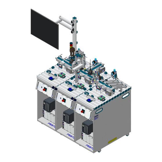
Page 19: Aufbau
Anlage 203 Industrie 4.0 ® 8 Aufbau 8.1 Die MPS ® Anlage 203 Industrie 4.0 Draufsicht; von links nach rechts: Station Verteilen/Band, Station Fügen, Station Sortieren © Festo Didactic 8064836... -
Page 20: Die Station Verteilen/Band Industrie 4.0
Anlage 203 Industrie 4.0 mit einer Signalsäule, die am Bedienfeld ® angeschlossen ist, und dem Modul RFID erweitert. Nachdem ein Werkstückkörper aus dem Modul Stapelmagazin ausgeschoben wurde, schreibt der RFID Schreib-/Lesekopf die Auftragsnummer, die Positionsnummer sowie Funktionen auf den RFID Tag im Werkstückkörper. © Festo Didactic 8064836... -
Page 21: Die Station Fügen Industrie 4.0
Werkstückdeckel auf die MPS Werkstückkörper zu fügen ® Hinweis Mit der Station Fügen ist es möglich, µController-Werkstückdeckel auf die MPS ® Werkstückkörper zu fügen. Hierfür benötigen Sie den Anbausatz 8064882, um vom Sauggreifer auf einen Greifer mit Greifbacken umzurüsten. © Festo Didactic 8064836... - Page 22 Die Werkstücke müssen einzeln transportiert werden, damit die Unterscheidung der Werkstücke sowie der Fügeprozess nicht behindert werden. Ausgangssignale des Abstandssensors Der Abstandssensor liefert sowohl ein analoges als auch ein binäres Ausgangssignal. Der binäre Schaltausgang lässt sich durch einfaches Teach-In auf die Messanforderung einstellen. © Festo Didactic 8064836...
-
Page 23: Die Station Sortieren Industrie 4.0
Schreib-/Lesekopf wird der RFID Tag im Werkstück gelesen und je nach Ergebnis das Werkstück ausgeschleust. Die Aufgabe der Station Sortieren Industrie 4.0 ist es • Werkstücke nach Beschaffenheit zu sortieren • Werkstücke nach Inhalt des RFID Tags zu sortieren © Festo Didactic 8064836... -
Page 24: Funktion
10.1 Startvoraussetzung • Werkstücke im Modul Stapelmagazin vorhanden. • Keine Werkstücke im Materialfluss der Anlage. • Alle Stationen in Ausgangsstellung und gestartet. 10.2 Ausgangsstellung • Bandmotoren der Stationen aus • Stopper ausgefahren • Rutschen nicht voll © Festo Didactic 8064836... -
Page 25: Richten
10. Bandmotor Station Fügen ein 11. Werkstückerkennung bei Bandanfang Station Fügen 12. Bandmotor Station Verteilen/Band aus 13. Werkstückvermessung am Bandanfang der Station Fügen 14. Werkstück hält zum Lesen/Schreiben am ersten RFID Schreib-/Lesekopf bei Station Fügen 15. RFID Tag wird ausgelesen © Festo Didactic 8064836... - Page 26 44. Werkstück hält zum Lesen/Schreiben am zweiten RFID Schreib-/Lesekopf der Station Fügen 45. RFID Tag mit Werkstückstatus wird aktualisiert 46. Bandmotor Station Fügen ein 47. Werkstückerkennung bei Bandende erstes Band 48. Bandmotor Station Sortieren ein 49. Werkstückerkennung bei Bandanfang Station Sortieren 50. Bandmotor Station Fügen aus © Festo Didactic 8064836...
- Page 27 60. Zweite Weiche ausgefahren 61. Werkstück ausgeschleust 62. Zweite Weiche eingefahren 63. Bandmotor aus Farbprüfung war nicht erfolgreich 64. Umlenkung lenkt Werkstück auf letzte Rutsche 65. Werkstück ausgeschleust 66. Bandmotor aus 67. Anlage bereit für nächsten Durchlauf © Festo Didactic 8064836...
-
Page 28: Inbetriebnahme
Werden die Stationen Verteilen/Band und Fügen mit Folgestationen betrieben, müssen die Stopper am Ende des Moduls Band demontiert werden. Aufbau als Einzelstation, der Stopper am Bandende ist montiert Aufbau mit Folgestation, der Stopper am Bandende ist demontiert © Festo Didactic 8064836... -
Page 29: Pneumatische Inbetriebnahme
Stationen, sind hierzu mitgeliefert. Sollte eine Verlängerung der Leitung der Verteilerleiste notwendig sein, ist dies nur von einem ausgebildeten Fachmann auszuführen. Die Steckdose hierfür muss, den Verbrauchern entsprechend, abgesichert sein. Um Probleme im Betrieb zu vermeiden, ist eine Einzelabsicherung (16 A) der Anlage dringend empfohlen. © Festo Didactic 8064836... -
Page 30: 1-Bit Kommunikationsverbindungen Herstellen
SPS Board mit 16 digitalen Ein- und Ausgängen • ein Netzgerät 24 V DC, 4,5 A • eine Druckluftversorgung mit 600 kPa (6 bar) • einen PC mit installierter SPS Programmiersoftware • zwei E/A-Kabel (SysLink) © Festo Didactic 8064836... -
Page 31: Montage Von Profilplatte Und Bedienpult
Stecken Sie die 4 mm Sicherheitsstecker in die Buchsen des Netzgerätes. PC – SPS Verbinden Sie Ihren PC durch ein Programmierkabel mit der SPS. SPS – Busknoten Verbinden Sie die SPS durch eine Busleitung mit dem Busknoten © Festo Didactic 8064836... -
Page 32: Spannungsversorgung
Gehen Sie zum Laden der SPS Programme so vor, wie es in den Benutzerhandbüchern der von Ihnen verwendeten Programmiersoftware beschrieben ist. Aktuelle SPS Programme für verschiedene Steuerungen finden Sie im Internet unter folgender Adresse: www.festo-didactic.com > Service > MPS® Mechatronische Systeme > Stationen 11.10 Ablauf starten 1. -
Page 33: Wartung Und Pflege
Es dürfen keine aggressiven oder scheuernden Reinigungsmittel verwendet werden. 13 Weitere Informationen und Aktualisierungen Weiter Informationen und Aktualisierungen zur Technischen Dokumentation der MPS Stationen finden Sie im Internet unter der Adresse: www.festo-didactic.com > Service > Mechatronische Systeme ® © Festo Didactic 8064836... - Page 34 Anlage 203 Industrie 4.0 ® © Festo Didactic 8064836...
- Page 35 The Sorting station Industry 4.0 _______________________________________________________ 55 Function ___________________________________________________________________________ 56 Sequence description _______________________________________________________________ 56 10.1 Start-up prerequisites _______________________________________________________________ 56 10.2 Initial position ______________________________________________________________________ 56 10.3 Resetting __________________________________________________________________________ 57 10.4 Starting the stations _________________________________________________________________ 57 10.5 Sequence __________________________________________________________________________ 57 © Festo Didactic 8064836...
- Page 36 Mounting the profile plate and the control console ________________________________________ 63 11.7 Cable connections ___________________________________________________________________ 63 11.8 Power supply _______________________________________________________________________ 64 11.9 Loading PLC programs _______________________________________________________________ 64 11.10 Starting the sequence _______________________________________________________________ 64 Maintenance and care _______________________________________________________________ 65 Further information and updates ______________________________________________________ 65 © Festo Didactic 8064836...
-
Page 37: General Prerequisites For Operating The Devices
Damaged devices must be banned from further use and removed from the laboratory or classroom. – Damaged connecting cables, pneumatic tubing and hydraulic hoses represent a safety risk and must be removed from the laboratory or classroom. © Festo Didactic 8064836... -
Page 38: Pictograms
Festo Didactic hereby excludes any and all liability for damages suffered by trainees, the training company and/or any third parties, which occur during use of the equipment sets in situations which serve any purpose other than training and/or vocational education, unless such damages have been caused by Festo Didactic due to malicious intent or gross negligence. -
Page 39: For Your Safety
However, life and limb of the user and third parties may be endangered and the machine or other property may be damaged during its use. © Festo Didactic 8064836... -
Page 40: Work And Safety Instructions
Risk of injury during troubleshooting! Use a tool such as a screwdriver to actuate limit switches. • Set all components up so that it is easy to activate the switches and interrupters. • Follow the instructions about positioning the components. © Festo Didactic 8064836... - Page 41 • The device is not equipped with an integrated fuse unless specified otherwise in the technical data. • Always pull on the plug when disconnecting connecting cables – never pull the cable. © Festo Didactic 8064836...
- Page 42 Noise caused by escaping compressed air may damage your hearing. Reduce noise by using silencers, or wear hearing protection if noise cannot be avoided. – All of the exhaust ports for the components included in the equipment set are equipped with silencers. Do not remove these silencers. © Festo Didactic 8064836...
-
Page 43: Technical Data
24-pin IEEE-488 socket (SysLink) RJ-45 network connection Pneumatic connection Plastic tubing with 6 mm outside diameter Compressed air consumption at 600 kPa (continuous cycle) 10 l/min. Dimensions 1050 mm x 700 mm x 1240 mm Subject to change © Festo Didactic 8064836... -
Page 44: Terminal Assignment Table Distributing/Conveyor Station With Signal Column At The Control Panel
21+22 White-pink 24 V power supply for inputs GND A Brown-pink 0 V power supply for outputs GND A Purple 0 V power supply for outputs GND B 23+24 White-blue 0 V power supply for inputs © Festo Didactic 8064836... - Page 45 Designation Pink Light is red Blue Light is yellow Light is green GND A Brown-pink 0 V power supply for outputs Note Cable jumpers are connected from emergency off to bit 1.5 on all PLC variants. © Festo Didactic 8064836...
-
Page 46: Terminal Assignment Table Joining Station
0 V power supply for outputs GND B 23+24 White-blue 0 V power supply for inputs Analog Function D-SUB-15 Color Designation Distance sensor, analog Note Cable jumpers are connected from emergency off to bit 1.5 on all PLC variants. © Festo Didactic 8064836... - Page 47 In the case of XG2, all signals are transmitted via a bus node which addresses the signals with different protocols depending on the controller. • For Siemens PLCs: ProfiNet, • For Allen Bradley PLCs: Ethernet IP © Festo Didactic 8064836...
-
Page 48: Terminal Assignment Table Sorting Station
0 V Versorgung der Ausgänge GND A Purple 0 V Versorgung der Ausgänge GND B 23+24 White-blue 0 V Versorgung der Eingänge Note Cable jumpers are connected from emergency off to bit 1.5 on all PLC variants. © Festo Didactic 8064836... -
Page 49: Networking The System
® Distributing/Conveyor station. Data/supply cable Siemens SIMATIC S7-1500 PROFINET cable 5-Port Switch RFID write/read head PC for MES RFID gateway with RFID module PROFINET bus node © Festo Didactic 8064836... -
Page 50: Transport, Unpacking, Delivery
Examine the station for possible damage after unpacking. The freight forwarder and Festo Didactic must be notified of any damage without delay. 7.3 Delivery Check delivered items against the delivery note and the purchase order. Festo Didactic must be notified of any discrepancies without delay. © Festo Didactic 8064836... -
Page 51: Design
System 203 Industry 4.0 ® 8 Design 8.1 The MPS ® System 203 Industry 4.0 Top view, from left to right: distributing/conveyor station, joining station, sorting station © Festo Didactic 8064836... -
Page 52: The Distributing/Conveyor Station Industry 4.0
After the workpiece base has been pushed out of the stacking magazine module, the RFID read/write head writes the work order number, the item number and the functions to the RFID tag in the workpiece base. © Festo Didactic 8064836... -
Page 53: The Joining Station Industry 4.0
Microcontroller workpiece caps can be mounted on the MPS ® workpiece bases with the station. This requires a mounting kit (8064882) in order to switch over from a suction gripper to a mechanical gripper with gripper jaws. © Festo Didactic 8064836... - Page 54 Distance sensor output signals The distance sensor transmits both an analog and a binary output signal. The binary switching output can be adapted to the measurement requirement via a simple teach-in process. © Festo Didactic 8064836...
-
Page 55: The Sorting Station Industry 4.0
RFID read/write head and, depending on the results, the workpiece is ejected. The function of the Sorting station Industry 4.0 is to: • Sort workpieces according to their characteristics • Sort workpieces according to RFID tag content © Festo Didactic 8064836... -
Page 56: Function
Workpieces available in the Stacking Magazine module. • No workpieces in the system's material flow process. • All stations in initial position and started up. 10.2 Initial position • Belt motors off at the stations • Stopper advanced • Chutes not full © Festo Didactic 8064836... -
Page 57: Resetting
13. The workpiece is measured at the start of the Joining station’s conveyor belt. 14. The workpiece is stopped at the Joining station’s first RFID write/read head for reading/writing. 15. The RFID tag is read out. © Festo Didactic 8064836... - Page 58 46. Joining station motor on. 47. The workpiece is detected at the end of the first conveyor. 48. Sorting station motor on 49. Workpiece is detected at the start of the Sorting station’s conveyor. 50. Joining station motor off. © Festo Didactic 8064836...
- Page 59 62. The second deflector is retracted. 63. Conveyor motor off Color checking unsuccessful 64. The baffle sends the workpiece to the last chute. 65. The workpiece is discharged. 66. Conveyor motor off 67. System ready for next run © Festo Didactic 8064836...
-
Page 60: Commissioning
Setup as individual station – the stopper at the end of the Setup with downstream station – the stopper at the end of the conveyor is mounted conveyor is removed © Festo Didactic 8064836... -
Page 61: Pneumatic Commissioning
If the cable length from the distributor block needs to be increased, this can only be carried out by appropriately trained, skilled personnel. The plug socket used must be fused appropriately for the consuming devices. In order to avoid problems during operation, individual fusing (16 A) of the system is strongly recommended. © Festo Didactic 8064836... -
Page 62: Establishing 1-Bit Communication Links
A PLC board with 16 digital inputs and outputs • A power pack: 24 V DC, 4.5 A • Compressed air supply: 600 kPa (6 bar) • A PC with installed PLC programming software and FCT software • Two I/O cables (SysLink) © Festo Didactic 8064836... -
Page 63: Mounting The Profile Plate And The Control Console
Insert the 4 mm safety plugs into the sockets on the power pack. PC to PLC Connect your PC to the PLC via a programming cable. PLC to bus node Connect the PLC to the bus node using a bus line. © Festo Didactic 8064836... -
Page 64: Power Supply
Current PLC programs for various controllers can be found on the Internet at the following website: www.festo-didactic.com > Services > MPS® The Modular Production System > Stations 11.10 Starting the sequence 1. Check power supply and compressed air supply. -
Page 65: Maintenance And Care
Do not use aggressive or abrasive cleaning agents. 13 Further information and updates Further information and updates for technical documentation for MPS stations are available on the following website: www.festo-didactic.com > Services > MPS® The Modular Production System © Festo Didactic 8064836... - Page 66 System 203 Industry 4.0 ® © Festo Didactic 8064836...
- Page 68 Festo Didactic SE Rechbergstraße 3 73770 Denkendorf Germany +49 711 3467-0 www.festo-didactic.com +49 711 34754-88500 did@festo.com...
Need help?
Do you have a question about the MPS 200 and is the answer not in the manual?
Questions and answers