Table of Contents
Advertisement
Quick Links
[
[
PU REC
TECHNICAL REFERENCE MANUAL
WELCOME TO
THE WORLD OF
DEWETRON!
Congratulations on your new device! It
will supply you with accurate, complete
and reproducible measurement results
for your decision making.
ISO9001
Look forward to the easy handling and
the flexible and modular use of your
DEWETRON product and draw upon
more than 30 years of DEWETRON
EN ISO 14001
expertise in measurement engineering.
THE MEASURABLE DIFFERENCE.
Advertisement
Table of Contents

Subscribe to Our Youtube Channel
Related Manuals for Dewetron PUREC


Summary of Contents for Dewetron PUREC
- Page 1 ISO9001 Look forward to the easy handling and the flexible and modular use of your DEWETRON product and draw upon more than 30 years of DEWETRON EN ISO 14001 expertise in measurement engineering. THE MEASURABLE DIFFERENCE.
- Page 2 Copyright © DEWETRON GmbH This document contains information which is protected by copyright. All rights are reserved. Reproduction, adaptation, or translation without prior written permission is prohibited, except as allowed under the copyright laws. All trademarks and registered trademarks are acknowledged to be the property of their owners.
- Page 3 This guide includes important startup notes, as well as safety notes and information about keeping your DEWETRON system in good working condition over time.
- Page 4 PREFACE Notes...
-
Page 5: Table Of Contents
Service/Repair Policy…………………………………………………………………………………………………………… 7 Warranty Information ………………………………………………………………………………………………………… 8 Printing History …………………………………………………………………………………………………………………… 8 Safety conventions ……………………………………………………………………………………………………………… 9 General safety and hazard warnings for all DEWETRON systems ………………………………………… 10 Maintenance ……………………………………………………………………………………………………………………… 13 Service interval: ………………………………………………………………………………………………………………………………………… 13 Cleaning: …………………………………………………………………………………………………………………………………………………… 13 Windows updates and antivirus/security software ……………………………………………………………… 14 Problematic network stacks …………………………………………………………………………………………………... - Page 6 TABLE OF CONTENT Synchronization options ……………………………………………………………………………………………………… 48 Synchronization via SYNC-BUS ………………………………………………………………………………………………………………… 48 Data transfer (independent from synchronization) …………………………………………………………………………………… 48 Cooling considerations………………………………………………………………………………………………………… 49 Dimensions ………………………………………………………………………………………………………………………… 50 Maintenance ……………………………………………………………………………………………………………………… 51 Maintenance intervals ……………………………………………………………………………………………………………………………… 51 Removing the intake vent and cleaning the filter pad ……………………………………………………………………………… 51 Letter of volatility ………………………………………………………………………………………………………………...
-
Page 7: General Information, Safety Instructions
Please note: Products arriving at our repair department without RMA require follow-up calls and investigation, which lead to longer turnaround. Only the team of DEWETRON is allowed to perform any kinds of repairs to your system to assure a safe and proper operation in future. -
Page 8: Warranty Information
Warranty Information A copy of the specific warranty terms applicable to your DEWETRON product and replacement parts can be obtained from your local sales and service office. Restricted Rights Legend Use austrian law for duplication or disclosure. -
Page 9: Safety Conventions
Failure to comply with these precautions or with specific warnings elsewhere in this manual violates safety standards of design, manufacture, and intended use of the product. DEWETRON GmbH assumes no liability for the customer’s failure to comply with these requirements. -
Page 10: General Safety And Hazard Warnings For All Dewetron Systems
SAFETY INSTRUCTIONS Your safety is our primary concern! Please be safe! General safety and hazard warnings for all DEWETRON systems > Use this system under the terms of the specifications only to avoid any possible danger. If the unit is used in a manner not specified by the manufacturer the protection can be impaired! >... - Page 11 SAFETY INSTRUCTIONS > The whole system must not be changed, rebuilt or opened (except for changing TRION™ modules). > If you assume a more riskless use is not provided anymore, the system has to be rendered inoperative and should be protected against inadvertent operation. It is assumed that a more riskless operation is not possible anymore, if >...
- Page 12 SAFETY INSTRUCTIONS > Direct exposure of any DEWETRON product to strong sunlight or other heat radiation shall be prevented, as this could excessively heat up the product and lead to permanent damage of the product. > The electrical installations and equipments in industrial facilities must be observed by the security regulations and insurance institutions.
-
Page 13: Maintenance
MAINTENANCE Maintenance The information in this section is designed for use by qualified service personal. Service interval: Clean dust from the chassis exterior/interior and exchange filter foam based on the operating environment. Cleaning: Clean surface of the chassis with dry lintfree cloth. Use a dry velocity stream of air to clean the chassis interior. -
Page 14: Windows Updates And Antivirus/Security Software
Problematic network stacks Often intrusive IT software or network processes can interfere with the primary function of the DEWETRON system: to record data. Therefore we recommend strongly against the installation of IT/MIS software and running their processes on any DEWETRON data acquisition system, and cannot guarantee the performance of our systems if they are so configured. -
Page 15: System Specifications
100 S/s to 50 kS/s 24-bit Digital input 2x counter shared with 8x digital inputs; 4x digital outputs CAN bus 1x highspeed CAN 2.0 (ordering option PUREC-OPT-CAN ) Quasi-static channel expansion EPAD2 interface connector Expansion SYNC-BUS (requires ordering option OXY-OPT-NET) - Page 16 MAIN SYSTEM continued from previous page ... Input types Input Sensor excitation Bandwidth Accuracy Sensor connection (max.) (typ.) consider limit of PU[REC] Direct voltage input ±10 V; ±5 V ±5 V; 12 V DC to 70 kHz 0.02 % D-SUB-9 Miniature spring MSI2-250R-20mA 4 to 20 mA sensors...
- Page 17 MAIN SYSTEM continued from previous page ... Typical CMRR in differential mode 100 dB @ 50 Hz; >70 dB @ 1 kHz Low pass Filter (-3 dB, IIR) 1 Hz to 40 % of sample rate freely programmable or OFF Characteristic Bessel or Butterworth Filter order 2nd , 4th, 6th, 8th Analog antialiasing filter...
- Page 18 MAIN SYSTEM Notes 18 18...
-
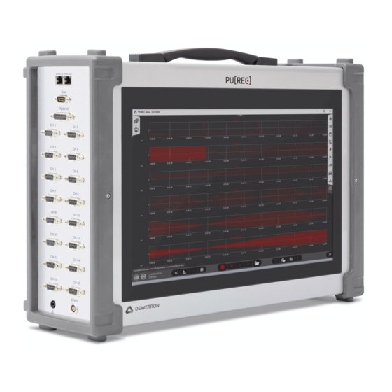
Page 19: Main System
Main System MAIN SYSTEM PU[REC] at a glance Power supply input connector Fold-out stand Power on/off push button 10 Intake vent and filter pad Dual LAN GBit connectors 11 SYNC-BUS Audio interface 12 Digital Input & Output connector 2x Display port, 1x HDMI 13 CAN connector (optional) 4x USB 3.1 GEN2 14 16x analog input... - Page 20 MAIN SYSTEM Power supply input connector 100 to 240 V (max. 90 to 264 V VOLTAGE 47 to 63 Hz FREQUENCY 300 W POWER Power on/off push button The power on/off push button at the front of the system is used to switch on the system. 2x GBit Ethernet connector The PU[REC] supports 10/100/1000 Dual LAN with standard RJ45 connectors.
- Page 21 MAIN SYSTEM 8 15.6" multi-touch display The PU[REC] is equipped with a bright 15.6" multi-touch panel (1920 x 1080 px) to control the instrument. Familiar gestures such as pinch and zoom are fully implemented within the operating system and will be described in chapter 'Operating with the touchscreen'.
- Page 22 MAIN SYSTEM Digital input & output connector (Digital I/O) Pin 1: DI1 / CNT1 Input_A Pin 9: DI2 / CNT1 Input_B 8 7 6 5 4 3 2 1 Pin 2: DI3 / CNT1 Input_Z Pin 10: DI4 / CNT2 Input_A Pin 3: DI5 / CNT2 Input_B Pin 11:...
-
Page 23: Block Diagram
MAIN SYSTEM Block diagram SYNC bus Display LVDS 16 channel PCIe x1 analog Gen2 Touch CNTRL with TEDS support HDMI Motherboard Display port Display port 4x USB 3.0 Audio 8x DI / 2x CNT ETH1 4x DO 1x CAN ETH2 System FAN COM1 EPAD... - Page 24 MAIN SYSTEM Notes 24 24...
-
Page 25: Signal Connection
MAIN SYSTEM Signal connection Direct voltage input CAUTION: Input is not isolated. Do not exceed ±12.5 V common mode voltage. Voltage <10 Voltage measurement D-SUB Isolated Sensor Simplified schematic Self-powered sensor CONNECTOR Mode Voltage Battery measurement Sensor with DIFF output Range 10 V GNDi... -
Page 26: Signal Connection Via Msi (Modular Smart Interface)
MAIN SYSTEM Potentiometric sensor Potentiometer D-SUB Simplified schematic PU[REC] CONNECTOR Sense+ Mode Voltage +5 V EXC EXC+ Range ±5 V GNDi GNDi EXC- -5 V EXC Sense- housing external solder bridge Signal connection via MSI (Modular Smart Interface) General MSI functionality Each MSI is a signal conditioner designed for a dedicated sensor type. -
Page 27: Voltage (<50 V) Via Msi-Br-V-200
MAIN SYSTEM Voltage (<50 V) via MSI-BR-V-200 MSI-BR-V-200 Sensor connection Input attenuation 50 ±0.5 % Input type Differential Rated input voltage to earth according to IEC/EN 61010-2-30 33 V , 70 V , 46.7 V Common mode voltage IN+ and IN-: -200 V to +180V Overvoltage protection ±250 V Input impedance IN+... -
Page 28: High Voltage Via Msi2-V-600
MAIN SYSTEM High voltage via MSI2-V-600 MSI2-V-600 Sensor connection 4 mm safety banana sockets Input attenuation 250 ±0.5 % Input type Differential Rated input voltage to earth according IEC/EN 61010-2-30 300 V CAT III / 600 V CAT II Common mode voltage ±1000 V Overvoltage protection 1500 V... -
Page 29: Strain Gauge Measurement Via Msi2-Stg
The signal is immediately amplified by a factor of 50. This reduces the impact of electromagnetic disturbances by the same factor. The maximum cable length between MSI and the PUREC is 50 meters. - Page 30 MAIN SYSTEM Jumper settings Quarter bridge Full bridge Half bridge 10 V 10 V 10 V 120 Ω 350 Ω 350 Ω Connecting a sensor EXC+ Sense+ Sense- EXC- Check the sensor datasheet and Prepare the sensor cable Connect the cable to the PCB; the determine the correct connection.
- Page 31 MAIN SYSTEM Full bridge 6-wire 10 V Strain gauge sensor MSI2-STG Simplified schematic PU[REC] Sense+ Mode Bridge +5 V EXC 120 Ω 350 Ω Range 10 mV/V EXC: -5 V EXC 10 V (±5 V) Sense- Housing Full bridge 4-wire 10 V MSI2-STG PU[REC]...
- Page 32 MAIN SYSTEM Quarter bridge 3-wire 10 V 120 Ω 350 Ω 350 Ω Strain gauge sensor MSI2-STG Simplified schematic PU[REC] Sense+ Mode Bridge +5 V EXC 120 Ω 350 Ω Range 10 mV/V EXC: -5 V EXC 10 V (±5 V) Sense- Housing 32 32...
-
Page 33: Iepe® Via Msi-Br-Acc
MAIN SYSTEM IEPE® via MSI-BR-ACC MSI-BR-ACC Input Range ± 10V Sensor Excitation 4 mA ±10 % Compliance voltage >23 V Accuracy 30 Hz to 30 kHz: 0.2 % Power consumption Max. 380 mW Input coupling AC 1.4 Hz Bandwidth 70 kHz limited by instrument Signal-to-noise ratio;... -
Page 34: Charge Via Msi2-Ch-X
MAIN SYSTEM Charge via MSI2-CH-x MSI2-CH-x Input Range MSI2-CH-5 ±5 000pC MSI2-CH-100 ±100 000pC Accuracy 3 Hz to 30 kHz: 0.5 % Gain drift 50 ppm/ °C Input coupling AC 0.14 Hz Bandwidth 70 kHz limited by instrument Signal-to-noise ratio; spurious-free SNR; Effective number of Bits;... -
Page 35: Thermocouple Via Msi2-Th-X
MAIN SYSTEM Thermocouple via MSI2-TH-x MSI2-TH-x Thermocouple types Type K, J, T, C Sensor connection 1m cable with standard miniature thermocouple connector according to TC type Preamplifier Integrated; cable drive capability 50 m Open thermocouple detection 100 MΩ pullup; broken sensor shows positive full scale CJC accuracy 1.0 °C Input impedance... - Page 36 That’s why the V2 series can be directly placed next to the sensor. Use extension cables up to 50 m between the MSI and the PUREC system instead of having long thermocouple lines with small signal level.
-
Page 37: Rtd Via Msi-Br-Rtd
MAIN SYSTEM RTD via MSI-BR-RTD > Support of Pt100, Pt200, Pt500, Pt1000, Pt2000 > 2-, 3- or 4 wire connection MSI-BR-RTD Supported sensors Resistance, Pt100, Pt200, Pt500, Pt1000, Pt2000 Temperature range -200 °C to 850 °C Constant current 1.25 mA Constant current accuracy ±0.02 % from calibrated value Constant current drift... - Page 38 MAIN SYSTEM RTD 4-wire sensor Pt100 MSI-BR-RTD PU[REC] +5 V Mode Temperature 4 mA Sensor type Pt100 -200 to 850 °C Range -328 to 1562 °F 1 kΩ -5 V RTD 3-wire sensor Pt100 MSI-BR-RTD PU[REC] +5 V Mode Temperature 4 mA Sensor type Pt100...
-
Page 39: Lvdt Via Msi2-Lvdt
MAIN SYSTEM LVDT via MSI2-LVDT MSI2-LVDT Transducer type LVDT with 5 or 6 electrical connections (wires) Sensor connection Soldering Excitation voltage Excitation frequency 2.5 kHz, 5 kHz, 18 kHz selectable by jumper (H, M, L; ±5 %) Output at stroke ends 280 mV/V to 1666 mV/V at full scale (+/-5 V), adjustable by gain-potentiometer Functional description The MSI2-LVDT is a high reliability conditioner for measurement of displacement with an LVDT (Linear Variable... - Page 40 MAIN SYSTEM LVDT MSI2-LVDT PU[REC] EXC1 2.5/5/18 kHz Mode LVDT EXC2 Range VA - VB VA + VB Gain Connecting a sensor Check the sensor datasheet and Prepare the sensor cable Solder the wires onto the printed determine the correct connection. circuit board.
-
Page 41: To 20 Ma Sensor Via Msi2-La-250R-20Ma
MAIN SYSTEM 4 to 20 mA sensor via MSI2-LA-250R-20mA > Direct connection of loop powered sensors > Simple connection without soldering MSI2-LA-250R-20mA Supported sensors: 4 to 20 mA; loop powered sensors Sensor connection: Push-in spring connection; 0.14 to 0.5 mm²; AWG 26 to 20 Input Range: ±25 mA accuracy:... -
Page 42: Operating With The Touchscreen
- Scrolls through recorded data (like scrolling with a mouse). - Drags the sidebar from the right side across the screen to open the channel setup Further information on how to operate with OXYGEN please find in the corresponding user manual available at: https://ccc.dewetron.com/pl/oxygen 42 42... -
Page 43: Oxygen Quickstart Guide
Perform a measurement and export the data in just a few easy steps! For a more detailed explanation of the OXYGEN software please refer to the OXYGEN Technical Reference Manual, which is available at https://ccc.dewetron.com/pl/oxygen or make sure to check out our latest PU[REC] videos on youtube available at https://www.youtube.com/playlist?list=PLySNf48JXZNjxKw8XI6YwlFmOoC-hJ4dz... - Page 44 MAIN SYSTEM Connect and set up signals and sensors It is possible to directly measure ±10 V or to use MSIs to expand the input signal possibilities. Open the Data Channel List by double clicking/tapping on the menu tab on the right side or by swiping it over the whole measurement screen, seen in Figure 2.
-
Page 45: Changing Channel Settings
MAIN SYSTEM Changing channel settings The next step is to change the channel settings. By simply clicking on the channel name in the list, a new name can be entered. Also, by clicking on the gear button the channel setting will open, seen in Figure 4. There different settings are available, like a sensor scaling if needed. -
Page 46: Record
MAIN SYSTEM Figure 6 Record To start the recording simply click on the record button. The red border and the REC indicator seen in Figure 7 in the lower left corner displays, that the recording is going on. Click on the Stop button to stop the recording. Figure 7 46 46... -
Page 47: Open Datafile And Export
MAIN SYSTEM Open Datafile and Export To open a datafile, click on the file button, and select the corresponding file (see Figure 8). The green border and PLAY indicator in the lower left corner indicate that a file is loaded for post-processing (see Figure 9). To export the data, click or tap on the Export Settings menu tab, select the desired format, channels to be exported and click on the export button seen in Figure 9. -
Page 48: Synchronization Options
The network topology is the responsibility of the customer. Any topology supported by the operating system can be used. In theory, the normal company network can also be used. However, DEWETRON recommends the use of a separate network which is only used for data transmission. -
Page 49: Cooling Considerations
MAIN SYSTEM Cooling considerations The intake vent of the PU[REC] is located at the bottom of the chassis, whereas the exhaust vent for the PU[REC] is at the right sidepanel of the chassis. CAUTION: Adequate clearance between the chassis and surrounding equipment or blockages must be maintained to ensure proper cooling of the internals of the chassis! PU[REC] front view hot air out... -
Page 50: Dimensions
MAIN SYSTEM Dimensions * Dimensions in mm (1 inch = 25.4 mm) 50 50... -
Page 51: Maintenance
Intervals may vary. Depending on environmental conditions, runtime, etc. DEWETRON offers various service and upgrade plans including cleaning/exchanging fans/power supply/CPU cooler (if required), BIOS, firmware and driver updates as well as reliabilty upgrades and full functionality check. Please do not hesitate to ask DEWETRON or your local distributor for further information and pricing. -
Page 52: Letter Of Volatility
MAIN SYSTEM Letter of volatility This describes the location and contents of volatile and non-volatile memory devices within the PU[REC]. Volatile memory Type Size User modifiable Function Process to delete 8 GB module Innodisk M4SI, DDR4 SODIMM Power OFF (16 x 512 MB chips) Intel i3 8100, cache 6 MB Cache... -
Page 53: Description Of Voltage Specifications
DESCRIPTION OF VOLTAGE SPECIFICATIONS Input ranges Like all measurement devices DEWETRON measurement equipment provides one or more 'Input ranges'. An 'input range' indicates the highest possible value which can be displayed, similar to the limit position of a dial instrument. -
Page 54: Common Mode Voltage
DESCRIPTION OF VOLTAGE SPECIFICATIONS If there is no measurement category specified, the measurement input is not appropriate to be applied to a public power grid. Examples: > Rated input 600 V CAT II: The measurement input can be connected to a public power grid within the category II as long as the voltage of the grid does not exceed 600 VRMS. -
Page 55: Max. Dc Voltage @Ac Coupling
DESCRIPTION OF VOLTAGE SPECIFICATIONS Max. DC voltage @AC coupling The given value refers to input AC coupled inputs only. 'Max. DC voltage @AC coupling' specifies the highest allowed direct voltage component on the measurement input, when the coupling mode is switched to 'Coupling AC'. Bus pin fault protection The specification 'Bus pin fault protection' refers to the wiring of bus systems (e.g. - Page 56 DESCRIPTION OF VOLTAGE SPECIFICATIONS Notes...
-
Page 57: Ce-Certificate Of Conformity
CE-Certificate of Conformity DEWETRON GmbH Manufacturer: Address: Parkring 4 8074 Grambach, Austria Tel.: +43 316 3070 0 Fax: +43 316 3070 90 e-mail: sales@dewetron.com http://www.dewetron.com Name of product: PU[REC] Data recorder Kind of product: The product meets the regulations of the following EC-directives: 2014/35/EU "Directive of the European Parliament and of the Council of 26 February 2014 on the... - Page 58 NOTES...
Need help?
Do you have a question about the PUREC and is the answer not in the manual?
Questions and answers