Table of Contents
Advertisement
Installation Manual
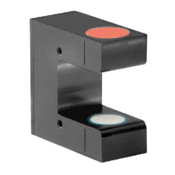
US01B.M8 / US04B.M8
Ultrasonic sensor for web guiding systems
Document Version
1.80
Issue Date / Author
02/2017 / NS
Diese Bedienungsanleitung ist auch in Deutsch erhältlich.
Bitte kontaktieren Sie Ihre nächstgelegene FMS Vertretung.
© by FMS Force Measuring Systems AG, CH-8154 Oberglatt – Alle Rechte vorbehalten.
Advertisement
Table of Contents

Related Manuals for FMS US01B.M8


Summary of Contents for FMS US01B.M8
- Page 1 Ultrasonic sensor for web guiding systems Document Version 1.80 Issue Date / Author 02/2017 / NS Diese Bedienungsanleitung ist auch in Deutsch erhältlich. Bitte kontaktieren Sie Ihre nächstgelegene FMS Vertretung. © by FMS Force Measuring Systems AG, CH-8154 Oberglatt – Alle Rechte vorbehalten.
-
Page 2: Table Of Contents
Installation manual US01B.M8 / US04B.M8 1 Table of contents TABLE OF CONTENTS ..........................2 SAFETY INSTRUCTIONS .......................... 3 Presentation of safety information ..................... 3 2.1.1 Danger that could result in minor or moderate injuries ..............3 ... -
Page 3: Safety Instructions
Installation manual US01B.M8 / US04B.M8 2 Safety instructions All safety related regulations, local codes and instructions that appear in the manual or on equipment must be observed to ensure personal safety and to prevent damage to the equipment connected to it. If equipment is used in a manner not specified by the manufacturer, the protection provided by the equipment may be impaired. -
Page 4: General Safety Information
Installation manual US01B.M8 / US04B.M8 2.2 General safety information The Material Sensors may not be stressed over the specification limits neither during assembly nor operation. The attachment points for the Sensors on the machine frame must be properly designed. The used mounting screws must be of the right size. -
Page 5: Product Information
Installation manual US01B.M8 / US04B.M8 3 Product information 3.1 System description The ultrasonic sensors can detect a very wide range of web materials including transparent films. The sensors are not suitable for sound permeable materials (e.g. net- like or open weave textiles). They are factory set and don’t need any adjustments or calibration. -
Page 6: Scope Of Delivery
Installation manual US01B.M8 / US04B.M8 Terms Position Description LED in plug Marking of center of sensor detection area Marking of center of sensor detection area Side of the ultrasonic transmitter Table 2: Terms 3.3 Scope of delivery 3.3.1 Included material sensor, installation manual 3.3.2 Not included... -
Page 7: Installation
(steering frame size, manual or motorized sensor adjustment, etc.). It is not part of supply and must be ordered separately. If the sensor is used with an integrated web guide controller within an FMS steering frame FMS-webMASTER, the sensor is connected with a cable 4x0.14mm of the respective length. -
Page 8: Operation
Installation manual US01B.M8 / US04B.M8 5 Operation 5.1 Denomination of the sensor position Left and right are always seen in direction of the running web. Figure 3: Terms on steering frames BKS_309.ai Terms Position Description Entry side Exit side Rolling direction... -
Page 9: Alignment Of The Sensor
Installation manual US01B.M8 / US04B.M8 5.2 Alignment of the sensor Figure 4: alignment of the sensor Terms sensor alignment Position Description Web edge Sensor axis Deviation of web edge to sensor axis Detection range of the sensor Marking for mid of detection area Table 4: Sensor alignment Loosen the fixing nut on the bracket and adjust the sensor. -
Page 10: Trouble Shooting
Installation manual US01B.M8 / US04B.M8 6 Trouble shooting Causes and possible solutions for errors Description of error Cause Corrective action Limited control range Edge has moved Adjust sensor more outside the sensor accurately to the center of detection range the measuring range. -
Page 11: Technical Data
Installation manual US01B.M8 / US04B.M8 7 Technical data Technical data Parameter US01B.M8 / US04B.M8 Detection range 8 mm [0.31”] Resolution 0.2 mm [0.007”] Measuring rate 2 ms Output signal 0 to 10 VDC 0V if detection area is fully covered... - Page 12 Installation manual US01B.M8 / US04B.M8 FMS Force Measuring FMS USA, Inc. FMS (UK) FMS Italy Systems AG 2155 Stonington Avenue Highfield, Atch Lench Via Baranzate 67 Aspstrasse 6 Suite 119 Road 8154 Oberglatt Hoffman Estates,, IL Church Lench 20026 Novate...
Need help?
Do you have a question about the US01B.M8 and is the answer not in the manual?
Questions and answers
Where can I buy the FMS US01b M8 sensor