
Subscribe to Our Youtube Channel
Related Manuals for Oxford Instruments ANDOR Clara


Summary of Contents for Oxford Instruments ANDOR Clara
- Page 1 Clara Version 2.0 rev 24 Mar 2015 Hardware Guide andor.com © Andor Technology 2015...
-
Page 2: Table Of Contents
Clara CONTENTS SECTION 1: INTRODUCTION ......................7 HELP AND TECHNICAL SUPPORT ..................7 DISCLAIMER ..........................9 TRADEMARKS AND PATENT INFORMATION ................ 9 COMPONENTS ........................10 1.4.1 .................... 10 ptiOnal ccessOries SECTION 2: PRODUCT OVERVIEW ....................11 FRONT VIEW ........................2.1.1 ccD s ...................... - Page 3 Clara SECTION 4: OPERATION ........................17 EMERGENCY MAINS DISCONNECTION ................17 POWER-UP SEQUENCE ......................17 POWER-DOWN SEQUENCE ....................17 RISK MITIGATION ........................17 4.4.1 ..................... 17 echanical Ousings 4.4.2 ..............17 azarDs ue tO Oisture Or iquiDs USING THE CLARA ........................ 18 4.5.1 ccD s .................
- Page 4 Clara SECTION 7: SPECIFICATIONS ......................26 CAMERA TECHNICAL SPECIFICATIONS ................26 CAMERA ..........................26 ENVIRONMENTAL ....................... 27 APPENDIX A: GLOSSARY ........................ 28 APPENDIX B: MECHANICAL DRAWINGS ..................38 APPENDIX C: OTHER INFORMATION ..................... 39 Version 2.0 rev 24 Mar 2015...
- Page 5 Before using the system, please follow and adhere to all warnings, safety, manual handling and operating instructions located either on the product or in this manual The Andor Clara is a precision scientific instrument containing fragile components. Always handle with care Do not expose the product to extreme hot or cold temperatures...
- Page 6 Clara evision istoRy Version Released Description 25 Oct 2011 Initial Release Presentation enhanced and minor edits throughout (all sections). Improved description of camera hardware (Section 2) Removal of Solis software content- obsolete replicated information. This is covered in full in the 24 Mar 2015 Solis in-application help.
-
Page 7: Section 1: Introduction
Introduction SECTION 1: INTRODUCTION Thank you for choosing the Andor Clara. Andor’s CCD (Charge Coupled Device) exploits the processing power of today’s desk-top computers. USB 2.0 connectivity ensures a seamless interface with the camera, as well as generating and receiving the signals you use to work with most stanadrd pulsed sources. From the outset, the Clara has been designed for ease of use. - Page 8 Clara Introduction If you have any questions regarding the use of this equipment, please contact the representative* from whom your system was purchased, or: Europe Andor Technology Andor Technology 7 Millennium Way 425 Sullivan Avenue Springvale Business Park Suite # 3 Belfast South Windsor BT12 7AL...
-
Page 9: Disclaimer
Andor, the Andor logo and Solis are trademarks of Andor Technology. Andor is an Oxford Instruments company. All other marks are property of their owners. Changes are periodically made to the product and these will be incorporated into new editions of the manual. -
Page 10: Components
Clara Introduction 1.4 C omponents The standard components supplied with the Clara are shown in Table 1: Table 1: Standard Components supplied with the Clara Description Quantity Clara Interline CCD Camera Description Quantity 1 x 3 m USB 2.0 Cable Power Supply Unit (PS12) and Country specific... -
Page 11: Section 2: Product Overview
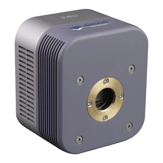
Clara PRODUCT OVERVIEW SECTION 2: PRODUCT OVERVIEW This section provides an overview of the hardware and main features of the Clara. Further technical information is outlined in the Appendix A of this manual. 2.1 f Ront Cooling slots Camera Window CCD Sensor C-mount Figure 2: Clara Front View... -
Page 12: Rear Panel
Clara PRODUCT OVERVIEW 2.2 R eaR panel USB 2.0 Connection Power Input Power Switch Cooling Fan Multi I/O Timing Cable Connection Figure 3: Clara Rear Plate Connections 2.2.1 usB 2.0 C onneCtion For connection of the Clara to the control PC. 2.2.2 C ooling A cooling fan draws heat from the CCD Sensor. -
Page 13: Ower Nput
Clara PRODUCT OVERVIEW Table 2: Multi I/O Timing Cable Pinouts 26-way D type connector External Trigger I/O data bit 4 Trigger Invert Input I/O data bit 5 I/O data bit 6 OutputDAC1 I/O data bit 7 OutputDAC2 +5V Output Frame Readout Fire C Data Interline Shift... -
Page 14: Ower Onnection In Outs
Clara PRODUCT OVERVIEW The Clara PSU is for use with Telecommunications, Computer, Industrial Controller, and OA Systems and must only be used indoors The Clara requires a Direct Current (DC) supply. The electrical mains lead should be certified for use in your country and in applicable countries the plug must be fitted with a 240V 5A fuse. -
Page 15: Section 3: Installation
Clara INSTALLATION SECTION 3: INSTALLATION 3.1 s afety onsideRations • Prior to commencing installation, please refer to the Safety and Warning Information at the preface of the manual and the Specifications in Section 7 to ensure all requirements have been met. •... -
Page 16: System Connection
Clara INSTALLATION 3.4 s ystem onneCtion Connect the elements of your system in the sequence that follows: • Power up the PC • Connect the USB cable between the USB connection on the rear plate and any available USB 2.0 port on the •... -
Page 17: Section 4: Operation
Clara OPERATION SECTION 4: OPERATION WARNINGS: • IF THE EQUIPMENT IS USED IN A MANNER NOT SPECIFIED BY ANDOR OR ITS DISTRIBUTORS, THE PROTECTION PROVIDED BY THE EQUIPMENT MAY BE IMPAIRED. • READ THE USER GUIDES SUPPLIED WITH YOUR SYSTEM COMPONENTS AND CONTROL SOFTWARE PRIOR TO USE. -
Page 18: Using The Clara
Clara OPERATION 4.5 u sing tHe laRa • The Clara is controlled through the control software, for example Solis. Please refer to your Solis Software Guide for the latest and complete guide to using Solis. • The following information provides additional information specific to the Clara 4.5.1 CCd s etup ptions foR tHe... -
Page 19: E Xtended Ir M Ode
Clara OPERATION Certain text boxes become active as you select each Acquisition Mode. Minimum default values are also shown in the text boxes. NOTE: The value you enter in one text box may affect the minimum permissible value in another text box. -
Page 20: O Utput Dac S
Clara OPERATION 4.5.4 o utput Voltages to control external devices from the Clara can be chosen by selecting the Output DACs function from the Hardware drop-down menu. • These DAC outputs allow the user to set an analogue voltage up for external devices. •... -
Page 21: T Ime To O Pen Or C Lose
Clara OPERATION In Permanently OPEN mode, the shutter will be open before, during and after any data acquisition. • • Permanently CLOSED mode can be useful if you want to take a series of acquisitions in darkness and do not require the shutter to open between acquisitions. You might, for example, wish to capture a sequence of background values. -
Page 22: E Xposure T Ime
Clara OPERATION Let us look at the STT in the context of the Andor system. By default, the value you enter in the Exposure Time text box in the Setup Acquisition dialog box determines the length of time the shutter will be in the open state. However, to accommodate the STT, the rising edge of the shutter output is sent before the FIRE output signal by an amount equal to the STT. -
Page 23: Ccumulate Ycle Ime Of Ccumulations
Clara OPERATION 4.6.4 a & n CCumulate yCle CCumulations If you have selected Accumulate or Kinetic as the acquisition mode, with Internal triggering, you can also select the Accumulation Cycle Time and No. of Accumulations. The Accumulation Cycle Time is the period in seconds between each of a number of scans, whose data are to be added together in computer memory to form an Accumulated Scan. -
Page 24: Section 5: Maintenance
Clara MAINTENANCE SECTION 5: MAINTENANCE THERE ARE NO USER-SERVICEABLE PARTS INSIDE THE CAMERA. DAMAGE CAUSED BY UNAUTHORISED MAINTENANCE OR PROCEDURES WILL INVALIDATE THE WARRANTY. 5.1 C leaning and eContamination The most critical aspect of maintenance by the user is to ensure that the system is in a clean environment that is suitable for sensitive electro-optical equipment. -
Page 25: Section 6: Troubleshooting
Clara TROUBLESHOOTING SECTION 6: TROUBLESHOOTING This section provides useful information and solutions for some troubleshooting scenarios. If you have an issue that you are unable to rectify using this section, please contact Andor Technical Support for further advice. 6.1 C ameRa BuzzeR does not sound on staRt The camera buzzer should be audible momentarily when the camera is switched on. -
Page 26: Section 7: Specifications
Clara SPECIFICATIONS SECTION 7: SPECIFICATIONS 7.1 C ameRa eCHniCal peCifiCations Clara Clara E Active pixels [W x H] 1392 x 1040 Pixel size 6.45 x 6.45 μm Image area [W x H] 8.98 x 6.71 mm Pixel readout rate (MHz) 20, 10, 1 Read noise (e-) Typical 1 MHz... -
Page 27: Environmental
Clara SPECIFICATIONS 7.3 e nviRonmental Usage Indoor use only Altitude Up to 2000 m Operating Temperature 0°C to 30°C ambient Storage Temperature -25°C to 50°C Operating Relative Humidity <70% (non-condensing) Overvoltage Category CAT II. An overvoltage category of CAT II means that the equipment is designed to cope with transient voltages above the rated supply that would be experienced by any product connected to a mains socket in a building. -
Page 28: Appendix A: Glossary
Clara GLOSSARY APPENDIX A: GLOSSARY If this is the first time you have used Andor’s CCD, the glossary that follows will help familiarize you with its design philosophy and some of its key terminology. A Charge Coupled Device (CCD) is a silicon-based semiconductor chip bearing a two-dimensional matrix of photo- sensors, or pixels. - Page 29 Clara GLOSSARY Readout Sequence of a CCD In the course of readout, charge is moved vertically into the shift register, and then horizontally from the shift register into the output node of the amplifier. The readout sequence illustrated below (which corresponds to the default setting of the Full Resolution Image binning pattern) allows data to be recorded for each individual element on the CCD-chip.
- Page 30 Clara GLOSSARY Interline CCD An Interline CCD is designed to compensate for some of the shortcomings of standard Frame Transfer (FT) CCD’s. Instead of having a storage area of similar dimensions directly below the active region, an interline sensor has optically masked columns of pixels adjacent to each active column.
- Page 31 Clara GLOSSARY Accumulation Accumulation is the process by which data that have been acquired from a number of similar scans are added together in computer memory. This results in improved signal to noise ratio. Acquisition An Acquisition is taken to be the complete data capture process. A/D Conversion Charge from the CCD is initially read as an analog signal, ranging from zero to the saturation value.
- Page 32 Clara GLOSSARY Vertical Binning In Vertical Binning, charge from two or more rows of the CCD-chip is moved down into the shift register before the charge is read out. The number of rows shifted depends on the binning pattern you have selected. Thus, for each column of the CCD-chip, charge from two or more vertical elements is ‘summed’...
- Page 33 Clara GLOSSARY Horizontal Binning (Creating Superpixels) Shifting the charge horizontally from several pixels at a time into the output node is known as horizontal binning. Horizontal binning in combination with vertical binning allows you to define so-called superpixels that in Image Display Mode represent as a single picture element charge that has been binned from a group of pixels.
- Page 34 Clara GLOSSARY Counts Counts refer to the digitization by the A/D conversion and are the basic unit in which data are displayed and processed. Depending on the particular version of the detection device, one count may, for example, be equated with a charge of 10 photoelectrons on a pixel of the CCD.
- Page 35 Clara GLOSSARY Noise Noise is a complex topic, the full exploration of which is beyond the scope of this glossary. Noise may, however, be broken down into two broad categories as follows: • Pixel Noise • Fixed Pattern Noise These two categories are described in the paragraphs that follow. Pixel Noise Let us first attempt to define pixel noise.
- Page 36 Clara GLOSSARY Shot Noise Shot Noise is due to basic physical laws and cannot be removed. Any signal, whether it is a dark signal or a light signal, will have shot noise associated with it. This is most simply defined as: If the signal or dark signal = N electrons, the shot noise is the square root of N.
- Page 37 Clara GLOSSARY Scan Types: Keep Clean & Acquired The CCD is continually being ‘scanned’ to prevent its becoming saturated with dark current (see dark signal). If the Scan is being used simply to ‘clean’ the CCD (i.e. it is a keep-clean scan), the charge from the CCD is discarded. In an acquired scan, however, the charge undergoes A/D conversion and is acquired into computer memory so that it can be used for subsequent processing and display: it is ‘read out’...
-
Page 38: Appendix B: Mechanical Drawings
Clara MECHANICAL DRAWINGS APPENDIX B: MECHANICAL DRAWINGS Dimensions in mm [inches] Front and side view Mounting Hole locations Focal Plane Distance Version 2.0 rev 24 Mar 2015... -
Page 39: Appendix C: Other Information
Clara OTHER INFORMATION APPENDIX C: OTHER INFORMATION Terms and Conditions of Sale and Warranty Information The terms and conditions of sale, including warranty conditions, will have been made available during the ordering process. The current version may be viewed at: http://www.andor.com/pdfs/literature/Andor_Standard_Warranty.pdf Waste Electronic and Electrical Equipment Regulations 2006 (WEEE) The company’s statement on the disposal of WEEE can be found in the Terms and Conditions.
Need help?
Do you have a question about the ANDOR Clara and is the answer not in the manual?
Questions and answers