
Subscribe to Our Youtube Channel
Related Manuals for Gorgy Timing LEDI NETWORK TDS V1


Summary of Contents for Gorgy Timing LEDI NETWORK TDS V1
- Page 1 ® LEDI NETWORK LEDI ® NETWORK TDS GPS RAIL DIN TH35 TIME SERVER USER MANUAL MDE-LEDI-NETWORK-TDS-4099V2.0...
- Page 2 ® NETWORK TDS as far as possible from sources of radiation (Loudspeakers, antennas, high-frequency equipment, electromagnetic alarms…). Gorgy Timing disclaims all liability in the event of accident or damage caused by ® improper use of LEDI NETWORK TDS. All GORGY TIMING products comply with the following standards: CE, EN60950-1, EN55022 class B, EN50024.
- Page 3 EXPLANATION OF SAFETY SIGNS ON THE PRODUCT General hazard – there is a risk of damage to the product if instructions are not followed Electrical hazard – there is a risk of electrocution or personal injury if instructions are not followed.
-
Page 4: Table Of Contents
CONTENTS CONTENTS .......................... 4 INTRODUCTION......................7 1.1. LEDI ® NETWORK TDS V1 RACK ..................7 1.2. LEDI ® NETWORK TDS GPS – RAIL DIN TH35..............9 1.2.1. Version < 100m cable (solution with antenna GPS converter Part Number: 3Gxx) 10 1.2.2. - Page 5 4.5.2. Menu ........................28 4.5.3. IPv29 ........................29 4.5.4. IPv6 ........................31 4.6. RESTARTING ........................ 33 WEB INTERFACE ....................34 5.1. PRESENTATION ......................34 5.2. DESCRIPTION OF WEB PAGES ..................35 5.2.1. Navigation menu ....................35 5.2.2. "Index" Page ......................38 5.2.3.
- Page 6 7.1. AFNOR/IRIG-B NFS87500 ....................87 7.2. DESCRIPTION OF DCF AND TDF TIME CODES ............90 7.3. POLARISED MINUTE PULSES ..................92 APPENDIX C – MAINTENANCE ................94 8.1. CARD REPLACEMENT + IMPULSION CARD POWER SUPPLY ........94 8.2. MICROCONTROLLERS REPLACEMENT ............... 95 8.3.
-
Page 7: Introduction
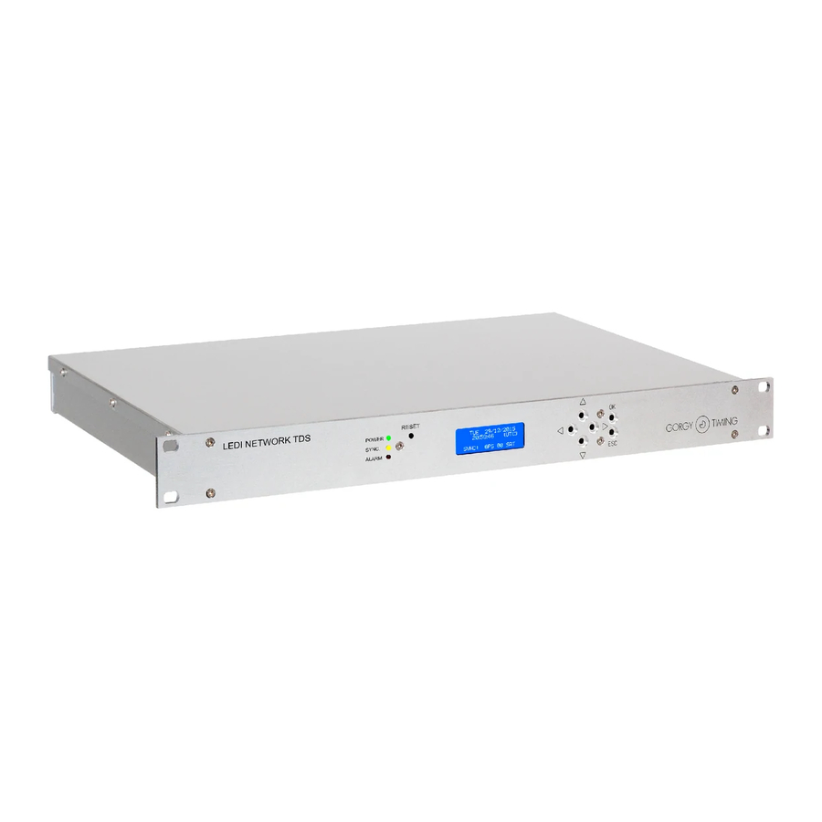
► SNMP v1, v2c, v3 ► (S)NTP ► Telnet ► ENDMI (to detect Gorgy Timing ► products on the IP network) Security features ensure that the server delivers reliable and continuous timing information. ® 1.1. LEDI NETWORK TDS V1 RACK The server synchronises through an NTP Ethernet 10/100 base T or DCF or GPS time input. - Page 8 The use of the LEDI ® Network TDS V1 has several advantages: ► Ethernet + IP network interfacing. ► Simplified installation. ► Easy remote configuration and diagnostics. ► 1U 19” rack easily mounted in many installations. ► 3 configurable outputs: AFNOR NFS 87500 / IRIG-B NTP (V2, V3, V4): Unicast, Multicast et Broadcast Minute Impulses 24V //...
-
Page 9: Ledi ® Network Tds Gps - Rail Din Th35
NETWORK TDS GPS – RAIL DIN TH35 ® 1.2. LEDI The time server has GPS synchronisation input providing SNMP supervised NTP time synchronisation. Both an alarm visible on the front LED display and quick configuration from the front panel buttons are available. 209 x 73 x 136 mm (WxHxD) MDE-LEDI-NETWORK-TDS-4099V3.0... -
Page 10: Version < 100M Cable (Solution With Antenna Gps Converter Part Number: 3Gxx)
1.2.1. Version < 100m cable (solution with antenna GPS converter Part Number: 3Gxx) MOUNTING Fixing by rear panel in Rail Din (see image below). ► Kit contents (cable and GPS antenna not included): ® LEDI Network TDS Rail Din One RJ45 network cable A DVD containing software and documentation ☛... - Page 11 ► Contents of kit (cable and RTB GPS antenna not included): LEDI ® Network TDS Rail Din (RTB GPS), One RJ45 network cable A DVD containing software and documentation ☛ Please contact customer service if an item is missing ► Power supply: Continuous power supply 24Vdc (18-72Vdc) on screw terminal block –...
-
Page 12: Rtb Gps Antenna (Part Number: Rtbgps-4080)
A. RTB GPS antenna (part number: RTBGPS-4080) The RTB GPS generator is a GPS (Global Positioning System) satellite system receiver device delivering time in IRIG B or AFNOR NFS 87500 code. MDE-LEDI-NETWORK-TDS-4099V3.0... -
Page 13: Quickstart
QUICKSTART 2.1. PRODUCT CONNECTION It is strongly recommended to make a note of the serial number (written on the identification label), the location and a brief description of the device. The table in Appendix A - 6.1 Installation View can be used for this purpose. ►... -
Page 14: Manual Network Configuration
2.2. MANUAL NETWORK CONFIGURATION In the case of an NTP input, local time outputs and/or specific configurations of time outputs, ® LEDI Network TDS server configuration is required to synchronise equipment. By default, the server is configured to obtain its IP addresses (v4 and v6) on a DHCP server. There are several ways in which the IPv4 and IPv6 configurations can be manually modified: ►... -
Page 15: General Information
3. GENERAL INFORMATION ® This section introduces the basic concepts of the LEDI Network TDS. It can help you to understand the functioning of the product in various circumstances. ® The LEDI Network TDS contains firmware that manages the time flow in the product and the user interfaces. -
Page 16: Leap Second
3.2. LEAP SECOND 3.2.1. Definitions What is a leap second, what is its purpose, when does it occur? Find answers here: https://en.wikipedia.org/wiki/Leap_second 3.2.2. Protocols incorporating a leap second NTP, DCF, TDF and IRIG-B IEEE 1344 protocols include a field in their messages to indicate that a leap second will occur. -
Page 17: Configuration Recommendations
3.2.4. Configuration recommendations To comply with legal time, if there is no indicator on the time input of an LEDI Network TDS, ® check in the latest IERS Bulletin C if a leap second will be inserted in June or December at least one month in advance and configure the manual indicator on this product accordingly. -
Page 18: Notions Of The Ntp Protocol
(128-bit MD5 hash) of the packet (see section 5.2.6. "NTP" page). In addition to the NTP client software for Windows issued by Gorgy Timing (Gt Synchro), other NTP client software for various devices can be found at www.ntp.org/software. -
Page 19: Client/Server Mode
3.4.1 Client/Server mode This mode is the most widely used as it is compatible with conventional network infrastructures and is highly accurate. The client regularly evaluates the current offset in relation to its servers. This measurement is done using a message exchange mechanism as shown in the following diagram: When the data contained in the server response and the time of receipt, the NTP client calculates the offset of its clock by subtracting the server date from its clock to compensate for transmission delays. -
Page 20: Broadcast Mode
Depending on the client software, the accuracy provided can be close to a few tens of microseconds. For added security, clients can be configured to use a different secret key for each server. 3.4.2. Broadcast mode An NTP server configured in broadcast mode regularly sends an NTP packet to a configurable IP address. -
Page 21: Snmp (Simple Network Management Protocol) And Mib (Management Information Base)
Here are the meanings of the different states: ► Initial: The time server has just started up. ► Synchronising: The time input is valid. The time server has selected it. It is waiting until the time information is sufficiently accurate and propagated on the server before activating its time output. - Page 22 Thus each element in the tree structure (folder, table or variable) can be identified by a sequence of names and/or numbers called OID (Object Identifier) e.g. the folder containing all the variables specific to Gorgy Timing products identified "iso.org.dod.internet.private.enterprises.gorgy",...
-
Page 23: Time Input Instability Detection
The tables can be considered as files containing only variables. To raise an SNMP query, you must give an OID variable followed by “.0” if the variable is not in the table, otherwise the input index must be given in the table. There are several possible forms of query: ►... -
Page 24: Front Lcd Display
FRONT LCD DISPLAY 4.1. LIGHTS AND BUTTONS The front panel display can show 4 lines of up to 20 characters each. There are 6 buttons which are used to navigate through the menus and to change the IPv4/IPv6 settings (see section 4.5.2. -
Page 25: Startup
4.2. STARTUP During start-up, the LCD screen displays the message "Init..." until the embedded software starts and shows the loading status of the different software modules: The firmware version is displayed on the second line whilst it is loading. 4.3. TIME DISPLAY Normal operating: ►... -
Page 26: Alarm Display
This status may occur temporarily during initialisation and in normal operation. If the fault persists and the corresponding outputs no longer emit time codes, please contact Gorgy Timing Customer Service. ► SERVER LOCKED: the time outputs have been disabled by a user. - Page 27 ► WAITING SAT INFO: the satellite synchronisation module expects certain information from the system constellation (almanacs). This message should disappear after a few minutes. When an alarm with a long description occurs, it is displayed across the entire screen. The following is a list of possible long description alarm messages: The main ethernet interface of the time server is writing in flash.
-
Page 28: Ipv4 / Ipv6 Configuration
4.5. IPV4 / IPV6 CONFIGURATION The blue LCD screen and the buttons can be used to manually set up the IP settings of the LEDI ® NETWORK TDS. 4.5.1. Display current IP addresses ► Press any of the arrow keys to bring up a screen showing the IP addresses of the LEDI ®... -
Page 29: Ipv29
4.5.3. IPv29 The below diagram describes the IPv4 configuration menus tree. An explanatory paragraph is provided after the diagram. ► Step Use the direction keys “ ↑ ” and “ ↓ ” to switch between Static and DHCP mode. Use the “... - Page 30 ► Step 2 ► Static mode: This menu allows you to set up: The IPv4 address (IP field), The sub-mask (MASK field) The network gate (GATE field). The field being modified flashes on the screen. Use the “ ↑ ” and “ ↓ ” arrow keys to change the field value. “...
-
Page 31: Ipv6
4.5.4. IPv6 The below diagram describes the IPv6 configuration menus tree. An explanatory paragraph is provided after the diagram. MDE-LEDI-NETWORK-TDS-4099V3.0... - Page 32 ► Step 1 Use the “ ↑ ” and “ ↓ ” arrow keys to switch between Static and DHCPv6 mode, Use the “ESC” key to return to the previous menu. Use the “OK” key to validate the selection and more on to step 2. ►...
-
Page 33: Restarting
4.6. RESTARTING ► Press “OK” on this page to reboot the LEDI ® Network TDS. MDE-LEDI-NETWORK-TDS-4099V3.0... -
Page 34: Web Interface
5. WEB INTERFACE 5.1. PRESENTATION ® The LEDI NETWORK TDS can be configured and supervised through a WEB interface (website composed of several pages). This is accessible in http or https depending on the configuration of the time server. ® https LEDI Network... -
Page 35: Description Of Web
5.2. DESCRIPTION OF WEB PAGES 5.2.1. Navigation menu When accessing the web interface, the “Index” page is displayed. On the left, you will see a navigation menu which displays the different pages. Index: General information about the product and quick disabling of the outputs. - Page 36 Each time that this icon: is shown, it means that the user can hover over the icon with the mouse for more information about the field in question. With the exception of the index page, access to all pages is restricted.
- Page 37 ► From NTPServ 2.00 firmware release including 17.292: The “Restart” button is available on Web pages with settings requiring the server to be restarted when modified. After clicking “Save Settings”, the message “Warning! A reboot is required to apply some appears above the “Save Settings”...
-
Page 38: Index" Page
Product name ► Displays the server name. ► Serial number ► Displays the GORGY TIMING serial number of the product. It is a 6-digit number identical to the one labelled on the bottom or back of the product. Up Time ► Total running time of the Ethernet interface since it was last reset. The ►... - Page 39 System ► MAC Address ► Medium Access address of the Ethernet interface. ► Firmware version ► Current version of the firmware embedded in the Ethernet module. Always starts with “2.00 release”. The first number corresponds to the year and the second to the day of the year of the firmware release date.
-
Page 40: Network" Page
► Locked server: Degraded status. The server has detected a time gap superior to the authorised threshold on its synchronising input, or the status was forced by clicking “Lock the server now”. In this state, the server no longer delivers synchronisation time output codes. - Page 41 ► Address from DHCP server ® If this box is checked, the LEDI NETWORK TDS will attempt to get an IPv4 address from a DHCP server at startup. Failure to obtain an address this way will result in the server using its automatically configured address. By unchecking the box, the following settings become available: ►...
- Page 42 The first section displays the current status, while the second section is used to configure the settings: ► Address from DHCP server If this box is checked, the LEDI ® NETWORK TDS will attempt to get an IPv6 address from a DHCP server at start-up.
-
Page 43: Alarms" Page
► DHCP client identifier: This field can contain a customisable DHCP ID. The value is inserted as an argument of DHCP option 61 in DHCP requests sent to the server. Your DHCP server can then store the ID/IP address pair to reserve this IP address and redistribute it when the same ID is provided. - Page 44 E-Mail alerts Management Use this part of the Web page to set up the device supervision to send event logs by e-mail. If “Enable email alerts” is checked when an event/alarm is triggered, the LEDI ® Network TDS will send an email to the SMTP server port by authenticating as configured here. The SMTP server address can be a DNS name or an IP address.
-
Page 45: Snmp" Page
Events / Alarms table Use this part of the Web page to configure filter settings for two features for sending event logs. Use this table to choose which events trigger logging on the SD card and/or sending an e- mail. 5.2.5. - Page 46 System information ► The three fields Name, Location and Contact can be individually filled in to provide Network TDS in the variables “sysContact”, “sysName” and ® information about the LEDI “sysLocation” of the classic .iso.org.dod.internet.mgmt.mib-2.system branch. ► Use the community field for SNMP versions 1 and 2c. The community of the SNMP client connecting to the server must match this field for the server to respond to the request.
- Page 47 ► If you want to use the SNMPv3 protocol features, simply enter a username in the Username fields. ► Filling in the Password field automatically activates the password check on incoming SNMPv3 requests. Then the server will only respond to the requests with valid credentials.
-
Page 48: Ntp" Page
5.2.6. "NTP" Page The NTP page shows the synchronisation mode used by the server or the mode selected by the NTP software. It also shows the NTP servers defined by the user. “NTP Server” Section Use this section to manage the settings of the NTP server. MDE-LEDI-NETWORK-TDS-4099V3.0... - Page 49 Enable NTP Server ► If this box is not checked, the server will not respond to any NTP requests. Reference ID ► This field shows the current “Reference Identifier” used in NTP messages. This field is automatically computed depending on the LEDI ®...
- Page 50 NTP Server statistics ► Enable NTP statistics logging Checking this box allows a log to be recorded each time an NTP request arrives at the server. The list of clients can be consulted on another page by clicking on the “View NTP statistics”...
- Page 51 "NTP Client" Section If the option is installed, the LEDI ® NETWORK TDS can synchronise with up to 5 NTP servers. The NTP client actually sends requests to only one server at a time, but it is able to automatically switch to another server in case the one it is using stops responding or does not send enough responses.
- Page 52 Client mode ► The NTP client sends queries to all servers one by one according to their position in the list. The NTP client therefore first sends a query to the server at the top of the list at start- up.
- Page 53 Number of queries sent by the server since the NTP NTP requests sent client was activated. Number of responses received by the server from the Received answers contacted NTP server. Data about the period during which the embedded NTP Last Sync client correctly contacted the distant server.
-
Page 54: Ntp Server Statistics Page
Use the DSCP (Differentiated Services Code Point) field to enable service differentiation. Please see RFC 24741 for more information. When this box is checked, the 1-byte the Type of Service (ToS) field in NTP packets is replaced by the DS field. The first 6 bits (DSCP) of the DS field are then configurable here. 5.2.7. -
Page 55: Input" Page
5.2.8. "Input" Page The input page regroups information and settings about the time base and the time input ® available on the LEDI Network TDS. Time Base State ► This field provides information about the type of oscillator and the current accuracy of ®... - Page 56 ► Modify internal time Checking this box allows you to modify and force the internal time on the system when it is in “Free Running” mode. The internal time and date will be displayed in UTC. For example, if the local time in France is 20:59:00 on 01/02/2010, enter 19:59:00 on 01/02/2010 to get the UTC time (one hour earlier as France is UTC+1, DST OFF at this time of year).
- Page 57 Description of available information and settings ► The table below shows the available features depending on the type of synchronisation input. DCF/GPS Series of fixed characters including the type of synchronisation (DCF or NTP). The Type GPS antenna transmits from the DCF. Time offset between...
- Page 58 Options Maximum autonomy when synchronization is lost ► If the time source is lost, the server can function autonomously. When the autonomy time is exhausted, the server stops providing time to its outputs. The autonomous operation time can be set here or replaced by “-1”, “disable” or an empty field to disable the autonomy limit.
-
Page 59: Output" Page
► Input Leap Indicator ➔ Gives the status of the leap second indicator derived from the synchronisation input. ► Output Leap Indicator ➔ Gives the status of the leap second indicator sent from the time outputs. 5.2.9. "Output" page ® This page shows the output cards detected on the LEDI NETWORK TDS and allows them to be configured one by one. - Page 60 In case of no internal communication with the output card, the front screen displays the message “Output Alarm!”. If this issue persists over time or after restarting the device, please contact Gorgy Timing Customer Service. The previous image shows the configuration page of a 4 IRIG output card. It contains information common to all the output cards: its address (internal to the rack), its type and its firmware version (here the 4/1350 version of the 4AFN firmware).
- Page 61 CARTE Effects The output card will no longer respond to NTP requests. IRIG The 1kHz carrier will be present but will no longer be modulated. POLAR PULSE Polarised impulses will no longer be generated. UTC (Time zone) ► Under normal operating conditions, the unit’s internal time is UTC. In order to send the local time on the outputs, it is necessary to first apply an offset to UTC.
- Page 62 Specific options Certain output cards have their own specific configuration options. AFNOR/IRIG-B Choose your output time zone and frame format: AFNOR NFS 87500, IRIG-B 122, IRIG-B 123, IEEE 1344 or IEEE 1344 + binary second. The ports of the NTP output cards integrate the same network interfaces (minus the NTP client) as the management port on their own network interfaces.
- Page 63 POLAR PULSE ► Alarm: alarm indicator (power, open serial circuit, parallel short-circuit). ► Output time: displaying the time sent to impulsion clocks. ► Period: impulsion selections every 30 or 60 seconds. ► Impulsion Duration: adjustment of the impulsion duration in quarters of a second. ►...
-
Page 64: Interface" Page
► Uncheck the “Disable the output card” box and press “Save Settings” to start the pulse generation in high-speed (1 pulse every 2 seconds) or put it on hold if the time catchup is too long (this time depends on the format and the 30 or 60 second mode). High-speed (or standby) will be automatically stopped when the distributed time is equal to the time base shown on the front panel display and corrected for any local time offset. -
Page 65: Front Lcd
B. Front LCD Local time on front LCD ► Checking this box displays the local time on the front panel, otherwise it displays UTC time. If this box is checked, the time zones must be set. See chapter 3.1. Time Zones for more information on the operation of time zones. -
Page 66: Other Interfaces
C. Other interfaces HTTP(S) support ► Use this page to restrict access to the Web page to HTTP requests only, HTTPS requests only, or both. Users can provide their own security certificates for HTTPS. To do this, two ssl.cert and ssl.key files must be placed in the .cfg folder at the root of the embedded file system accessible via FTP or SCP. - Page 67 Enable Telnet console ► Disables the Telnet server if unchecked. The Telnet interface is described in section F. Telnet interface and SSH in section 5.2.10. “Interface” page. SSH Support ► Enables/disables password and/or username access to the SSH server. The SSH interface is described in section F.
-
Page 68: File System
D. File system Files can be exchanged via FTP and SCP with the following Ethernet interfaces: ► ® LEDI Network TDS management and ► NTP output On each Ethernet interface the storage space is limited to 1472kb. The files are stored even if the power is switched off. -
Page 69: Snmp Interface
OID iso.org.dod.internet.private.enterprises.gorgy.software.ntpRangeProduct. All information from the classic branch “.iso.org.dod.internet.mgmt.mib-2” is also available for Gorgy Timing products. Among this information, the variables “sysContact”, “sysName” and “sysLocation” in the “system” folder can be configured on the product via the other user interfaces (website, Telnet and SSH). -
Page 70: Telnet And Ssh Interface
To change a setting, the user must first change the relevant fields and then set the applyXXXXXSettings variable (where XXXXX is the name of the setting group) to 1. No changes will be applied to the unit configuration until the user activates the relevant indicator. - Page 71 ► Under Windows To connect to a Gorgy Timing product via Telnet, run cmd.exe and enter “telnet <IP> 9999” replacing <IP> with the IP address of the product. For the SSH protocol, there is no application included in Windows. You will need to install a client such as Putty or Teraterm.
- Page 72 Using the integrated command prompt manual The manual can be displayed with the “help” and “man” commands. These 2 commands have the same effect. If no command is given, they display the main page of the manual. If a specific page name is given, they display the corresponding page of the manual.
- Page 73 Use of status commands The status commands display the state of a time server element. Some commands use arguments to specify their functioning. For instance, to know if the NTP input is enabled: > sync_input ntp en true Use of configuration commands Most of the configuration commands can be used as status commands to display the current value of a setting.
-
Page 74: File Transfer
With Putty: run cmd.exe then type pscp <src> <dst> replacing <src> with the path of the source file and <dst> with the destination path. The path on the Gorgy Timing product should be written as follows: <user>@<IP>:FLASH0/<path> replacing <user> with the username used on the product, <IP>... -
Page 75: Update
5.2.11. Update ☛ WARNING: After a firmware update, the product may revert back to factory settings depending on the update. Its IP configuration will therefore revert to DHCP For each network port on the server, follow the NETWORK MODULE UPDATE PROCEDURE below. - Page 76 5- Wait for the module to restart, do not switch it off until it has completely rebooted. 6- In the terminal, with the “cd” command, change the folder to the one containing the firmware (the “image.bin” file which is about 2MB) to be sent to the product. 7- Type "ftp <IP module address>", ENTER Username: "root"...
- Page 77 ► Updating the SSH interface The SSH interface must be enabled in the device settings to carry out this operation. Open a terminal (Start menu → run → “cmd”) Type "pscp <firmware path> root@<module IP address>:/", ENTER If PSCP is not available, install the Putty packet which is downloadable from: https://www.chiark.greenend.org.uk/~sgtatham/putty/latest.html then repeat step 2.
-
Page 78: Diagnostics" Page
5.2.12. "Diagnostics" Page The Diagnostics Web page can be accessed at <IP>/html/_diag.html. Use this page to obtain diagnostic information and to launch tests on the associated network module. MDE-LEDI-NETWORK-TDS-4099V3.0... - Page 79 ► Uptime is the server running time at the time of the leap. NTP Configuration watcher ► This part is exclusively used by Gorgy Timing. It is not supported in the provided software. SCP Time Logging ► Enable SCP Logging enables the detailed logging of NTP responses by the client on an SD card.
- Page 80 Memory management ► The Allocation Test button triggers the display of the volatile memory available on the network module. ► Additional allocation size is the number of available bytes removed from the volatile memory on the network module by the Allocate button. ►...
-
Page 81: Appendixa - Connections
A – CONNECTIONS 6. APPENDIX This section contains a description of every possible connection on the LEDI ® NETWORK TDS. All the connections are made at the back of the device. The table below details the available equipment for each input/output port of the device as well as the number and location of the useful signals. -
Page 82: Installation View
6.1. INSTALLATION VIEW You can use the table in this appendix to obtain a summary view of all the GT products that you have installed. Description of the installation Date of installation Who carried out this installation? Device designation Serial number Serial number MDE-LEDI-NETWORK-TDS-4099V3.0... - Page 83 Device designation Serial number Serial number MDE-LEDI-NETWORK-TDS-4099V3.0...
-
Page 84: Dcf-Gps Antenna
6.2. DCF-GPS ANTENNA External dimensions of the casing: Height: 150mm - Width: 80mm - Depth: 50mm Ip 54 ► Install away from interference sources such as neon lights, computer screens etc… 6.2.1. DCF Antenna Part number: 3D6 (4 meters cable included) Receipt frequency: 77.5 KHz ►... -
Page 85: Gps Antenna (Converter Unit)
6.2.2. GPS antenna (converter unit) Part number: 3G and 3G1 (10m cable included) ► The antenna must be placed outside and at the top of the building so as to get the widest possible reception angle. ☛ Any building or mound that is more than 5 degrees above the horizon line may obscure one or more satellites, thus reducing the antenna performance. -
Page 86: Afnor-Nfs-87500 / Irig-B Output
► 3G1 antenna time shift configuration switch without TIME OFFSET 1/2h Positions GPS antenna characteristics ► Maximum length of each screened two-core cables: 100m ► Works anywhere in the world. 6.3. AFNOR-NFS-87500 / IRIG-B OUTPUT The AFNOR-NFS-87500 / IRIG-B time code is delivered through a 4-pin connector. A signal is available between the 1 terminal (left) and the second terminal. -
Page 87: Appendixb - Output Codes Format
B – OUTPUT CODES FORMAT 7. APPENDIX 7.1. AFNOR/IRIG-B NFS87500 The IRIG standard consists of a family of serial time codes whose formats contain up to 4 expressions of binary codes transmitting date and time information. There are 6 code formats with different pulses. - Page 88 Frame format MDE-LEDI-NETWORK-TDS-4099V3.0...
- Page 89 Bit encoding Receiver clocks connected to the line receive a complete time message every second. The 2 main signals are transmitted on a modulated or DCLS version. The signal is modulated only on card ‘B’. The output signal of card ‘T’ is a TTL signal. The modulated signal reaches a peak of 2.2V.
-
Page 90: Description Of Dcf And Tdf Time Codes
7.2. DESCRIPTION OF DCF AND TDF TIME CODES The DCF77 time signal is a long-range radio wave signal transmitted by the PTB (Physikalisch-Technische Bundesanstalt) in Germany. The power of the DCF77 is about 30kW, which allows it to broadcast throughout Europe. The carrier has a very stable frequency of 77.5kHz, amplitude modulated, and BCD (Binary Coded Decimal) coded. - Page 91 Details of the message transmitted over a minute: Key: current day public holiday emergency transmitter used indicates a seasonal time change at the passage of the next hour summer time winter time P1, P2, P3 Parity bits MDE-LEDI-NETWORK-TDS-4099V3.0...
-
Page 92: Polarised Minute Pulses
7.3. POLARISED MINUTE PULSES The server transmits a 24V impulse signal on a specific electric cable in series or in parallel to the receiving clock. It delivers a current of 1A for clocks that use an average of 8mA. The pulse output is active as soon as synchronisation is effective. - Page 93 Single pair cable The configuration of the pulse output in series or parallel is done directly on the output board. In parallel In series MDE-LEDI-NETWORK-TDS-4099V3.0...
-
Page 94: Appendixc - Maintenance
C – MAINTENANCE 8. APPENDIX 8.1. CARD REPLACEMENT + IMPULSION CARD POWER SUPPLY Tools: ► Torx T15 screwdriver: front face (rack) or top plate (case) ► Torx T10 screwdriver: lid (rack) + front face (case) + output cards ► 5.5 wrench for M3 bolts: output cards + impulsion card power ►... -
Page 95: Microcontrollers Replacement
Torx T10 screwdriver: lid (rack) + front face (case) + output cards ► PLCC extractor: microcontroller ► Gorgy Timing reference: CIS8951RC2P ► Unplug every cable at the back of the product ► Remove the four M3.5 screws from the front face ►... -
Page 96: Output Cards Addresses Switches
8.3. OUTPUT CARDS ADDRESSES SWITCHES ® Each LEDI NETWORK TDS output card has an address which must be unique. These addresses are determined by switches on each output card. When replacing/adding a new card, the user must ensure that the cards’ addresses are unique. Below is a recapitulative table of the addresses depending on the switches’... -
Page 97: Top And Irig-B Dcls Time Code Output Signals
8.4. TOP AND IRIG-B DCLS TIME CODE OUTPUT SIGNALS TOP and IRIG DCLS output cards can provide several signal formats: ► ► Differential TTL (RS422) ► Phototransistors or static relays, depending on the card type. For each output Signal format Switch 1 Switch 2 Switch 3... -
Page 98: Supervision Protocols
8.5. SUPERVISION PROTOCOLS 8.5.1. Syslog messages catalogue The table below shows Syslog messages sent by the device. Category Type Sent text user (1) Informational (6) - A new configuration has been defined. user (1) Informational (6) - A new configuration has been defined through the front panel. user (1) Informational (6) - A new configuration has been defined through the Telnet interface. -
Page 99: Appendixd - Troubleshooting
D – TROUBLESHOOTING 9. APPENDIX This section provides answers to frequently asked questions about using your NTP device. First of all, make sure that the GTNetworkManager2 software is installed on your computer. I HAVE RUN A SEARCH USING GTNETWORKMANAGER2, BUT I CAN’T DETECT A DEVICE! ►... - Page 100 THE CONFIGURATION WEB PAGE DOES NOT SHOW ANY OUTPUT? ► Press ‘F5’ to refresh the web page. Then return to the output panel. If the output still does not appear, go to the next step. ► Open a TELNET session: Telnet <IP address>...
- Page 101 , LEDI , LEDICA , HANDI are trademarks by GORGY TIMING. Statement number for training provider activity: 82 38 04877 38 GORGY TIMING RC 74 B 38 – Any technical, aesthetic, color modification may be made without prior notice. MDE-LEDI-NETWORK-TDS-4099V3.0...
Need help?
Do you have a question about the LEDI NETWORK TDS V1 and is the answer not in the manual?
Questions and answers