Table of Contents
Advertisement
5
8,7
10,5
MDE-LEDI-NETWORK-TDS-4099V1.0
ug-17 EM
PLAN D'ORIGINE
ATE
NAME
6
LEDI
ECHELLE 3/10
MODIFICATION
7
NETWORK
®
Designation / Désignation
RACK LEDI NETWORK TS RATP 94000036
Drawing Nr / N° plan
Drawn by / Dessiné par
12000329
E.MAGNIEZ
Size / Format
Check by / Vérifié par
A3
GORGY TIMING
GORGY
Confidential drawing - Reproduction and transmission forbidden without Gorgy Timing s.a written authorization
Plan confidentiel - Reproduction et communication interdites sans autorisation écrite de la société Gorgy Timing
TDS
TIME SERVER
USER MANUAL
Date / Date
25-Aug-17
Scale / Echelle
2/5
TIMING
38, La MURE FRANCE
8
A
B
C
D
V1
E
F
1
Advertisement
Table of Contents

Subscribe to Our Youtube Channel
Related Manuals for Gorgy Timing LEDI NETWORK TDS V1

Summary of Contents for Gorgy Timing LEDI NETWORK TDS V1
- Page 1 TIMING MDE-LEDI-NETWORK-TDS-4099V1.0 ug-17 EM PLAN D'ORIGINE 38, La MURE FRANCE Confidential drawing - Reproduction and transmission forbidden without Gorgy Timing s.a written authorization NAME MODIFICATION Plan confidentiel - Reproduction et communication interdites sans autorisation écrite de la société Gorgy Timing...
- Page 2 (speakers, antennas, high frequency equipment, electromagnetic alarms…) in order to avoid electric interferences. Gorgy Timing disclaims all liability in case of accident or damage caused by an improper use LEDI NETWORK TDS V1 ®...
- Page 3 NOTICE OF SAFETY SIGNS ON THE PRODUCT General danger – ignoring the instructions may cause damage to the equipment. Electrical Hazard – ignoring the instructions may result in electric shock and injury. The equipment is completely protected through double insulation. Warning Please follow the precautions and instructions as indicated below in order to ensure your safety and that of your environment, and to prevent any potential damage to your device.
-
Page 4: Table Of Contents
SUMMARY INTRODUCTION ......................6 QUICKSTART ........................ 7 SETTING UP THE SERVER, GENERAL INFORMATION ..........8 3.1. MANUAL NETWORK CONFIGURATION ................8 3.2. OUTPUT CARDS CONFIGURATION .................. 8 3.3. ALARMS SETTINGS ......................8 3.4. NTP PROTOCOL GENERAL INFORMATION ..............9 3.5. GENERAL FACTS ABOUT SYNCHRONIZATION ............. 10 3.6. - Page 5 APPENDIX A – CONNECTIONS ................. 55 6.1. DCF-GPS ANTENNA ......................56 6.1.1. DCF Antenna Réf : 3D6 (four meters cable included) ..........56 6.1.2. Gps ANTENNA CONVERTER UNIT ..............56 6.2. AFNOR-NFS-87500 / IRIG-B OUTPUT ................58 6.3. SERIAL IMPULSION OUTPUT ..................58 APPENDIX B –...
-
Page 6: Introduction
- Unité : mm / Unit : mm Confidential drawing - Reproduction and transmission forbidden without Gorgy Timing s.a written authorization DATE NAME MODIFICATION Plan confidentiel - Reproduction et communication interdites sans autorisation écrite de la société Gorgy Timing MDE-LEDI-NETWORK-TDS-4099V1.0... -
Page 7: Quickstart
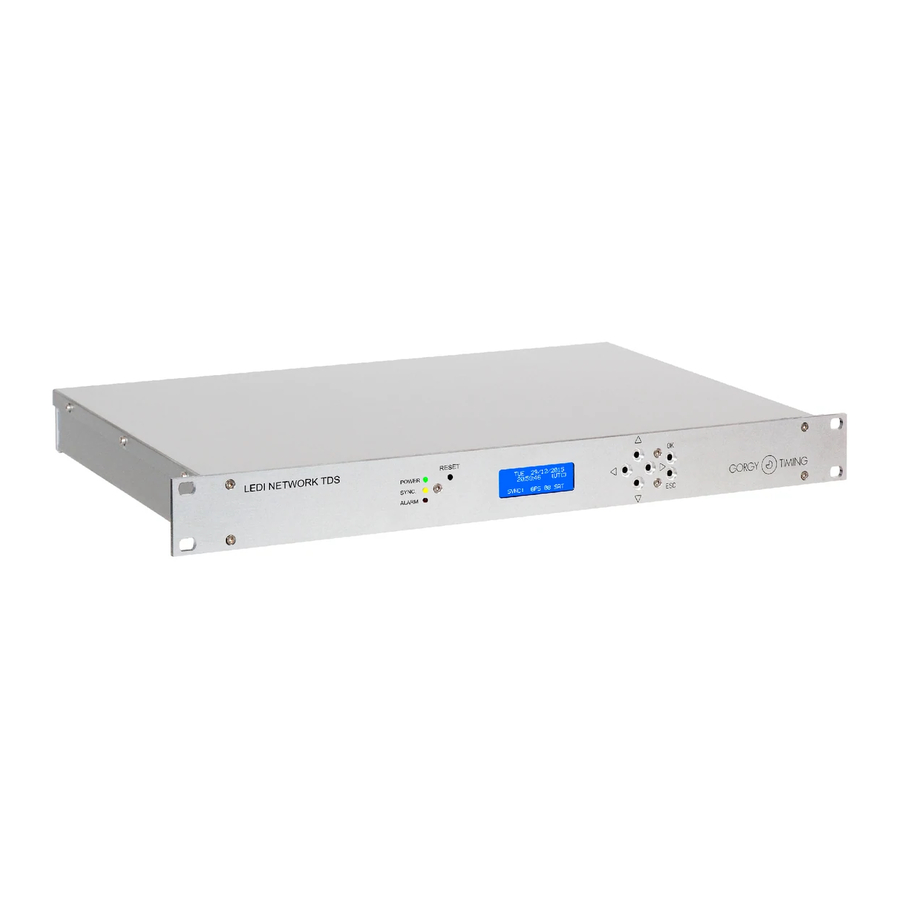
2. QUICKSTART CONTENT OF THE PACKAGE Upon delivery, the box should contain the following elements: ► The 19" rack, bearing the mention ”LEDI NETWORK TDS” ® ► A C13 power supply cable without locking ► An RJ45 Network cable ► A DVD-ROM that contains software and documentation ☛... -
Page 8: Setting Up The Server, General Information
3. SETTING UP THE SERVER, GENERAL INFORMATION 3.1. MANUAL NETWORK CONFIGURATION By default, the server obtains its IPv4 and IPv6 addresses from a DHCP server. There are several ways to manually modify IPv4 and IPv6: ► By accessing the web interface, in the « Network » page. (See section 5.2.3. “Page Network") ►... -
Page 9: Ntp Protocol General Information
3.4. NTP PROTOCOL GENERAL INFORMATION NTP (Network Time Protocol) is a network protocol designed to synchronize a device (the client) with a time reference (the server). The LEDI NETWORK TDS V1 is a server that ® can synchronize numerous client devices from a main time source and optionally a client capable of synchronizing on several servers. -
Page 10: General Facts About Synchronization
3.5. GENERAL FACTS ABOUT SYNCHRONIZATION The synchronization is the process during which, a local clock (internal) will be tuned by aligning on a distant clock (the reference). A local clock works with a reference frequency signal generated by an oscillator. The LEDI ®... -
Page 11: Front Lcd Display
4.1. STARTUP During start-up, the LCD screen displays the message “Init…” until the embedded software starts and displays the loading advancement of the various software modules: Init . . . LEDI NETWORK TDS V1 v18.106 *- *********** *-USER INTERFACES -* The firmware version is displayed on the second line during the loading process. -
Page 12: Time Display
4.2. TIME DISPLAY Normal operating: ► Time and date are displayed continuously. ► The last line displays the current synchronization source. Here are the various possible messages: ► NTP synchronization input 20/07/2018 20:59:46 (LOC) SYNC: EXT NTP SRV ► DCF or GPS synchronization input. 20/07/2018 •... -
Page 13: Alarm Conditions
“Output” tab. This can happen on occasions during initializing and in normal opera- ting. If the problem persists and the corresponding outputs no longer broadcast time codes, please contact Gorgy Timing Customers’ Service. ► SERVER LOCKED: The time outputs have been deactivated by a user. -
Page 14: Manual Ipv4 / Ipv6 Settings
4.4. MANUAL IPV4 / IPV6 SETTINGS Use the blue LCD screen and the buttons to manually set up the IP configuration of the LEDI NETWORK TDS V1. ® 4.4.1. Display current IP addresses ► Press any arrow key to display as screen showing the current IP addresses for se- veral seconds. -
Page 15: Ipv4
4.4.3. IPv4 The following diagram describes the IPv4 configuration menus tree. An explanatory paragraph is provided below the diagram: Manual Mode Automatic mode CONFIGURE IP ADDRESS CONFIGURE IP ADDRESS Keys Step 1 « ↑ » and « ↓ » Static DHCP Button "OK"... - Page 16 ► Step 2 ► Static mode: The menu allows to set up: - The IPv4 address (IP line) - The sub-mask (MASK line) - The network gate (GATE line) The line being modified blinks on the screen. Use the direction keys “↓” and “↑” to adjust the field value. Use the direction keys “”...
-
Page 17: Ipv6
4.4.4. IPv6 The following diagram describes the IPv4 configuration menus tree. An explanatory para- graph is provided below the diagram: Manual Mode Automatic mode Use DHCP with IPv6 ? Use DHCP with IPv6 ? Keys Step 1 « ↑ » and « ↓ » Button "OK"... - Page 18 ► Step 1 Use the direction keys “↓” and “↑” to switch between Static and DHPCv6 mode. Use the “ESC” key to return to the previous menu. Use the “OK” key to validate the selection and move on to step 2. ►...
-
Page 19: Restart Unit
4.5. RESTART UNIT ► Choose this option to reboot the LEDI NETWORK TDS V1. ® MAIN MENU ‹ RESTART ‹ › UNIT › MDE-LEDI-NETWORK-TDS-4099V1.0... -
Page 20: Web Interface
5. WEB INTERFACE 5.1. PRESENTATION The LEDI Network TDS V1 can be configured and supervised through a WEB interface. ® This interface provides you with the following features: ► Management of network parameters ► Management of SNMP parameters ► Management and diagnostic of server software itself ►... - Page 21 On the left, a menu allows switching between the different pages of the web interface. 1. Index: general information about the product. 2. Network: Settings of network parameters. 3. Alarms: Configuration of the static relays. 4. SNMP: Configuration of the SNMP module. 5.
- Page 22 ► One or several of the following buttons can be found on each Web page: Saves the changes in flash memory instead of temporary memory. Therefore the information is saved even in case of « Save Settings » button power interruption. Some parameters require the device to be restarted in order to be applicable.
-
Page 23: Index" Page
NETWORK TDS V1 ® ► Serial number ► Displays the GORGY TIMING serial number of the product. This is a 6 digits number which is the same than the one stamped on the bottom or back- ground of the rack. - Page 24 System ► MAC Address ► The Medium Access address of the Ethernet interface of the device. ► Firmware version ► The current version of the embedded software. The first two digits correspond to the year, the other three digits correspond to the day of the release date of the firmware.
-
Page 25: Network" Page
5.2.3. "Network" page MDE-LEDI-NETWORK-TDS-4099V1.0... - Page 26 IPv4 Settings The current IPv4 parameters are displayed. ► Address from DHCP server If the box is checked, the LEDI NETWORK TDS V1 attempts to get an IPv4 ad- ® dress from a DHCP server on startup. Failing to obtain an address this way will result in the server using its automatically configured IPv4 address.
-
Page 27: Alarms" Page
Unchecking the previous box gives access to the following settings: ► IP Address Sets up the IPv6 address of the LEDI Network TDS V1 on the network either ® in a reduced format (i.e. fc00::0001 in the example above) or in a complete format (i.e. - Page 28 E-Mail alerts Management ► Use this page to set up the parameters for sending email as well as sending conditions. ► The “SMTP Server Address” field can be filled with an IP address or a host name. ► The SMTP server in use must be set up as to accept SSL unsecured connections. ►...
-
Page 29: Snmp" Page
5.2.5. "SNMP" page Use this section to set up the supervision SNMP agent running on the LEDI NETWORK ® TDS V1. System information ► The three fields “Name”, “Location” and “Contact” can be freely filled to provide information about the LEDI NETWORK TDS V1 ®... - Page 30 Traps ► SNMP traps are alarm messages sent by the LEDI NETWORK TDS V1 in different ® situations. ► Please refer to the MIB for more information about the SNMP traps messages of the LEDI NETWORK TDS V1. ® ► Up to 8 IPv4 addresses can be configured on different slots with different SNMP versions.
-
Page 31: Ntp" Page
5.2.6. "NTP" page The NTP configuration panel indicates the synchronization mode used by the server or selected by the NTP software, as well as the servers defined by the user. NTP Server section Use this part to setup parameters for the NTP server Enable NTP Server ►... - Page 32 Authentication policy ► Use this field to choose whether the server will answer to a NTP request, based on presence of a security MD5 hash. The server can be configured to accept any request, only secured requests or only unsecured requests. Serve symmetric active/passive requests ►...
- Page 33 Use MD5 encryption ► Activates the MD5 hash on NTP broadcast messages. ► Select the key in the menu (“Key #1” to “Key #8”) and fill in the corresponding field in the “MD5 Keys” area to activate MD5 hashes. When the autonomy is depleted ►...
- Page 34 Polling rate ► This list defines how often the NTP servers will be polled for synchronization. Number of requests ► This list configures the number of NTP messages to be sent in a train of requests at the requested polling rate. Client mode ►...
- Page 35 Server list Use these fields to enter NTP servers IPv4 addresses manually. The “Use gateway” box must be checked if the contacted server is outside the local network. If the index of an MD5 key is provided, the LEDI NETWORK TDS V1 adds corres- ®...
-
Page 36: Input" Page
5.2.7. "Input" page The input page regroups information and settings about the time input available on the LEDI NETWORK TDS V1. ® Time Base State ► This field provides information about the type of oscillator of the time base. Current Frequency Source ►... - Page 37 Enable autonomous mode ► Checking this box will cause the LEDI NETWORK TDS V1 to ® switch to ‘Free Running” mode where it will run autonomously wi- thout a synchronization source. When the box is checked, the fol- lowing options become available: ►...
- Page 38 NTP client input version Description and available parameters ► The table below details the available features for each synchronization input type DCF/GPS Type Series of fixed characters including the synchronization type (DCF or NTP). Offset to Reports the difference between the internal clock Not available internal time and the NTP server...
- Page 39 Options Maximum autonomy when synchronization is lost ► When the time source is lost, the device works in autonomous mode. When the auto- nomy time end is reached, the device’s outputs and NTP server stop providing time. The autonomous running duration can be set or deactivated here (void or “disabled” setting).
-
Page 40: Output" Page
5.2.8. "Output" page Use this page to find information about the status and configuration options of all the output cards in the LEDI NETWORK TDS V1 and set them up one by one. ® The extension cards appear in a table at the top of the page. ►... - Page 41 In case of no internal communication with the output cards, the front screen displays the message “Output Alarm!”. If the issue persists over time or after rebooting the device, please contact Gorgy Timing Customers’ Service Options standard communes The image below shows the information field shared by all configuration cards. The confi- guration page of the cards displays all or part of these fields.
- Page 42 Disable the output card ► Disabling the output cards will have the following effects: Card Effects IRIG The 1kHz carrier is present but no longer modulated POLAR PULSE Polarized impulsion generation is stopped UTC (Fuseau horaire) ► Under normal operating conditions, the internal time of the device is UTC time. In order to send local time to the outputs, it is necessary to apply a shift from the UTC time first.
- Page 43 Specific options Some output cards have specific setup options. AFNOR/IRIG-B : ► The IRIG frame format can be modified. POLAR PULSE : ► Alarm: alarm indicator (power, open serial circuit, parallel short-circuit). ► Output time: displaying the time sent to impulsion clocks. ►...
- Page 44 Starting procedure: ► Tick the box “Disable the output card” and press “Save Settings” to stop the impulsion generation. ► Connect the clock line to the back slot. ► Set up the offset and the DST policy. ► Set up the period, the impulsion time and the format. ►...
-
Page 45: Interface Page
5.2.9. INTERFACE page Use this page to set up the different management interfaces of the LEDI NETWORK TDS V1. ® A. User Accounts Disable root account ► By default, the LEDI Network TDS V1 can be accessed via a root account. This ®... -
Page 46: Front Lcd
B. Front LCD Local time on front LCD Checking this box displays the local time on the LCD front screen with the mention “(LOC)”. Otherwise, UTC time is displayed with the mention “(UTC)”. Check the time zone and DST boxes to configure them. Custom LCD message ►... - Page 47 7. Enter the command put ssl.cert 8. Enter the command put ssl.key 9. Enter the command quit The picture below shows the mes- sages displayed. Here, the certifi- cate files are in C:\Users\xgerault\ Certificats and the IP address of the module is 192.168.0.128. Enable Telnet console et Enable SSH console ►...
- Page 48 SSH client memorize it or not. ► Under Windows Windows provides the application telnet.exe. To connect to a Gorgy Timing product: 1. Launch “cmd.exe“ 2. Enter “telnet <IP> 9999” where <IP> is the IP address.
- Page 49 FTP. To get the latest version of the NTPServ firmware, please contact Gorgy Timing Customer’s Service. Enable ENDMI Protocol ► If enabled, the Gorgy Timing discovery protocol will be activated on the LEDI ® NETWORK TDS V1. The device will therefore be detectable by GTNetworkManager2. Enable the front panel menu ►...
-
Page 50: Restart Button
D. Restart button The device can be remotely rebooted using the Restart button at the bottom of the page. Then, the web page will not be accessible for approximately 1 min. until the unit restarts. 5.2.10. UPDATE page ☛ WARNING: Depending on the update, the product may reset all settings to factory default after updating the firmware. - Page 51 The picture below shows an example of the observed command lines. Here, the firmware is on the Desktop (C:\Users\jappaix\Desktop) and the module IP address is 192.168.0.22. 5 - Wait for the module to reboot, do not turn it off before rebooting is complete. 6 - In the terminal, use the “cd”...
- Page 52 ► Updating via the SSH interface For this procedure, the SSH interface must be activated in the device’s settings. 1- Open a terminal (Start menu -> Execute ->"cmd") 2- Type "pscp <firmware paht> root@<module IP address>:/", ENTER If pscp is unavailable, please install the Putty package from the https://www.chiark.greenend.org.uk/~sgtatham/putty/latest.html web page then restart step 2 Password: "gtmt"...
-
Page 53: Diagnostics" Page
5.2.11. “Diagnostics” page The Diagnostics Web page can be access via the address <IP>/html/_diag.html. It contains diagnostics information and allows launching tests on the network module. NTP statistics ► NTP Requests received indicates the number of queries received by the network module since startup.. - Page 54 ► Uptime is the functioning duration of the server at the time of the leap. NTP Configuration watcher That part is exclusively used by Gorgy Timing. It is not finalized in the provided software. SCP Time Logging ► Enable SCP Logging activates the detailed log of the NTP answers by the client on a SD card.
-
Page 55: Appendixa - Connections
6. APPENDIX A – CONNECTIONS This section contains a description of every possible connection on the LEDI NETWORK ® TDS V1. All the connections are made at the back of the device. FUSES Management DCF/GPS and NTP T-2A Sync. Ant 230VAC RESET OUTPUT CARDS... -
Page 56: Dcf-Gps Antenna
6.1. DCF-GPS ANTENNA External dimensions of the rack: Height: 150mm – Width: 80mm – Depth: 50mm IP 54 ► Install away from interference sources such as neon lights, computer screens, etc.. 6.1.1. DCF Antenna Réf : 3D6 (four meters cable included) Receipt frequency: 77.5 kHz ►... - Page 57 ☛ Although it is not much perturbed by other systems, it is recommended to avoid installing the antenna directly below a radar. ► Install the antenna vertically. No specific orientation is required. ► The green indicator must be flashing every second to indicate reception of at least one satellite signal.
-
Page 58: Afnor-Nfs-87500 / Irig-B Output
6.2. AFNOR-NFS-87500 / IRIG-B OUTPUT Time code AFNOR-NFS-87500/IRIG-B is delivered through a 4 points coupler. An identical signal is available between the first terminal (on the left) and the second ter- minal. A second signal identical to the first is available between the third terminal and the fourth terminal (on the right). -
Page 59: Appendix Boutput Codes Format
7. APPENDIX OUTPUT CODES FORMAT 7.1. AFNOR/IRIG-B NFS87500 Frame format MDE-LEDI-NETWORK-TDS-4099V1.0... - Page 60 Bit encoding The signal is modulated only on 'B' card. The 'T' card output signal has TTL level (5V). MDE-LEDI-NETWORK-TDS-4099V1.0...
-
Page 61: Appendixc - Maintenance
8. APPENDIX C – MAINTENANCE 8.1. CARD REPLACEMENT + IMPULSION CARD POWER tools: ► Torx T15 screwdriver: front face (rack) or top plate (case) ► Torx T10 screwdriver: lid (rack) + front face (case) + output cards ► 5.5 wrench for M3 bolts: output cards + impulsion card power ►... -
Page 62: Microcontrolers Replacement
Torx T10 screwdriver: lid (rack) + front face (case) + output cards ► PLCC extractor: microcontroller ► ► Gorgy Timing reference: CIS8951RC2P ► Unplug every cable at the back of the product ► Remove the four M3.5 screws from the front face ►... -
Page 63: Output Cards Addresses Switches
8.3. OUTPUT CARDS ADDRESSES SWITCHES Each output card of the LEDI NETWORK TDS V1 has an address which must be unique. ® These addresses are determined by switches on each output card. When replacing/adding a new card, the user must make sure that the cards addresses are unique. Below is a recapitulative table of the addresses depending on the switches positions: Output 1 (closest from... -
Page 64: Top & Irig B Dcls Time Code Output
8.4. TOP & IRIG B DCLS TIME CODE OUTPUT TOP and IRIG DCLS outputs cards can provide several signal formats: ► ► Differential TTL (RS422) ► Phototransistors or static relays, depending on the card type. Sortie 4 Output 4 Sortie 3 Output 3 For each output Signal format... -
Page 65: Supervision Protocols
8.5. SUPERVISION PROTOCOLS 8.5.1. Syslog messages catalog The table below depicts Syslog messages sent by the device. Syslog Syslog category Message category Sent text sererity (value) (value) user (1) Configuration via la face avant A new configuration has been defined through the front LCD & buttons info (6) user (1) Configuration via Telnet... -
Page 66: Appendixd - Fixes
9. APPENDIX D – FIXES This section provides answers to the frequently asked questions about the use of your NTP device. Before starting, please make sure that the GTNetworkManager2 is installed on your computer. I MADE A SCAN WITH GTNETWORKMANAGER2, BUT I DON’T SEE ANY DEVICE! ►... - Page 67 THE CONFIGURATION WEB PAGE DOES NOT SHOW ANY OUTPUT? ► Press “F5” to refresh the web page then return to the output panel. If the output still does not appear, skip to the next step. ► Open a TELNET session: Telnet <...
- Page 68 +33 476 30 48 20 support@gorgy-timing.fr RADIO TIMING®, LEDI®, LEDICA®, HANDI® are trademarks by GORGY TIMING. Number of statement for training provider activity : 82 38 04877 38 Gorgy Timing RC74B38 - Any technical, aesthetic, color modifications can be made without notice. MDE-LEDI-NETWORK-TDS-4099V1.0...
Need help?
Do you have a question about the LEDI NETWORK TDS V1 and is the answer not in the manual?
Questions and answers