Table of Contents
Advertisement
Quick Links
Advertisement
Table of Contents

Related Manuals for Holtek Gang-Writer8-8


Summary of Contents for Holtek Gang-Writer8-8
- Page 1 Gang-Writer8-8 User’s Guide Revision: V1.00 Date: December 13, 2018...
-
Page 2: Table Of Contents
Gang-Writer8-8 User’s Guide Table of Contents 1 Overview ......................3 1.1 Gang-Writer8-8 ........................3 1.2 Main Features ........................3 1.3 Hardware Introduction ......................3 1.4 Software Introduction ......................4 2 Programming Module Independent Operation ..........5 2.1 Online Programming Mode ....................5 2.2 Offline Programming Mode ....................6 3 Using the Programming Module together with the Base Board .... -
Page 3: Overview
4 programming units, namely ICP1~ICP4. This is used together with the G-ICPB00040 which is the Base Board. Together they can implement a powerful means of programming 8 Holtek 8-bit Flash MCUs in parallel to meet the high efficiency requirements for volume production. -
Page 4: Software Introduction
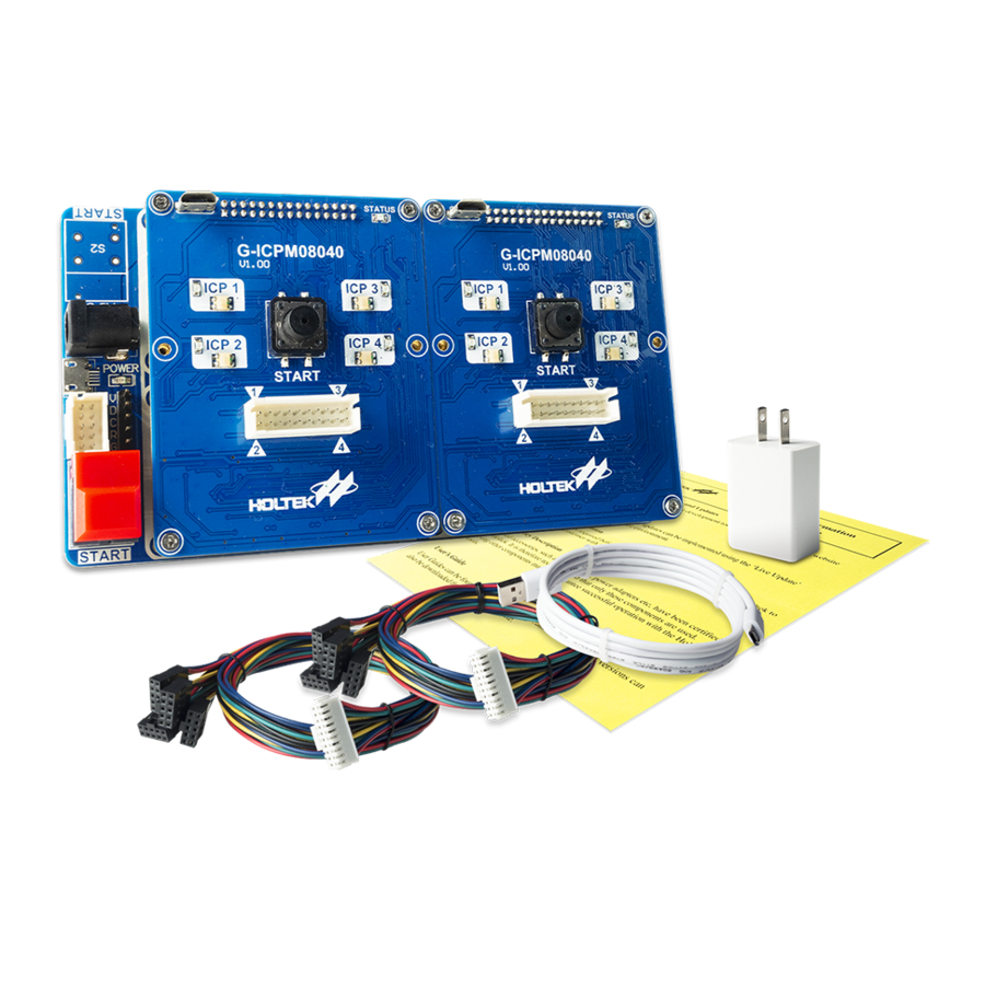
Gang-Writer8-8 User’s Guide Micro USB Interface STATUS Indicator ICP1-RUN ICP1-OK/FAIL START Key 20PIN (5PIN×4ICP) PHB Connector Figure 2. G-ICPM08040 – Programming Module Programming Module Slot DC/USB Power Interface START Key Figure 3. G-ICPB00040 – Base Board 1.4 Software Introduction The software HOPE3000 (V3.26 and above) is used, refer to appendix HoltekEWriterUsersGuide(125).pdf for detailed HOPE3000 usage description. -
Page 5: Programming Module Independent Operation
Gang-Writer8-8 User’s Guide Figure 4. HOPE3000 Interface 2 Programming Module Independent Operation 2.1 Online Programming Mode In this mode, only the ICP1 unit works. Connect the programming module to a PC using a USB cable and open the software. The ICP1-RUN LED will be illuminated indicating that it is in the online programming mode, as shown in Figure 5. -
Page 6: Offline Programming Mode
Gang-Writer8-8 User’s Guide 2.2 Offline Programming Mode Offline Programming Data Download Connect the programming module to a PC via a USB cable. After the module has successfully connected, open the desired file and download it, as shown in Figure 6. Refer to appendix HoltekEWriterUsersGuide(125).pdf for the specific software operation procedures. -
Page 7: Using The Programming Module Together With The Base Board
Gang-Writer8-8 User’s Guide Programming Mode Selection Either 2 or 4 site parallel programming can be selected using the OPTION S/W settings according to the actual requirements, as shown in Figure 8 and Table 1. With regard to 6 or 8 site parallel programming description, refer to 3.2 Programming Mode Selection. - Page 8 Gang-Writer8-8 User’s Guide Figure 9. Offline Programming Data Download – Module & Base Board Offline Programming After the offline programming data has been downloaded successfully, remove the USB cable from the PC. Connect a 5V/3A power to the programming module after which then the STATUS indicator of each programming module will be on.
-
Page 9: Programming Mode Selection
Figure 11. Programming Mode Selection – Standard Mode Extension Mode In the offline programming mode, if the base board works together with 4 programming modules, up to 16 Holtek 8-bit Flash MCUs can be programmed in parallel as shown in Figure 12. Rev. 1.00 December 13, 2018... - Page 10 Gang-Writer8-8 User’s Guide Figure 12. Programming Mode Selection – Extension Mode Rev. 1.00 December 13, 2018...
-
Page 11: Considerations
Gang-Writer8-8 User’s Guide 4 Considerations • Regarding the power supply (5V/3A) and the programming lines, it is strongly recommended to use the original accessories included in the product. • Each separate programming channel (ICPx) provides a current of only 150mA. -
Page 12: Appendix A Led Status Description
Gang-Writer8-8 User’s Guide Appendix A LED Status Description Programming Programming Complete LED Indicator Power On Status Process Status Status Online Programming First on then off. Offline programming data download has completed and the ICP1 connection is successful. STATUS Flash (Mode2) then off. -
Page 13: Appendix B 20Pin (5Pin×4Icp) Phb Connector
Gang-Writer8-8 User’s Guide LED Flash Status Definition Mode1: …… Mode2: …… Mode3: …… Mode4: …… Figure 14. LED Flash Status Definition Appendix B 20PIN (5PIN×4ICP) PHB Connector Figure 14. 20PIN (5PIN×4ICP) PHB Connector Table 3. 20PIN (5PIN×4ICP) PHB Connector Rev. 1.00... -
Page 14: Appendix C G-Icpb00040 (Base Board) External Key
Gang-Writer8-8 User’s Guide Appendix C G-ICPB00040 (Base Board) External Key Figure 15. J2 Explanatory Chart PIN2: The external key can enable the SLOT1~SLOT4 programming at PIN1: GND the same time. PIN4: The external key can enable the SLOT1 and SLOT3 programming PIN3: GND at the same time. - Page 15 However, Holtek assumes no responsibility arising from the use of the specifications described. The applications mentioned herein are used solely for the purpose of illustration and Holtek makes no warranty or representation that such applications will be suitable without further modification, nor recommends the use of its products for application that may present a risk to human life due to malfunction or otherwise.
Need help?
Do you have a question about the Gang-Writer8-8 and is the answer not in the manual?
Questions and answers