Table of Contents
Advertisement
Quick Links
Advertisement
Table of Contents

Subscribe to Our Youtube Channel
Related Manuals for Advantage Controls SFS Series

Summary of Contents for Advantage Controls SFS Series
- Page 1 Manual SFS Series Solid Feed Systems Installation Maintenance Repair Manual Advantage Controls 4700 Harold Abitz Dr. Muskogee, OK 74403 Phone: 918-686-6211 Fax: 888-686-6212 www.advantagecontrols.com email: support@advantagecontrols.com 05/2020...
-
Page 2: Table Of Contents
SFS Series Manual Table of Contents Contents Page Introduction ................3 Model Numbering ...............3 Options ..................4 Installation ..................5 Electric Models ..............5 Non-Electric Models ............6 III. Operation ...................6 Option C-2 Operation ..............7 Front Panel Display ............7 a. System Menu Functions ..........7 b. Control Panel LED Lights ...........7 c. -
Page 3: Introduction
Introduction The SFS system is engineered to inject city water into a bowl containing a solid chemical which will then be dissolved and drained into a chemical solution tank based on high/low level switches. All systems primarily consists of: Liquid Level controller (except SFS-G01, SFS-G02, SFS-10 and SFS-20 models). A Universal dissolving bowl. -
Page 4: Options
Gray dissolving tank Provide 120 volt level controller for remote mounting with SFS-101 Non Advantage Controls metering pump mounting adapter Remove pressure regulator from 205, 305 & 405 (R2, R3 to remove more than one) Dual timer on SFS-205 instead of level controller (Includes MicroTron Timer manual) -
Page 5: Installation
Installation Non-Electric Model Installation Figure A Step 1 • Remove the two screws on top plate of solid feeder (Fig. A). Figure B • Lift off cover and set on it’s side. Step 2 • Clip weighted float to bottom of wire hanger via cutout (Fig. B). Step 3 • Insert weighted float back into solid feeder (Fig. C). Note: Make sure weighted float is centered on wire hanger and that the hanger moves freely up... -
Page 6: Electric Models
Electric Models The standard units are designed to be free standing or wall mounted. The level controller, control solenoid valve and level float assembly are all prewired for easy installation. Models with 120 VAC controllers are supplied with an 8 foot, 3-wire grounded power cord. Models with 12 VDC controllers are supplied with a wall plug-in transformer. A ¼”... -
Page 7: Option C-2 Operation
Option C-2 Operation Front Panel Display System Menu Functions: Calibrate - Conductivity of dissolved liquids. Switch At - Conductivity value in which the system will advance to the next bowl. Spraying on #1 - Identifies the bowl in use. Zero Cond - Identifies the zero conductivity value. Run Mode Explanation: Power- Illuminates when the controller is supplied with 120/240VAC. Relay - Illuminates when a relay is activated. -
Page 8: Resetting Bowls
Resetting Bowls When AUTO RESET is enabled, this will allow the controller to automatically reset itself to the first bowl after the last bowl has gone “low conductivity”. Set to Y will enable. When disabled (Set to N), the controller will function as below: When the controller is utilizing Bowl #2, it must be manually switched back to Bowl #1, presummably after the solid chemical jugs have been changed. -
Page 9: Diagrams
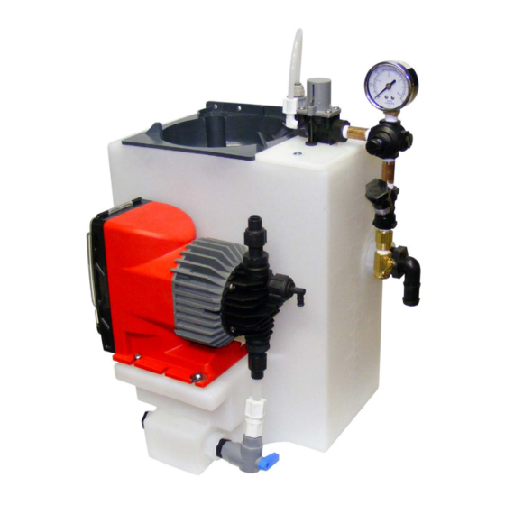
Diagrams SFS-101 Parts List SFS-101 1. SFS-DB-1 Dissolving bowl (includes spray arm) 2. SFS-TANK-101 Replacement Tank 3. 2C4A000056 1” MNPT to 3/4” tubing barb overflow elbow 4. SFS-SUCTION Outlet pump suction assembly 5. SFS-SB-12V Brass solenoid valve with y-strainer 12 volt D.C. 6. -
Page 10: Sfs-G01
SFS-G01 Parts List SFS-G01 1. SFS-DB-1 Dissolving bowl (includes spray arm) 2. SFS-TANK-G01 Replacement Tank 3. SFS-SUCTION Outlet pump suction assembly 4. 2C4A000056 1” MNPT to 3/4” tubing barb overflow elbow 5. SFS-BV Brass inlet valve 6. SFS-Y Y-strainer 7. SFS-PR Pressure regulator 8. -
Page 11: Sfs-G02
SFS-G02 Parts List SFS-G02 SFS-BV Brass inlet valve SFS-TANK-G02 Tank SFS-DB-1 Dissolving bowl 2C4A000056 1” MNPT to 3/4” tubing barb overflow elbow SFS-SUCTION Outlet pump suction assembly SFS-LF-G02 Level float & inlet valve assembly (includes weight & polyboard) SFS-PR Pressure regulator SFS-Y Y-strainer SFS-PG... -
Page 12: Sfs-105
SFS-105 Parts List SFS-105 1. SFS-DB-1 Dissolving bowl (includes spray arm) 2. SFS-TANK-101 Replacement Tank 3. 2C4A000056 1” MNPT to 3/4” tubing barb overflow elbow 4. SFS-SUCTION Outlet pump suction assembly (left or right) 5. SFS-SB-120V Brass solenoid valve with y-strainer 120 volt A.C. 6. -
Page 13: Trouble Shooting Guide
VI. Trouble Shooting PROBLEM CAUSE REMEDY Solenoids not Power Source Check power source activating Output Power Check or replace fuse Bad or Dirty Level Floats Clean or replace as needed Faulty Wiring to Level Floats Level floats as needed System not spraying Dirty Bowl Injection Nozzle Clean as needed Clogged Y-Strainer Screen Clean as needed... -
Page 14: Warranty And Factory Service Policies
VII. Manufacturer’s Product Warranty Advantage Controls warrants control systems of its manufacture to be free of defects in material or workman- ship. Liability under this policy extends for 24 months from date of installation (sensors are not included). Liability is limited to repair or replacement of any failed equipment or part proven defective in material or workmanship upon manufacturer’s examination. - Page 15 - Notes -...
- Page 16 Get the Advantage in Water Treatment Equipment Advantage Controls can give you the Advantage in products, knowledge and support on all of your water treatment equipment needs. Cooling Tower Controllers Boiler Blow Down Controllers SET UP ENTER HOME Blow Down Valve Packages...
Need help?
Do you have a question about the SFS Series and is the answer not in the manual?
Questions and answers