
Related Manuals for ITRON Routing Node ERT

Summary of Contents for ITRON Routing Node ERT
- Page 1 Routing Node ERT® Gateway Mesh Installation Guide INSTALLATION GUIDE knowledge to shape your future 815-0322-00 Rev0 Itron, Inc. Page 1 of 30 15 June 2020...
- Page 2 All other product names and logos in this documentation are used for identification purposes only and may be trademarks or registered trademarks of their respective companies. For more information about Itron or Itron products, go to www.itron.com. If you have questions or comments about a software or hardware product, contact Itron Technical Support Services. Contact Email: support@itron.com...
-
Page 3: Table Of Contents
Routing Node ERT® Gateway Mesh Installation Guide Contents Ro u t i n g No d e ERT ®Ga t e wa y Me s h I n s t a l l a t i o n Gu i d e... - Page 4 Routing Node ERT® Gateway Mesh Installation Guide Mounting the ERT Gateway on a Davit Arm Connecting the Ground Wire (If Required) Connecting the ERT Gateway Power Connecting the Power Cable ERT Gateway Wiring Diagram Appendix: ERT Gateway Specifications Dimensions and Weight...
-
Page 5: Important Safety And Compliance Information
Connect the equipment into an outlet on a circuit different from that to which the receiver is connected. ■ Consult the dealer or an experienced radio or TV technician for help. 15 June 2020 815-0322-00 Rev0 Itron, Inc. Page 5 of 30... -
Page 6: Canada, Ised Compliance
Routing Node ERT® Gateway Mesh Installation Guide 1 Important Safety and Compliance Information Canada, ISED Compliance Compliance Statement Canada This device complies with Innovation, Science and Economic Development Canada (ISED) license-exempt RSS standard(s). Operation is subject to the following two conditions: (1) this device may not cause interference, (2) this device must accept any interference, including interference that may cause undesired operation of the device. -
Page 7: Modifications And Repairs
Caution: To ensure FCC and ISED compliance, and system performance, this device and antennas shall not be changed or modified without the express approval of Itron. Any unauthorized modifications or operation beyond or in conflict with these instructions for use could void the user's authority to operate the equipment. -
Page 8: Getting Started: Routing Node-Ert Gateway Mesh
G etting Started: Routing Node-ERT Gateway Mesh The Routing Node-ERT Gateway Mesh provides a unified means of reading Itron R300/R400 electric meters over an IPv6 network. The ERT Gateway Mesh communicates directly with the Connected Grid Router (CGR). The gateway utilizes RF links with optimized modulation rates. The CGR then transmits the data to the OpenWay Operations Center (a part of the head-end system) over the utility's backhaul communication solution. -
Page 9: Ert Gateway Mesh Related Documents
Other vertical structures Note: To achieve optimal RF performance the ERT Gateway Mesh should be mounted at the height recommended by Itron’s Global Network Design Center (GNDC). Integrated mounting and coupling brackets secure the device in high winds and under heavy ice loads. -
Page 10: Ert Gateway Mesh Components
Warning! In accordance with FCC rules, unapproved modifications or operation beyond or in conflict with these use instructions could void the user's authority to operate the equipment. Only authorized Itron personnel may open the ERT Gateway. Unauthorized access or modifications to the ERT Gateway will void the warranty. -
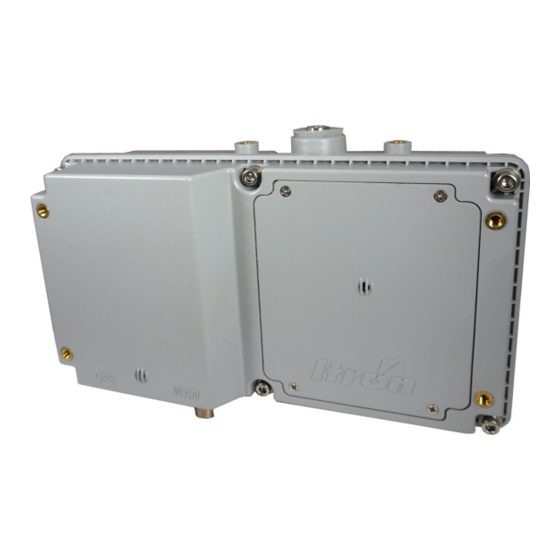
Page 11: Ert Gateway Mesh Housing
The radio antennas are included with the gateway and are directly mounted to the housing. Caution: Only authorized Itron personnel may open this device. Unauthorized access or modifications to this product voids the warranty. Per FCC rules, unapproved modifications or operation beyond or in conflict with the installation instructions in this guide could void the user's authority to operate the equipment. - Page 12 Routing Node ERT® Gateway Mesh Installation Guide 2 Getting Started: Routing Node-ERT Gateway Mesh type N female. Ground lug The ground lug is optional on the ERT Gateway and is provided for utilities that require a separate earth ground. Note: When the ERT...
-
Page 13: Ert Gateway Antennas
(e.i.r.p.) is not more than that permitted for successful communication. Antennas not included in this list and approved by Itron are strictly prohibited for use with this device. Installing the Routing Node ERT Gateway with an unapproved antenna will void the product warranty and can void the user's authority to operate this equipment. -
Page 14: Planning An Ert Gateway Installation
On a structure or in a location that can physically support the weight of the ERT Gateway (and its mounting hardware). Caution: Always get permission to install the ERT Gateway at the selected site prior to installation. If you have questions or need help, contact Itron Support. 15 June 2020 815-0322-00 Rev0... -
Page 15: Installation Location Information
Unauthorized access or modifications to the ERT Gateway will void the warranty. Propagation Study for the ERT Gateway Installation Site Prior to the ERT Gateway field installation, contact Itron. Itron performs a propagation study to: ■ evaluate the quantity and types of network endpoints. -
Page 16: Ac Power Requirements
Caution: Each installation is unique. You must ensure the mounting hardware securely supports the ERT Gateway. The ERT Gateway without the mounting hardware weighs 8 pounds. Itron recommends you consult a qualified engineer to verify load requirements and safety issues. Installers must comply with local codes when the ERT Gateway is installed. -
Page 17: Installing The Ert Gateway
I nstalling the ERT Gateway This chapter provides the Itron-approved instructions to install an ERT Gateway in the field. The ERT Gateway can be installed in a variety of locations. This installation profile uses AC mains power. Note: Before the ERT Gateway installation, ensure that the selected location will support the weight of the gateway and its mounting hardware. -
Page 18: Installing The Battery
Routing Node ERT® Gateway Mesh Installation Guide 4 Installing the ERT Gateway Installing the Battery 1. Remove the battery cover by loosening the four screws securing it. These are captive screws and do not need to be fully removed from the battery cover. -
Page 19: Attaching The Ert Antenna
Routing Node ERT® Gateway Mesh Installation Guide 4 Installing the ERT Gateway Attaching the ERT Antenna Warning! Install only the provided ERT antenna. 1. Remove the antenna from the shipping package. 2. Verify that the foam seal is seated in the N-connector cavity on the top of the ERT Gateway. -
Page 20: Attaching The Wan Antenna
Routing Node ERT® Gateway Mesh Installation Guide 4 Installing the ERT Gateway Attaching the WAN Antenna Warning! Install only the provided WAN antenna. 1. Remove the WAN antenna from the shipping box. 2. Thread the WAN antenna onto the N-connector (labeled WAN) on the bottom of the ERT Gateway. -
Page 21: Mounting Hardware
Routing Node ERT® Gateway Mesh Installation Guide 4 Installing the ERT Gateway Mounting Hardware The mounting hardware for the ERT Gateway can be adapted to mount the gateway in many different locations. For pole or pipe mount profiles, the required mounting hardware includes: ■... - Page 22 Routing Node ERT® Gateway Mesh Installation Guide 4 Installing the ERT Gateway Table 1 Mounting Hardware (continued) Mounting brackets Brackets for wall mounting Brackets for pipe or pole mounting (bracket dimensions are shown) Mounting bolts Miscellaneous Mounting nuts, bolts, washers, split washers, and...
-
Page 23: Mounting The Ert Gateway On A Pipe
Routing Node ERT® Gateway Mesh Installation Guide 4 Installing the ERT Gateway Mounting the ERT Gateway on a Pipe In these instructions, the mounting plate is attached to the vertical pipe with the mounting brackets. The ERT Gateway housing is secured to the mounting plate. -
Page 24: Mounting The Ert Gateway On A Pole
Routing Node ERT® Gateway Mesh Installation Guide 4 Installing the ERT Gateway Mounting the ERT Gateway on a Pole 1. Follow the pipe mounting procedure for securing the mounting plate to the ERT Gateway (see Mounting the ERT Gateway on a Pipe). - Page 25 Routing Node ERT® Gateway Mesh Installation Guide 4 Installing the ERT Gateway arm without a street light, the power cable must be connected according to the local electrical codes. Important! If a photocell adapter cable supplies power to the ERT Gateway, the gateway must be grounded through the grounding lug on the bottom of the housing.
-
Page 26: Connecting The Ground Wire (If Required)
Routing Node ERT® Gateway Mesh Installation Guide 4 Installing the ERT Gateway Connecting the Ground Wire (If Required) Connect the cable ground wire to the grounding lug on the ERT Gateway. Note: Due to variable requirements for ground cable length, ground cables are not provided by Itron. -
Page 27: Ert Gateway Wiring Diagram
Routing Node ERT® Gateway Mesh Installation Guide 4 Installing the ERT Gateway 2. Secure the cable by tightening the retaining nut on the cable. ERT Gateway Wiring Diagram Power source and grounding connection are shown in the following illustration. Connection... -
Page 28: Appendix: Ert Gateway Specifications
A ppendix: ERT Gateway Specifications This section provides Routing Node ERT Gateway product specifications. Dimensions and Weight The ERT Gateway weight is listed in pounds. The dimensions are shown in inches. Component Weight ERT Gateway 8.0 lbs (with antennas) Pole mounting kit... -
Page 29: Antenna Specifications
The ERT Gateway is designed to operate with specific antennas. Antennas not expressly approved by Itron are strictly prohibited for use with the ERT Gateway and will be out of FCC and ISED compliance. Below are the two approved antennas. -
Page 30: Environmental Specifications
NEMA L5-15 (125V, 15A), NEMA L6-15 (250V, 15A) locking plug, or by directly splicing to the secondary power to meet electrical codes. Power wiring on the Itron- supplied power cable follows conventional color coding for AC wiring: green (ground), white (neutral), and black (hot).
Need help?
Do you have a question about the Routing Node ERT and is the answer not in the manual?
Questions and answers