
Related Manuals for York YHAU-CGN


Summary of Contents for York YHAU-CGN
- Page 1 MODEL YHAU-CGN/H 120-1600 TON 422-5626 KW Direct Fired Absorption Chiller-Heater Installation, Operation, Maintenance Form 155.32-ICOM2.EN.UL (1018) LD26829 Issue Date: October 1, 2018 New Release...
- Page 2 FORM 155.32-ICOM2.EN.UL ISSUE DATE:1/10/2018 IMPORTANT! READ BEFORE PROCEEDING! GENERAL SAFETY GUIDELINES This equipment is a relatively complicated apparatus. During rigging, installation, operation, maintenance, or service, individuals may be exposed to certain components or conditions including, but not limited to: heavy objects, refrigerants, materials under pressure, rotating components, and both high and low voltage.
- Page 3 FORM 155.32-ICOM2.EN.UL ISSUE DATE:1/10/2018 CHANGEABILITY OF THIS DOCUMENT In complying with Johnson Controls’ policy for continuous product improvement, the information contained in this document is subject to change without notice. Johnson Controls makes no commitment to update or provide current information automatically to the manual or product owner.
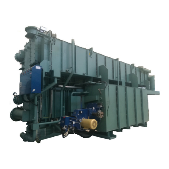
- Page 4 FORM 155.32-ICOM2.EN.UL ISSUE DATE:1/10/2018 LD22936a JOHNSON CONTROLS...
-
Page 5: Table Of Contents
FORM 155.32-ICOM2.EN.UL ISSUE DATE:1/10/2018 TABLE OF CONTENTS SECTION 1 - GENERAL CHILLER-HEATER INFORMATION AND SAFETY ..... . 11 Introduction ..............11 About this Manual . - Page 6 YHAU-CGN/H Control Center ........
- Page 7 FORM 155.32-ICOM2.EN.UL ISSUE DATE:1/10/2018 TABLE OF CONTENTS SECTION 7 – MAINTENANCE ............121 Exhaust Duct Inspection .
- Page 8 LIST OF FIGURES Figure 1 - YHAU-CGN/H-120-300EX(H/S) and 360EX - 1600EXW3(H/S)......16 Figure 2 - Two Step Direct Fired Absorption Chiller-Heater Cycle Diagram (Cooling Mode) .
- Page 9 Flow Diagram - Simultaneous Cooling and Residential Hot Water Only ....132 Figure 66 - YHAU-CGN/H Direct Fired Chiller-Heater with Evaporator Heating Flow Diagram - Simultaneous Heating and Residential Hot Water ..... 133 Figure 67 - YHAU-CH/AN/H Direct Fired Chiller-Heater with Additional Heat Exchanger Heating Flow Diagram - Cooling .
- Page 10 LIST OF TABLES FORM 155.32-ICOM2.EN.UL ISSUE DATE:1/10/2018 LIST OF TABLES Table 1 - Nozzle Arrangements 120-300EX(H/S) and 360EX(H/S)-1600EXW3(H/S) ..... 32 Table 2 - Nozzle Locations .
-
Page 11: Section 1 - General Chiller-Heater Information And Safety
SECTION 1 - GENERAL CHILLER-HEATER INFORMATION AND SAFETY INTRODUCTION YORK YHAU-CGN/H absorption chiller-heaters are manufactured to the highest design and construction standards to ensure high performance, reliability, and adaptability to all types of air conditioning installations. This chiller-heater is for air conditioning or cooling a manufacturing process. Use this... -
Page 12: Quality Assurance
SECTION 1 - GENERAL CHILLER-HEATER INFORMATION AND SAFETY FORM 155.32-ICOM2.EN.UL ISSUE DATE:1/10/2018 The unit warranty will be void if any modification to the unit is carried out without prior written approval from Johnson Controls. For warranty purposes, the following conditions must be satisfied: •... -
Page 13: Safety Labels
FORM 155.32-ICOM2.EN.UL SECTION 1 - GENERAL CHILLER-HEATER INFORMATION AND SAFETY ISSUE DATE:1/10/2018 SAFETY LABELS For safe operation, read the instructions first. Warning: This machine may start automatically without prior warning. Caution: Hot surface. Warning: Safety relief valve may discharge gas or liquid without prior warning. Warning: Risk of electric shock. - Page 14 FORM 155.32-ICOM2.EN.UL ISSUE DATE:1/10/2018 THIS PAGE INTENTIONALLY LEFT BLANK JOHNSON CONTROLS...
-
Page 15: Section 2 - Product Description
FORM 155.32-ICOM2.EN.UL SECTION 2 - PRODUCT DESCRIPTION ISSUE DATE:1/10/2018 SECTION 2 - PRODUCT DESCRIPTION The principle of refrigeration is the exchange of heat. In absorption liquid chilling, there are four basic heat exchange surfaces: the evaporator, the absorber, the generator, and the er. See Figure 1 on page Like any refrigeration system, absorption chilling uses evaporation and condensation to remove heat. -
Page 16: Figure 1 - Yhau-Cgn/H-120-300Ex(H/S) And 360Ex - 1600Exw3(H/S)
SECTION 2 - PRODUCT DESCRIPTION FORM 155.32-ICOM2.EN.UL ISSUE DATE:1/10/2018 Figure 1 - YHAU-CGN/H-120-300EX(H/S) and 360EX - 1600EXW3(H/S) ITEM COMPONENTS ITEM COMPONENTS JOHNSON CONTROLS... -
Page 17: How It Works (Direct Fired Units)
FORM 155.32-ICOM2.EN.UL SECTION 2 - PRODUCT DESCRIPTION ISSUE DATE:1/10/2018 HOW IT WORKS (DIRECT FIRED UNITS) The double effect (direct fired) absorption chiller-heater uses water as the refrigerant and LiBr as the absorbent. The vapor pressure of the LiBr solution is lower than the vapor pressure of the refrigerant. The vapor pressure of the LiBr solution is directly related to the amount of refrigerant (water) present in the solution with the LiBr salt and the solution temperature. -
Page 18: Absorber
The liquid is then pumped to the generators. The following section describes the unique 2-step evaporator-absorber design of the YHAU-CGN/H direct fired absorption chiller-heater. TWO-STEP EVAPORATOR – ABSORBER The evaporator, as well as the absorber, is split into two sections. This design, similar to a series-counter-flow chiller-heater arrangement along with the parallel flow cycle, enables lower LiBr solution concentrations. -
Page 19: Plate Type Heat Exchangers
FORM 155.32-ICOM2.EN.UL SECTION 2 - PRODUCT DESCRIPTION ISSUE DATE:1/10/2018 PLATE TYPE HEAT EXCHANGERS The dilute (weak) LiBr solution leaving the absorber section is pumped through various plate type heat exchangers (such as the low temperature heat exchanger, LTG refrigerant condensate heat exchanger, and high temperature heat exchanger) before it enters the high temperature generator and low temperature generator sections. -
Page 20: Condenser
SECTION 2 - PRODUCT DESCRIPTION FORM 155.32-ICOM2.EN.UL ISSUE DATE:1/10/2018 CONDENSER The cooling water from the absorber section enters into the condenser section. This helps condense the refrigerant vapors produced in the LTG as well as the condensed refrigerant from the drain heat exchanger. The liquid refrigerant is then sent back to the evaporator section through a U-pipe (liquid seal). -
Page 21: Section 3 - Handling, Storage, Installation And Reassembly
FORM 155.32-ICOM2.EN.UL SECTION 3 - HANDLING, STORAGE, INSTALLATION AND REASSEMBLY ISSUE DATE:1/10/2018 SECTION 3 - HANDLING, STORAGE, INSTALLATION AND REASSEMBLY LD18119 DANGER: Rigging and lifting should only be done by a professional rigger in accor- dance with a written plan. The most appropriate rigging and lifting method will depend on job specific factors, such as the equipment available and site needs. -
Page 22: Installation Guidelines
SECTION 3 - HANDLING, STORAGE, INSTALLATION AND REASSEMBLY FORM 155.32-ICOM2.EN.UL ISSUE DATE:1/10/2018 INSTALLATION GUIDELINES CAUTION: Gas pipe fittings must be installed by a qualified contractor. Defective gas piping can cause an oxygen-deficient accident or a fire. When evacuating the nitrogen charge (from the factory), be sure the area is properly ventilated. -
Page 23: Hoisting The Machine
FORM 155.32-ICOM2.EN.UL SECTION 3 - HANDLING, STORAGE, INSTALLATION AND REASSEMBLY ISSUE DATE:1/10/2018 NOTE: Once the Silica gel absorbs moisture it can corrode electrical parts. It is import- ant to replace this gel every six months. Always avoid storing the machine in areas where the humidity is 95%RH or higher and the temperature is 104 °F (40 °C) or higher. -
Page 24: Moving The Machine On Rollers
SECTION 3 - HANDLING, STORAGE, INSTALLATION AND REASSEMBLY FORM 155.32-ICOM2.EN.UL ISSUE DATE:1/10/2018 MOVING THE MACHINE ON ROLLERS Plan the entrance of the machine. Do not incline the machine more than 10 degrees. If the machine has to be inclined more than 10 degrees, the solution and refrigerant will need to be extracted beforehand. -
Page 25: Figure 6 - Jack-Up Procedure
FORM 155.32-ICOM2.EN.UL SECTION 3 - HANDLING, STORAGE, INSTALLATION AND REASSEMBLY ISSUE DATE:1/10/2018 When jacking the machine, be sure to fit the jack in each of the jack-up supports as shown below. Figure 6 - Jack-up Procedure Jack-up Support Machine Legs Reinforcement Jack-up Support High Temperature... -
Page 26: Structural Support And Installation
SECTION 3 - HANDLING, STORAGE, INSTALLATION AND REASSEMBLY FORM 155.32-ICOM2.EN.UL ISSUE DATE:1/10/2018 STRUCTURAL SUPPORT AND INSTALLATION Structural support of the unit should be provided as indicated for maximum efficiency. Maintain adequate maintenance space around the chiller-heater so work can be safely performed. -
Page 27: Precautions For Use
FORM 155.32-ICOM2.EN.UL SECTION 3 - HANDLING, STORAGE, INSTALLATION AND REASSEMBLY ISSUE DATE:1/10/2018 PRECAUTIONS FOR USE Ventilate the storage area as much as possible to keep the humidity low. Avoid storing the unit in an area where the humidity is 95%RH or higher, and the temperature is 40°C (104°F) or higher. -
Page 28: Leak Testing
SECTION 3 - HANDLING, STORAGE, INSTALLATION AND REASSEMBLY FORM 155.32-ICOM2.EN.UL ISSUE DATE:1/10/2018 WARNING: During service and maintenance work, be sure to turn OFF the main circuit breaker (MCB1) and follow all required Lockout and/or Tagout procedures. Close the main valve of the fuel gas line. Failure to close the gas line may cause electric shock or injury. -
Page 29: Use Of Oil
FORM 155.32-ICOM2.EN.UL SECTION 3 - HANDLING, STORAGE, INSTALLATION AND REASSEMBLY ISSUE DATE:1/10/2018 USE OF OIL If an oil leak is present do not operate the machine until the leak is repaired and stopped. Use only the fuel specified on the unit name plate. Inspect the exhaust duct periodically to check for gas leaks. -
Page 30: Rupture Disk Discharge Piping Material
SECTION 3 - HANDLING, STORAGE, INSTALLATION AND REASSEMBLY FORM 155.32-ICOM2.EN.UL ISSUE DATE:1/10/2018 CAUTION: Liquid coming out of the rupture disk could be in excess of 200°F (93.3°C)! The metallic disk is mounted at the factory between two special flanges. The flanges have a knife-edge that perforates a special flange on the disk to create an airtight seal. -
Page 31: Rupture Disk Discharge Piping Sizing
FORM 155.32-ICOM2.EN.UL SECTION 3 - HANDLING, STORAGE, INSTALLATION AND REASSEMBLY ISSUE DATE:1/10/2018 Rupture Disk Discharge Piping Sizing The sizing of the rupture disk discharge piping must not be less than the rupture disk diameter. Where two or more relief devices are connected to a common line or header the effect of back-pressure that will be developed when more than one relief device operates shall be considered. -
Page 32: Figure 11 - Yhau-Cgn/H-120-300Ex(H/S) And 360Ex(H/S)-1600Exw3(H/S) Nozzle Locations
PASS PASS NOTE: The images below are representations of nozzle arrangements. Reference general arrangement drawings found in the contract documents for detailed nozzle locations for each specific unit. Figure 11 - YHAU-CGN/H-120-300EX(H/S) and 360EX(H/S)-1600EXW3(H/S) Nozzle Loca- tions 120-300EX(H/S) 360EX(H/S)-1600EXW3(H/S) B Side... -
Page 33: Figure 12 - Fuel Gas Piping System
FORM 155.32-ICOM2.EN.UL SECTION 3 - HANDLING, STORAGE, INSTALLATION AND REASSEMBLY ISSUE DATE:1/10/2018 Figure 12 - Fuel Gas Piping System LEAK TEST PORT LD27457 The oil return pipe should be connected to the vapor phase part above the service tank, and no shut off valve should be located on this oil return line. -
Page 34: Flue Equipment Procedure
SECTION 3 - HANDLING, STORAGE, INSTALLATION AND REASSEMBLY FORM 155.32-ICOM2.EN.UL ISSUE DATE:1/10/2018 The oil service tank shall be installed in such a way that oil supply pressure at the oil input of the fuel oil burning pump is not less than 0 and not more than 368mmHg. -
Page 35: Figure 14 - Exhaust Gas Flue Diagram
FORM 155.32-ICOM2.EN.UL SECTION 3 - HANDLING, STORAGE, INSTALLATION AND REASSEMBLY ISSUE DATE:1/10/2018 • Drain port • Seat for measuring draft pressure • Combustion chamber inspection window • Combustion monitor At the points where the flue and smokestack penetrate a wall or ceiling, use a heat- resisting, fire-proof construction (nonflammable material, such as concrete. -
Page 36: Hot Insulation/Cold Insulation Procedure
SECTION 3 - HANDLING, STORAGE, INSTALLATION AND REASSEMBLY FORM 155.32-ICOM2.EN.UL ISSUE DATE:1/10/2018 HOT INSULATION/COLD INSULATION PROCEDURE 1. The recommended materials and their thickness for hot insulation/cold insulation are shown in Table 3 on page 36. 2. Use a bonding agent, iron wire, iron band, or other tool used to fix the hot insulation/ cold insulation materials. -
Page 37: Figure 16 - Interior Of Control Panel (Mm)
FORM 155.32-ICOM2.EN.UL SECTION 3 - HANDLING, STORAGE, INSTALLATION AND REASSEMBLY ISSUE DATE:1/10/2018 Figure 16 - Interior of Control Panel (MM) LD27466 Figure 17 - Exterior of Control Panel LD27467 JOHNSON CONTROLS... - Page 38 FORM 155.32-ICOM2.EN.UL ISSUE DATE:1/10/2018 THIS PAGE INTENTIONALLY LEFT BLANK JOHNSON CONTROLS...
-
Page 39: Section 4 - Technical Data
FORM 155.32-ICOM2.EN.UL SECTION 4 - TECHNICAL DATA ISSUE DATE:1/10/2018 SECTION 4 - TECHNICAL DATA This section includes technical information about the unit, such as weight, dimensions, electrical data, wiring, and sound data. The numbers shown in the table below are the allowable ranges for each parameter. Not all combinations are possible. -
Page 40: Table 6 - Standard Efficiency
FORM 155.32-ICOM2.EN.UL SECTION 4 - TECHNICAL DATA ISSUE DATE:1/10/2018 Table 6 - Standard Efficiency WEIGHTS - CG/AN WEIGHTS - CG/AH EMERGENCY EMERGENCY YHAU MAXIMUM MAXIMUM OPERATING (FILLED WITH OPERATING (FILLED WITH WATER) SHIPPING SHIPPING WATER) LBS (TON) LBS (TON) LBS (TON) LBS (TON) LBS (TON) LBS (TON) -
Page 41: Table 7 - High Efficiency
SECTION 4 - TECHNICAL DATA FORM 155.32-ICOM2.EN.UL ISSUE DATE:1/10/2018 Table 7 - High Efficiency WEIGHTS - CG/AN WEIGHTS - CG/AH YHAU MAXIMUM EMERGENCY MAXIMUM EMERGENCY OPERATING OPERATING SHIPPING (FILLED WITH WATER) SHIPPING (FILLED WITH WATER) LBS (TON) LBS (TON) LBS (TON) LBS (TON) LBS (TON) LBS (TON) -
Page 42: Table 8 - Physical Data (With Exhaust Gas Temp. Approximately 428°F) - Cg/An
FORM 155.32-ICOM2.EN.UL SECTION 4 - TECHNICAL DATA ISSUE DATE:1/10/2018 Table 8 - Physical Data (with Exhaust Gas Temp. Approximately 428°F) - CG/AN EXHAUST OUTLINE DIMENSION TUBE COLD HOLDING VOLUME GAS VOLUME EXTRACTING INSULATION INSULATION LENGTH WIDTH HEIGHT CHILLED/ COOLING FT3/H SPACE AREA AREA... -
Page 43: Table 9 - Physical Data (With Exhaust Gas Temp. Approximately 428°F) - Cg/Ah
FORM 155.32-ICOM2.EN.UL SECTION 4 - TECHNICAL DATA ISSUE DATE:1/10/2018 Table 9 - Physical Data (with Exhaust Gas Temp. Approximately 428°F) - CG/AH EXHAUST OUTLINE DIMENSION TUBE COLD HOLDING VOLUME EXTRACTING INSULATION INSULATION LENGTH WIDTH HEIGHT CHILLED/ COOLING VOLUME SPACE AREA AREA YHAU-CG/AH HOT WATER... -
Page 44: Table 10 - Electrical Data - Cg/An
FORM 155.32-ICOM2.EN.UL SECTION 4 - TECHNICAL DATA ISSUE DATE:1/10/2018 Table 10 - Electrical Data - CG/AN SOLUTION SOLUTION CIRCUIT BREAKER POWER SOURCE CIRCULATION PUMP SPRAY PUMP YHAU-CG/AN (V-PH-HZ) RATED CURRENT FRAME SIZE 150 EX(H/S) AC460V-3Ph-60Hz 20 A 125 A 24.0 12.9 180 EX(H/S) AC460V-3Ph-60Hz... - Page 45 FORM 155.32-ICOM2.EN.UL SECTION 4 - TECHNICAL DATA ISSUE DATE:1/10/2018 Table 10 - Electrical Data - CG/AN REFRIGERANT VACUUM BURNER SCCR TOTAL TOTAL PUMP PUMP YHAU-CG/AN CAPACITY CONSUMPTION 150 EX(H/S) 1.05 0.75 0.75 12.9 15.8 20.2 180 EX(H/S) 0.75 1.12 12.9 11.8 20.1 23.6...
-
Page 46: Table 11 - Electrical Data - Cg/Ah
SECTION 4 - TECHNICAL DATA FORM 155.32-ICOM2.EN.UL ISSUE DATE:1/10/2018 Table 11 - Electrical Data - CG/AH SOLUTION SOLUTION SPRAY MAIN BREAKER POWER SOURCE (V- CIRCULATION PUMP PUMP YHAU-CG/AH PH-HZ) RATED CURRENT FRAME SIZE 450 EX(H/S) AC460-3P-60Hz 40 A 125 A 14.2 60.0 23.0... - Page 47 FORM 155.32-ICOM2.EN.UL SECTION 4 - TECHNICAL DATA ISSUE DATE:1/10/2018 Table 11 - Electrical Data - CG/AH REFRIGERANT VACUUM BURNER TOTAL TOTAL SCCR PUMP PUMP YHAU-CG/AH CAPACITY CONSUMPTION 450 EX(H/S) 0.75 94.0 22.9 18.3 500 EX(H/S) 0.75 7.46 12.0 79.9 25.6 20.5 560 EX(H/S) 0.75...
-
Page 48: Table 12 - Load Points For High Efficiency - Cg/An
SECTION 4 - TECHNICAL DATA FORM 155.32-ICOM2.EN.UL ISSUE DATE:1/10/2018 Table 12 - Load Points for High Efficiency - CG/AN YHAU-CG/AN LOAD POINT 1 LOAD POINT 2 LOAD POINT 3 LOAD POINT 4 LBS (TON) LBS (TON) LBS (TON) LBS (TON) 120EXH 5,247 (2.38) 4,299.01 (1.95) -
Page 49: Table 14 - Load Points For Standard Efficiency - Cg/An
FORM 155.32-ICOM2.EN.UL SECTION 4 - TECHNICAL DATA ISSUE DATE:1/10/2018 Table 14 - Load Points for Standard Efficiency - CG/AN YHAU-CG/AN LOAD POINT 1 LOAD POINT 2 LOAD POINT 3 LOAD POINT 4 LBS (TON) LBS (TON) LBS (TON) LBS (TON) 120EXS 4,960.4 (2.25) 4,056.5 (1.84) -
Page 50: Table 16 - Split Shipment - High Efficiency - Cg/An
SECTION 4 - TECHNICAL DATA FORM 155.32-ICOM2.EN.UL ISSUE DATE:1/10/2018 Table 16 - Split Shipment - High Efficiency - CG/AN DOUBLE EFFECT DIRECT FIRED ABSORPTION CHILLER MAIN SHELL UNIT HX UNIT HG UNIT LENGTH WIDTH HEIGHT WEIGHT LENGTH WIDTH HEIGHT WEIGHT LENGTH WIDTH HEIGHT... -
Page 51: Table 17 - Split Shipment - High Efficiency - Cg/Ah
FORM 155.32-ICOM2.EN.UL SECTION 4 - TECHNICAL DATA ISSUE DATE:1/10/2018 Table 17 - Split Shipment - High Efficiency - CG/AH DOUBLE EFFECT DIRECT FIRED ABSORPTION CHILLER MAIN SHELL UNIT HX UNIT HG UNIT LENGTH WIDTH HEIGHT WEIGHT LENGTH WIDTH HEIGHT WEIGHT LENGTH WIDTH HEIGHT... -
Page 52: Figure 18 - Split Drawing
SECTION 4 - TECHNICAL DATA FORM 155.32-ICOM2.EN.UL ISSUE DATE:1/10/2018 Figure 18 - Split Drawing Main Shell Unit HX Unit HG Unit LD23000 JOHNSON CONTROLS... -
Page 53: Table 18 - Split Shipment - Standard Efficiency - Cg/Ah
FORM 155.32-ICOM2.EN.UL SECTION 4 - TECHNICAL DATA ISSUE DATE:1/10/2018 Table 18 - Split Shipment - Standard Efficiency - CG/AH DOUBLE EFFECT DIRECT FIRED ABSORPTION CHILLER YHAU-CG/AN MAIN SHELL UNIT HX UNIT HG UNIT LENGTH WIDTH HEIGHT WEIGHT LENG WIDTH HEIGHT WEIGHT LENGTH WIDTH... -
Page 54: Table 19 - Split Shipment - Standard Efficiency - Cg/Ah
SECTION 4 - TECHNICAL DATA FORM 155.32-ICOM2.EN.UL ISSUE DATE:1/10/2018 Table 19 - Split Shipment - Standard Efficiency - CG/AH DOUBLE EFFECT DIRECT FIRED ABSORPTION CHILLER MAIN SHELL UNIT HX UNIT HG UNIT LENGTH WIDTH HEIGH WEIGHT LENGTH WIDTH HEIGHT WEIGHT LENGTH WIDTH HEIGHT... - Page 55 FORM 155.32-ICOM2.EN.UL ISSUE DATE:1/10/2018 THIS PAGE INTENTIONALLY LEFT BLANK JOHNSON CONTROLS...
-
Page 56: Figure 19 - Power Wiring
SECTION 4 - TECHNICAL DATA FORM 155.32-ICOM2.EN.UL ISSUE DATE:1/10/2018 Figure 19 - Power Wiring LD27462 JOHNSON CONTROLS... - Page 57 FORM 155.32-ICOM2.EN.UL SECTION 4 - TECHNICAL DATA ISSUE DATE:1/10/2018 LD27463 JOHNSON CONTROLS...
-
Page 58: Figure 20 - Power Supply Wiring
SECTION 4 - TECHNICAL DATA FORM 155.32-ICOM2.EN.UL ISSUE DATE:1/10/2018 Figure 20 - Power Supply Wiring JOHNSON CONTROLS... - Page 59 FORM 155.32-ICOM2.EN.UL SECTION 4 - TECHNICAL DATA ISSUE DATE:1/10/2018 LD27465 JOHNSON CONTROLS...
-
Page 60: Figure 21 - Power Supply Wiring
SECTION 4 - TECHNICAL DATA FORM 155.32-ICOM2.EN.UL ISSUE DATE:1/10/2018 Figure 21 - Power Supply Wiring LD27470 JOHNSON CONTROLS... - Page 61 FORM 155.32-ICOM2.EN.UL SECTION 4 - TECHNICAL DATA ISSUE DATE:1/10/2018 LD27471 JOHNSON CONTROLS...
-
Page 62: Figure 22 - Plc Input Wiring
SECTION 4 - TECHNICAL DATA FORM 155.32-ICOM2.EN.UL ISSUE DATE:1/10/2018 Figure 22 - PLC Input Wiring JOHNSON CONTROLS... - Page 63 FORM 155.32-ICOM2.EN.UL SECTION 4 - TECHNICAL DATA ISSUE DATE:1/10/2018 JOHNSON CONTROLS...
-
Page 64: Figure 23 - Plc Input Wiring
SECTION 4 - TECHNICAL DATA FORM 155.32-ICOM2.EN.UL ISSUE DATE:1/10/2018 Figure 23 - PLC Input Wiring LD27476 JOHNSON CONTROLS... - Page 65 FORM 155.32-ICOM2.EN.UL SECTION 4 - TECHNICAL DATA ISSUE DATE:1/10/2018 LD27477 JOHNSON CONTROLS...
-
Page 66: Figure 24 - Display Analog Input Wiring
SECTION 4 - TECHNICAL DATA FORM 155.32-ICOM2.EN.UL ISSUE DATE:1/10/2018 Figure 24 - Display Analog Input Wiring LD27478 JOHNSON CONTROLS... - Page 67 FORM 155.32-ICOM2.EN.UL SECTION 4 - TECHNICAL DATA ISSUE DATE:1/10/2018 LD27479 JOHNSON CONTROLS...
-
Page 68: Figure 25 - Plc Output Wiring
SECTION 4 - TECHNICAL DATA FORM 155.32-ICOM2.EN.UL ISSUE DATE:1/10/2018 Figure 25 - PLC Output Wiring JOHNSON CONTROLS... - Page 69 FORM 155.32-ICOM2.EN.UL SECTION 4 - TECHNICAL DATA ISSUE DATE:1/10/2018 LD27475 JOHNSON CONTROLS...
-
Page 70: Figure 26 - Display Analog Input Wiring
SECTION 4 - TECHNICAL DATA FORM 155.32-ICOM2.EN.UL ISSUE DATE:1/10/2018 Figure 26 - Display Analog Input Wiring JOHNSON CONTROLS... -
Page 71: Figure 27 - Display Analog Output Wiring
FORM 155.32-ICOM2.EN.UL SECTION 4 - TECHNICAL DATA ISSUE DATE:1/10/2018 Figure 27 - Display Analog Output Wiring LD27482 JOHNSON CONTROLS... -
Page 72: Figure 28 - Output Wiring
SECTION 4 - TECHNICAL DATA FORM 155.32-ICOM2.EN.UL ISSUE DATE:1/10/2018 Figure 28 - Output Wiring LD27483 Figure 29 - Interior of Control Panel L27484 JOHNSON CONTROLS... -
Page 73: Figure 30 - External Connection Terminal Details
FORM 155.32-ICOM2.EN.UL SECTION 4 - TECHNICAL DATA ISSUE DATE:1/10/2018 Figure 30 - External Connection Terminal Details Ancillary Equipment Board Chiller Control Panel (Out of Scope of Supply) (Scope of Supply) Z0 TERMINAL BLOCK POWER SOURCE (SEE SPECIFICATION SHEET FOR VOLTAGE AND FREQUENCY) Z3 TERMINAL BLOCK COMBUSTION MONITORING INTERLOCK COMBUSTION FEEDBACK... -
Page 74: Figure 31 - Remote Transmission Signal
SECTION 4 - TECHNICAL DATA FORM 155.32-ICOM2.EN.UL ISSUE DATE:1/10/2018 Figure 31 - Remote Transmission Signal Auxillary Equipment Board Absorption Chiller Panel (Out of Scope of Supply) (Scope of Supply) Z3 TERMINAL BLOCK REMOTE START-UP (NO-VOLTAGE PULSE START-STOP)(OPTION) REMOTE START-UP REMOTE STOP LD27802 Figure 32 - Signal Terminal Transition Wiring Z1 TERMINAL BLOCK... -
Page 75: Figure 33 - In Case Of 3 Phase 4-Wire System
FORM 155.32-ICOM2.EN.UL SECTION 4 - TECHNICAL DATA ISSUE DATE:1/10/2018 Figure 33 - In Case of 3 Phase 4-Wire System (SCOPE OF SUPPLY) HIGH-SENSITIVE LEAKAGE BREAKER (OUT OF SCOPE OF SUPPLY) LD27803 NOTES: 1. Every unit must be properly grounded. 2. Connect one of the following absorption chiller-heater interlock if necessary. a. -
Page 76: Upper Communication Specification
SECTION 4 - TECHNICAL DATA FORM 155.32-ICOM2.EN.UL ISSUE DATE:1/10/2018 UPPER COMMUNICATION SPECIFICATION The information in this section applies to the CGN/H Series of direct fired absorption chiller- heaters. Upper Communication System Configuration The configuration of the upper communication system is shown below. Figure 34 - Upper Communication System Configuration Central Monitoring Unit Data Concentrator (HUB) -
Page 77: Connection Port For Ethernet Communication
FORM 155.32-ICOM2.EN.UL SECTION 4 - TECHNICAL DATA ISSUE DATE:1/10/2018 Connection Port for Ethernet Communication Make sure that the Ethernet cable is plugged into the correct port on the Control Panel. The Ethernet connection port is located at the bottom left on the back of the Control Panel. Table 22 - Ethernet Interface Specification ITEM SPECIFICATION... -
Page 78: Communication Data
SECTION 4 - TECHNICAL DATA FORM 155.32-ICOM2.EN.UL ISSUE DATE:1/10/2018 Communication Data Table 24 - Read Command ITEM DISPLAY UNIT ADDRESS CONTENT Set Point (Chilled/Hot water outlet 44.6 °F 00001 0050~1000 unit, 1 unit=0.1°F (0.1°C) temp.) °C Automatic stop temp. at cooling 41.0 °F 00003... -
Page 79: User-Created
FORM 155.32-ICOM2.EN.UL SECTION 4 - TECHNICAL DATA ISSUE DATE:1/10/2018 Table 25 - Write Command ITEM ADDRESS CONTENT Chiller-heater operation signal 02001 ON at CHILLER-HEATER OPERATION, PULSE SIGNAL Chiller-heater stop signal 02002 ON at CHILLER-HEATER STOP, PULSE SIGNAL Set point 00203 0050~1000 unit, 1 unit=0.1°F (0.1°C) USER-CREATED The diagrams and tables that follow detail some of the work that must be performed by the... -
Page 80: 2-Wire Type Cable Diagrams
SECTION 4 - TECHNICAL DATA FORM 155.32-ICOM2.EN.UL ISSUE DATE:1/10/2018 2-Wire Type Cable Diagrams The following is a sample cable diagram for a 2-wire type connection that uses a GP4000 series (COM2). Figure 36 - 2 - Wire 1:1 Connection With User-Created Cable (Slave) D-sub 9 Pin External Device... -
Page 81: 4-Wire Type Cable Diagrams
FORM 155.32-ICOM2.EN.UL SECTION 4 - TECHNICAL DATA ISSUE DATE:1/10/2018 4-wire Type Cable Diagrams The following are sample cable diagrams for 4-wire type connections that use a GP4000 series (COM2). Figure 38 - 4-wire 1:1 Connection With User-Created Cable (Slave) External Device D-sub 9 pin (socket) Shield (Master) -
Page 82: Noise Emission Information
SECTION 4 - TECHNICAL DATA FORM 155.32-ICOM2.EN.UL ISSUE DATE:1/10/2018 Figure 40 - Sample Sound Testing Evaporator Side A Side B Side Burner Side Flue Gas Duct Side Background Generator Side Noise LD20184 OCTAVE BAND LOCATION* OVERALL 31.5 HZ 63 HZ 125 HZ 250 HZ 500 HZ... -
Page 83: Section 5 - Commissioning
FORM 155.32-ICOM2.EN.UL SECTION 5 - COMMISSIONING ISSUE DATE:1/10/2018 SECTION 5 - COMMISSIONING GENERAL GUIDELINES FOR USE Before Operation Charge the solution and the refrigerant water if the solution and refrigerant water is in the barrels during the delivery. During commissioning, check the motor’s rotating direction of the solution pump, refrigerant pump, and purge pump. -
Page 84: Precautions For The Use Of Water
The steps and procedures MUST be performed by a YORK/Johnson Controls Service person prior to customer use. All items on the checklist MUST be completed prior to charging and initial operation. Failure to do this may result in machine malfunction, damage, and/or injury. -
Page 85: Chilled/Hot Water Outlet Temperature Controller
FORM 155.32-ICOM2.EN.UL SECTION 5 - COMMISSIONING ISSUE DATE:1/10/2018 CHILLED/HOT WATER OUTLET TEMPERATURE CONTROLLER The chilled/hot water outlet temperature controller (23A) is located on the sequencer and controls the chilled/hot water outlet temperature. LIQUID LEVEL GAUGES Liquid level gauges are used to check the conditions of the chiller-heater components. Table 30 - Liquid Level Gauges (Sight Glass) LIQUID LEVEL GAUGE NAME SYMBOL... -
Page 86: Stop The Chiller-Heater
SECTION 5 - COMMISSIONING FORM 155.32-ICOM2.EN.UL ISSUE DATE:1/10/2018 STOP THE CHILLER-HEATER 1. Press the STOP button on the Main screen of the Control Panel. To stop the chiller- heater from a remote location, enter the remote stop signal. When the chiller-heater stops, the following occurs: •... -
Page 87: Figure 41 - Cooling Start/Stop Diagram
FORM 155.32-ICOM2.EN.UL SECTION 5 - COMMISSIONING ISSUE DATE:1/10/2018 Figure 41 - Cooling Start/Stop Diagram Power on Stop Operation Dilution operation starts Initialize self-check mechanism Burner Stops Remote Remote / local operation change Combusiton Stops Local Remote start operation Local start operation Dilution time increasing Chilled/Cooling/Hot Water Air conditioning machine... -
Page 88: Figure 42 - Direct Fire Sequential Flowchart
SECTION 5 - COMMISSIONING FORM 155.32-ICOM2.EN.UL ISSUE DATE:1/10/2018 Figure 42 - Direct Fire Sequential Flowchart Sequential Sequential Operation Operation Chilled/Hot Water Air Conditioner Pump Interlock Sequential Operation Cooling Tower Cooling Water Pump Sequential Operation Interlock Other interlocks, including earthquake sensor, abnormal room temperature sensor, and so on. LD22953 NOTES: 1. -
Page 89: Section 6 - Operation
SECTION 6 – OPERATION YHAU-CGN/H CONTROL CENTER The YHAU-CGN/H Control Center, furnished as standard on each chiller-heater, allows for efficiency, monitoring, data recording, chiller-heater protection, and operating ease. The Control Center is factory-mounted, wired, and tested. It used as a control system for LiBr absorption chiller-heaters. -
Page 90: Change Numeric Values
SECTION 6 – OPERATION FORM 155.32-ICOM2.EN.UL ISSUE DATE:1/10/2018 LD27485 When you press the OPER. button while the chiller-heater is stopped, or STOP while the chiller-heater is operating, a confirmation message appears. Press YES or NO depending on whether you want to continue or cancel your selection. LD27486 •... -
Page 91: Figure 44 - Main Screen
FORM 155.32-ICOM2.EN.UL SECTION 6 – OPERATION ISSUE DATE:1/10/2018 MAIN SCREEN Figure 44 - Main Screen LD27485 The Main screen displays the equipment status (chiller-heater start or stop, operating, pumps ON or OFF, purge pump ON or OFF, and chilled or hot, and cooling water pumps ON or OFF). -
Page 92: Operating Status
SECTION 6 – OPERATION FORM 155.32-ICOM2.EN.UL ISSUE DATE:1/10/2018 OPERATING STATUS On the upper left of the screen below the LOCAL and REMOTE buttons is a list of options. Each has a lamp to indicate ON or OFF for the following: •... - Page 93 FORM 155.32-ICOM2.EN.UL SECTION 6 – OPERATION ISSUE DATE:1/10/2018 This screen shows the status of the equipment in the chiller-heater process diagram. Items in the chiller-heater process diagram are: Solution circulating pump / solution spray pump / refrigerant pump / purge pump PUMP / chilled / hot water pump / cooling water pump Flickers green during operation.
-
Page 94: Figure 45 - Data Screen
SECTION 6 – OPERATION FORM 155.32-ICOM2.EN.UL ISSUE DATE:1/10/2018 DATA SCREEN Figure 45 - Data Screen LD27489 The Data Screen displays values showing temperatures, operating hours, operating frequency, data trends and a history of failures, alarms, and time based temperature trends. In the Measured Value section of the Data screen the following display: Chilled/Hot Water Inlet Temp.: temperature of the chilled/hot water measured as it enters the evaporator... - Page 95 FORM 155.32-ICOM2.EN.UL SECTION 6 – OPERATION ISSUE DATE:1/10/2018 The Operation Hours section shows the following: • Operation: how long the chiller-heater has been running. • Cooling: how long the chiller-heater has been running in cooling mode • Heating: how long the chiller-heater has been running in heating mode •...
-
Page 96: Solution Analysis / Control Panel Parts Replacement Screen
SECTION 6 – OPERATION FORM 155.32-ICOM2.EN.UL ISSUE DATE:1/10/2018 Solution Analysis / Control Panel Parts Replacement Screen Figure 46 - Solution Analysis / Control Panel Parts Replacement Screen LD21317 The Solution Analysis section of the screen shows the maintenance interval and current operation hours since the last inhibitor solution maintenance. -
Page 97: Burner Parts Replacement/ Burner Combustion Check Screen
FORM 155.32-ICOM2.EN.UL SECTION 6 – OPERATION ISSUE DATE:1/10/2018 The Solution Pump Overhaul section of the screen and the Refrigerant Pump Overhaul section of the screen both indicate the maintenance interval and the current operation hours since the last maintenance. When the required maintenance period has passed, the maintenance alarm is activated with the warning, “Solution Pump should be overhauled”... -
Page 98: Figure 49 - Trend Screen
SECTION 6 – OPERATION FORM 155.32-ICOM2.EN.UL ISSUE DATE:1/10/2018 TREND SCREEN Figure 49 - Trend Screen LD27490 To view the Trend Screen, press the Trend button above the History Menu section on the Data screen. This screen graphically illustrates the trend of the temperature and the pressure for the following: •... - Page 99 FORM 155.32-ICOM2.EN.UL SECTION 6 – OPERATION ISSUE DATE:1/10/2018 LD27831 Use the numeric keypad to make the changes. For more information on the procedure, see Change Numeric Values on page To move to another screen, press the any of the available buttons along the bottom of the screen.
-
Page 100: Figure 50 - Hourly Operation History
SECTION 6 – OPERATION FORM 155.32-ICOM2.EN.UL ISSUE DATE:1/10/2018 HOURLY OPERATION HISTORY SCREEN Figure 50 - Hourly Operation History LD27832 Hourly Operation button in the History Menu screen section of the Data screen. The Hourly Operation History screen shows operational information for the last 12 hours and contains the following fields of information: The heading of the screen includes the X time ago and the Measured Date and Time. - Page 101 FORM 155.32-ICOM2.EN.UL SECTION 6 – OPERATION ISSUE DATE:1/10/2018 Inlet Temperature: temperature of the chilled/hot water measured as it enters the evaporator. Outlet Temperature: temperature of the chilled/hot water measured as it leaves the evaporator. The Cooling Water section shows you: Inlet Temperature: temperature of the cooling water measured as it enters the absorber.
-
Page 102: Figure 51 - Minutely Operation History
SECTION 6 – OPERATION FORM 155.32-ICOM2.EN.UL ISSUE DATE:1/10/2018 MINUTELY OPERATION HISTORY SCREEN Figure 51 - Minutely Operation History LD27833 To view the Minutely Operation History screen, press the Minutely Operation button in the History Menu section of the Data screen. The Minutely Operation History screen shows operational information for the last 12 minutes and contains the following fields of information: Operation: operation status of the chiller-heater... - Page 103 FORM 155.32-ICOM2.EN.UL SECTION 6 – OPERATION ISSUE DATE:1/10/2018 The Cooling Water section shows you: Inlet Temperature: temperature of the cooling water measured as it enters the absorber Outlet Temp.: temperature of the cooling water measured as it leaves the condenser Refrigerant Temp.: temperature of the refrigerant in the evaporator.
-
Page 104: Figure 52 - Failure History Screen
SECTION 6 – OPERATION FORM 155.32-ICOM2.EN.UL ISSUE DATE:1/10/2018 FAILURE HISTORY SCREEN Figure 52 - Failure History Screen LD27834 You move to the Failure History screen after you press the Failure button in the History Menu screen section. The Failure History screen shows failure information for the last failure and up to six previous failures. - Page 105 FORM 155.32-ICOM2.EN.UL SECTION 6 – OPERATION ISSUE DATE:1/10/2018 The Chilled/Hot water section of the screen shows you the following information: Inlet Temperature: temperature of the chilled/hot water measured as it enters the evaporator Outlet Temperature: temperature of the chilled/hot water measured as it leaves the evaporator The Cooling Water section shows you: Inlet Temperature: temperature of the cooling water measured as it enters the absorber...
-
Page 106: Figure 53 - Alarm History Screen
SECTION 6 – OPERATION FORM 155.32-ICOM2.EN.UL ISSUE DATE:1/10/2018 ALARM HISTORY SCREEN Figure 53 - Alarm History Screen LD27835 View the Alarm History screen after you press the Alarm button in the History Menu section of the screen. The Alarm History screen shows alarm information for the last alarm and up to six previous alarms. - Page 107 FORM 155.32-ICOM2.EN.UL SECTION 6 – OPERATION ISSUE DATE:1/10/2018 The Chilled/Hot water section of the screen shows you the following information: Inlet Temperature: temperature of the hot or chilled water measured as it enters the evaporator Outlet Temp.: temperature of the chilled/hot water measured as it leaves the evaporator The Cooling Water section shows you: Inlet Temperature: temperature of the cooling water measured as it enters the absorber.
-
Page 108: Failure
SECTION 6 – OPERATION FORM 155.32-ICOM2.EN.UL ISSUE DATE:1/10/2018 FAILURE AND ALARM SCREEN Figure 54 - Failure and Alarm Screen LD20282 This screen displays failure indications (time-outs, operation interlock, overcooled refrigerant, over and under temperatures, and problems with the unit pumps) and system alarms. -
Page 109: Table 31 - Failure List
FORM 155.32-ICOM2.EN.UL SECTION 6 – OPERATION ISSUE DATE:1/10/2018 If you press the FAILURE RESET button before fixing the problem, the lighted failure button will not go out, and the buzzer will sound again. Table 31 - Failure List OPERATION AT FAILURE FAILURE CAUSE... - Page 110 SECTION 6 – OPERATION FORM 155.32-ICOM2.EN.UL ISSUE DATE:1/10/2018 Table 31 - Failure List Low Cooling Water Inlet Stop after dilution Cooling water inlet Check the cooling water inlet temperature control Temperature temperature had been kept at system. its lower limit or lower for 30 minutes or longer during cooling operation Cooling Water...
-
Page 111: Alarm
FORM 155.32-ICOM2.EN.UL SECTION 6 – OPERATION ISSUE DATE:1/10/2018 Alarm When an alarm occurs, an audible alarm does NOT sound (buzzer). The type of alarm lights up in the Alarm section of the screen. To view the details of the alarm and the remedy, press the lighted button (the name of the alarm). After fixing the alarm, press the ALARM RESET button to reset the lighted alarm button. -
Page 112: Control Parameter
SECTION 6 – OPERATION FORM 155.32-ICOM2.EN.UL ISSUE DATE:1/10/2018 SETTING SCREEN Figure 55 - Setting Screen LD27811 This screen displays control parameters (setting method and each setting parameter), valve operation (control valve mode auto / manual, and valve position setting), operation switch (forced dilution, refrigerant pump, purge mode, manual purge, and purge route) language (in this case, Japanese, English and Chinese) and date and time parameters. -
Page 113: Valve Operation
FORM 155.32-ICOM2.EN.UL SECTION 6 – OPERATION ISSUE DATE:1/10/2018 Setting Base Temp. Remote Setting Diff. Setting Base Temp. 4mADC 20 mADC Remote Setpoint Setting Signal (4~20 mADC) Calculation of Set Point by remote 4~20 mADC Signal (in cooling) LD20038b LD21977a If a failure occurs, you automatically see the failure and alarm screen.For detailed information on how to change an entry in one of these fields, see Change Numeric Values on page 90. -
Page 114: Date And Time
SECTION 6 – OPERATION FORM 155.32-ICOM2.EN.UL ISSUE DATE:1/10/2018 DATE AND TIME The date and time settings can be changed if you press the Date and Time button above the Main button. The Date and Time screen displays. Use the following procedure. NOTE: When you enter the date information, note that the format to use is: YYYY / MM / DD. -
Page 115: Select Language
FORM 155.32-ICOM2.EN.UL SECTION 6 – OPERATION ISSUE DATE:1/10/2018 The Gas/Oil buttons select the fuel to use. Purge Mode: the Auto and Manual buttons control the purge operation. The lit button indicates if the purge mode is Automatic or Manual. Manual Purge: The ON and OFF buttons control the manual purge operation. The lit button tells you if the manual purge operation is running or not. -
Page 116: Operation Mode Changeover
SECTION 6 – OPERATION FORM 155.32-ICOM2.EN.UL ISSUE DATE:1/10/2018 OPERATION MODE CHANGEOVER Changeover to Cooling Mode for Chiller with Evaporator Heating Press and hold the Operation Mode Cooling button on the Setting screen for 15 sec- onds (See Figure 34 on page 120). -
Page 117: Use Simultaneous Residential Hot Water Supply Mode (Option) For Chillers With Evaporator Heating
FORM 155.32-ICOM2.EN.UL SECTION 6 – OPERATION ISSUE DATE:1/10/2018 Use Simultaneous Residential Hot Water Supply Mode (Option) for Chillers with Evaporator Heating In this mode, residential hot water is supplied through the auxiliary heat exchanger (option) while chilled water or hot water is supplied through the evaporator. 1. - Page 118 SECTION 6 – OPERATION FORM 155.32-ICOM2.EN.UL ISSUE DATE:1/10/2018 12. Press the Refrigerant Pump Auto button on the Setting screen. See Figure 55 on page 112 13. Keep this condition for 30 minutes. The solution liquid level in the high-temperature generator gradually rises. 14.
-
Page 119: Figure 57 - Changeover Valve Locations For Chiller With Evaporator Heating
SECTION 6 – OPERATION FORM 155.32-ICOM2.EN.UL ISSUE DATE:1/10/2018 Figure 57 - Changeover Valve Locations for Chiller with Evaporator Heating Cooling Cooling Water Water Outlet Inlet Check T/C2 SV1SV2 Valve P/T1 Oil Trap T/C1 Pressure Release Purge Pump Valve Low Temp. Purge Generator Drain RTD2 Tank Heat Exchanger P/T1... -
Page 120: Figure 58 - Changeover Valve Locations For Chillers With Additional Heat Exchanger Heating
SECTION 6 – OPERATION FORM 155.32-ICOM2.EN.UL ISSUE DATE:1/10/2018 Figure 58 - Changeover Valve Locations for Chillers with Additional Heat Exchanger Heating LD27837 Chillers with Additional Heat Exchanger Heating Table 34 - Changeover Valve Operation for OPERATION Cooling / Heating Changeover Valve Setting SOL. -
Page 121: Section 7 - Maintenance
FORM 155.32-ICOM2.EN.UL SECTION 7 – MAINTENANCE ISSUE DATE:1/10/2018 SECTION 7 – MAINTENANCE When inspecting and maintaining the absorption chiller-heater, observe the following items: • Never splash water over the electrical parts installed to the control panel and absorp- tion chiller-heater. •... -
Page 122: Pump Shut Off Valves
SECTION 7 – MAINTENANCE FORM 155.32-ICOM2.EN.UL ISSUE DATE:1/10/2018 PUMP SHUT OFF VALVES The chiller-heater is equipped with the pump shut off valves. See Figure 59 on page 124 and Figure 61 on page 126. They are used for inspection of the pumps. If the absorption chiller-heater is operated with incorrect valve settings, the pump may be damaged. -
Page 123: Purge Procedure
FORM 155.32-ICOM2.EN.UL SECTION 7 – MAINTENANCE ISSUE DATE:1/10/2018 PURGE PROCEDURE Air must be purged from the chiller-heater to maintain optimal performance and prevent deterioration of internal parts. This chiller-heater has an automatic purge system. Even if the automatic purge mode is used during normal operation, perform the manual operation for the purging tank and absorber periodically. -
Page 124: Figure 59 - Location Of Manual Valve In Purging System 120-300Ex(H/S)
SECTION 7 – MAINTENANCE FORM 155.32-ICOM2.EN.UL ISSUE DATE:1/10/2018 Figure 59 - Location of Manual Valve in Purging System 120-300EX(H/S) Gas Duct Side View Evaporator Side View 120-300EX(H/S) LD20189a ITEM DESCRIPTION Purge valve from purge tank (V10) Purge valve from absorber (V13) Purge valve from purge tank (V11) Purge Main Valve (V14) Purge valve from absorber (V16) -
Page 125: Figure 60 - Location Of Manual Valve In Purging System 360-500Ex(H/S)
FORM 155.32-ICOM2.EN.UL SECTION 7 – MAINTENANCE ISSUE DATE:1/10/2018 Figure 60 - Location of Manual Valve in Purging System 360-500EX(H/S) 360EX(H/S) - 500EX(H/S) LD20190a ITEM DESCRIPTION Purge valve from purge tank (V10) Purge valve from purge tank (V11) Purge valve from absorber (V13) Purge valve from absorber (V16) Purge main valve (V14) C / H changeover valve VL (Option) -
Page 126: Figure 61 - Location Of Manual Valve In Purging System 560-1600Exw3(H/S)
SECTION 7 – MAINTENANCE FORM 155.32-ICOM2.EN.UL ISSUE DATE:1/10/2018 Figure 61 - Location of Manual Valve in Purging System 560-1600EXW3(H/S) Evaporator Side View Gas Duct Side View 560EX-1600EXW3(H/S) LD20191a C / H Changeover Valve VL (Option) Refrigerant Blow Valve (V8) Refrigerant pump Purge valve from purge tank(V10) Purge valve from purge tank (V11) Purge main valve (V14) -
Page 127: Manual Method To Purge Non-Condensable Gas Directly From Absorber
FORM 155.32-ICOM2.EN.UL SECTION 7 – MAINTENANCE ISSUE DATE:1/10/2018 MANUAL METHOD TO PURGE NON-CONDENSABLE GAS DIRECTLY FROM ABSORBER When the chiller-heater operates at a lower capacity than usual for a long period of time or when it restarts after a power failure, the absorber may contain non-condensable gases. If the machine starts under these conditions, the unit performance and efficiency decrease. -
Page 128: Manual Method To Purge Non-Condensable Gas From The Purge Tank
SECTION 7 – MAINTENANCE FORM 155.32-ICOM2.EN.UL ISSUE DATE:1/10/2018 MANUAL METHOD TO PURGE NON-CONDENSABLE GAS FROM THE PURGE TANK While the absorption chiller-heater operates, non-condensable gas collects in the purging tank. You can purge those gases manually using the following procedure. 1. -
Page 129: Figure 62 - Yhau- Cgn/H Direct Fired Chiller-Heater With Evaporator Heating
FORM 155.32-ICOM2.EN.UL SECTION 7 – MAINTENANCE ISSUE DATE:1/10/2018 Figure 62 - YHAU- CGN/H Direct Fired Chiller-Heater with Evaporator Heating Flow Diagram - Cooling Only 95˚F 86˚F Cooling Cooling Water Water Inlet Outlet Low Temp. Generator Drain Heat Exchanger 44˚F Condenser Evaporator Absorber (Upper) (Upper) Chilled ... -
Page 130: Figure 63 - Yhau- Cgn/H Direct Fired Chiller-Heater With Evaporator Heating
SECTION 7 – MAINTENANCE FORM 155.32-ICOM2.EN.UL ISSUE DATE:1/10/2018 Figure 63 - YHAU- CGN/H Direct Fired Chiller-Heater with Evaporator Heating Flow Diagram - Heating only Cooling Cooling Water Water Outlet Inlet Check SV1SV2 Valve P/T1 Oil Trap Pressure Release Valve Purge Pump Low Temp. Purge ... -
Page 131: Figure 64 - Yhau- Cgn/H Direct Fired Chiller-Heater With Evaporator Heating Flow Diagram Residential Hot Water (Auxiliary Heat Exchanger Only)
FORM 155.32-ICOM2.EN.UL SECTION 7 – MAINTENANCE ISSUE DATE:1/10/2018 Figure 64 - YHAU- CGN/H Direct Fired Chiller-Heater with Evaporator Heating Flow Diagram Residential Hot Water (Auxiliary Heat Exchanger only) 99˚F 90˚F Cooling Cooling Water Water Outlet Inlet Check SV1SV2 Valve P/T1 Oil Trap Pressure Release... -
Page 132: Figure 65 - Yhau- Cgn/H Direct Fired Chiller-Heater With Evaporator Heating Flow Diagram - Simultaneous Cooling And Residential Hot Water Only
SECTION 7 – MAINTENANCE FORM 155.32-ICOM2.EN.UL ISSUE DATE:1/10/2018 Figure 65 - YHAU- CGN/H Direct Fired Chiller-Heater with Evaporator Heating Flow Diagram - Simultaneous Cooling and Residential Hot Water Only Cooling Cooling Water Water Outlet Inlet T/C2 Check SV1SV2 Valve P/T1 Oil Trap T/C1 Pressure... -
Page 133: Figure 66 - Yhau-Cgn/H Direct Fired Chiller-Heater With Evaporator Heating Flow Diagram - Simultaneous Heating And Residential Hot Water
FORM 155.32-ICOM2.EN.UL SECTION 7 – MAINTENANCE ISSUE DATE:1/10/2018 Figure 66 - YHAU-CGN/H Direct Fired Chiller-Heater with Evaporator Heating Flow Diagram - Simultaneous Heating and Residential Hot Water Cooling Cooling Water Water Outlet Inlet T/C2 Check SV1SV2 Valve P/T1 Oil Trap T/C1... -
Page 134: Figure 67 - Yhau-Ch/An/H Direct Fired Chiller-Heater With Additional Heat Exchanger
SECTION 7 – MAINTENANCE FORM 155.32-ICOM2.EN.UL ISSUE DATE:1/10/2018 Figure 67 - YHAU-CH/AN/H Direct Fired Chiller-Heater with Additional Heat Exchanger Heating Flow Diagram - Cooling LD27840 YHAU-CG/AN/H Direct Fired Chiller-Heater With Additional Heat Exchanger Table 37 - Heating Flow Diagram - Cooling OPERATION COOLING / HEATING CHANGEOVER VALVE SETTING SOL. -
Page 135: Figure 68 - Yhau-Cg/An/H Direct Fired Chiller-Heater With Additional Heat Exchanger
FORM 155.32-ICOM2.EN.UL SECTION 7 – MAINTENANCE ISSUE DATE:1/10/2018 Figure 68 - YHAU-CG/AN/H Direct Fired Chiller-Heater with Additional Heat Exchanger Heating Flow Diagram - Heating LD27836 JOHNSON CONTROLS... -
Page 136: Refrigerant Refining Method
SECTION 7 – MAINTENANCE FORM 155.32-ICOM2.EN.UL ISSUE DATE:1/10/2018 REFRIGERANT REFINING METHOD NOTE: Remember: Only deionized water may be used as the refrigerant in the chiller- heater! With an increase in the operation time of the chiller-heater, some of the solution can mix in with the refrigerant. -
Page 137: Manual Refrigerant Blow Down And Diluting Method
FORM 155.32-ICOM2.EN.UL SECTION 7 – MAINTENANCE ISSUE DATE:1/10/2018 MANUAL REFRIGERANT BLOW DOWN AND DILUTING METHOD When the chiller-heater stops suddenly due to a power failure, the solution can become crystallized. If this happens, dilute the solution manually according to the following procedure. -
Page 138: Decrystallization
SECTION 7 – MAINTENANCE FORM 155.32-ICOM2.EN.UL ISSUE DATE:1/10/2018 DECRYSTALLIZATION 1. Stop the chiller-heater. If the solution pump tripped, reset the thermal relay. 2. Disconnect the electrical wiring of the solution pump. 3. Navigate to the Setting screen on the Control Panel. 4. -
Page 139: Precautions For Decrystallization
FORM 155.32-ICOM2.EN.UL SECTION 7 – MAINTENANCE ISSUE DATE:1/10/2018 PRECAUTIONS FOR DECRYSTALLIZATION • Cycle the chilled or hot and cooling water pumps off and on during the melting pro- cess. • Remove any sensors that are sensitive to heat before you start the melting operation. The temperature of the chilled or hot and cooling water that remains in the absorption chiller-heater may rise to about 158°F. -
Page 140: Table 38 - Maintenance And Inspection
FORM 155.32-ICOM2.EN.UL SECTION 7 – MAINTENANCE ISSUE DATE:1/10/2018 Table 38 - Maintenance and Inspection CONTENTS TASK FREQUENCY SCOPE C = Customer, S = Johnson Controls Service Collect the operation data (Refer to Start-up and Pre-Startup Recording of operation Checklist 155.31-CL1) and check the data with the data Weekly data collected during the factory test. - Page 141 FORM 155.32-ICOM2.EN.UL SECTION 7 – MAINTENANCE ISSUE DATE:1/10/2018 Table 38 - Maintenance and Inspection CONTENTS TASK FREQUENCY SCOPE Disassembly inspection Disassemble, inspect, and clean the vacuum pump to maintain and cleaning of vacuum 4 years optimal capacity. pump Replacement of gaskets Replace the gaskets of the airtight parts to maintain the 4 years of airtight parts...
-
Page 142: Refrigerant Pump Manual Stop
SECTION 7 – MAINTENANCE FORM 155.32-ICOM2.EN.UL ISSUE DATE:1/10/2018 REFRIGERANT PUMP MANUAL STOP The refrigerant pump can be stopped manually for maintenance purposes. It can be stopped even while the chiller-heater operates. 1. Navigate to the Setting screen on the Control Panel. 2. -
Page 143: Lifespan For Various Parts
FORM 155.32-ICOM2.EN.UL SECTION 7 – MAINTENANCE ISSUE DATE:1/10/2018 LIFESPAN FOR VARIOUS PARTS The replacement periods for some parts are shown below. (The following periods are shown for reference only. The replacement period may be changed according to the actual environment, or frequency of use. Other parts may need to be replaced if used incorrectly.) Table 39 - Lifespan of Common Parts APPLICABLE MODELS OR LIFESPAN OF COMMON... - Page 144 SECTION 7 – MAINTENANCE FORM 155.32-ICOM2.EN.UL ISSUE DATE:1/10/2018 Table 39 - Lifespan of Common Parts APPLICABLE MODELS OR LIFESPAN OF COMMON DESCRIPTION SECTIONS PARTS Oil Pump Motor every 30,000 hrs, Only Dual Burner Oil Pump Oil Solenoid Valve Oil Pressure Switch Oil Nozzle Every 2 Years Oil Filter...
-
Page 145: Water Quality Control
FORM 155.32-ICOM2.EN.UL SECTION 7 – MAINTENANCE ISSUE DATE:1/10/2018 WATER QUALITY CONTROL Use the following guidelines to be sure of the highest water quality control standards: • Limit the water pressure to the maximum safe working pressure for chilled/hot and cooling water. •... -
Page 146: Treatment For Long Stoppage Of The Absorption Chiller-Heater
SECTION 7 – MAINTENANCE FORM 155.32-ICOM2.EN.UL ISSUE DATE:1/10/2018 TREATMENT FOR LONG STOPPAGE OF THE ABSORPTION CHILLER-HEATER If the absorption chiller-heater is stopped for several days, bacteria in the water or in the tubes may grow. The bacteria can corrode the tubes. When stopping the chiller-heater for more than 15 days, drain the water from the absorber, condenser, and evaporator through the drain valve at the bottom of the waterbox. -
Page 147: Table 40 - Tendency Of Generation Of Scales And Corrosion By Quality Of Cooling Water
FORM 155.32-ICOM2.EN.UL SECTION 7 – MAINTENANCE ISSUE DATE:1/10/2018 Table 40 - Tendency of Generation of Scales and Corrosion by Quality of Cooling Water GENERAL TENDENCY QUALITY OF COOLING WATER SCALE AND ITS COLOR CORROSION AND ITS COLOR Dark brown ~ Hard scales are generated and Bad corrosion of iron and Water of low PH number... -
Page 148: Table 41 - Chilled/Hot And Cooling Water Quality Control (Maximum Concentrations)
FORM 155.32-ICOM2.EN.UL SECTION 7 – MAINTENANCE ISSUE DATE:1/10/2018 Table 41 - Chilled/Hot and Cooling Water Quality Control (Maximum Concentrations) COOLING WATER SYSTEM CHILLED/HOT WATER NON- TENDENCY CIRCULATING SYSTEM CIRCULATING TYPE WATER (1) (6) ELEMENT CIRCULATING CIRCULATING REPLENISH PASSING WATER REPLENISH WATER WATER WATER... -
Page 149: Figure 69 - Chilled/Hot Water And Cooling Water System Evaporator Heating
SECTION 7 – MAINTENANCE FORM 155.32-ICOM2.EN.UL ISSUE DATE:1/10/2018 Figure 69 - Chilled/Hot Water and Cooling Water System Evaporator Heating Circulating Telephone Drainage Power Supply/Instrumenta- Drain from Header line Equipment tion (for remote monitoring) Chiller-Heater, Purge, and Safety Replenishment Tapping for Chemical Valve Water Tapping for... -
Page 150: Figure 70 - Chilled/Hot Water And Cooling Water System (Additional Heat Exchanger Heating)
FORM 155.32-ICOM2.EN.UL ISSUE DATE:1/10/2018 (Additional Heat Exchanger Heating) Figure 70 - Chilled/Hot Water and Cooling Water System THIS PAGE INTENTIONALLY LEFT BLANK LD27805 JOHNSON CONTROLS... -
Page 151: Wet Storage Method
FORM 155.32-ICOM2.EN.UL SECTION 7 – MAINTENANCE ISSUE DATE:1/10/2018 WET STORAGE METHOD The wet storage method may be used when there is no concern about water freezing in winter. Store the machine in a place where the ambient temperature will remain higher than 32°F (0°C). -
Page 152: Table 42 - Wet Storage Method
SECTION 7 – MAINTENANCE FORM 155.32-ICOM2.EN.UL ISSUE DATE:1/10/2018 Table 42 - Wet Storage Method PART STORAGE METHOD NOTES Chilled/hot water line Storage Period; Filled with water Cooling water line less than 2 Residential hot months 1. The manual valve on the purge piping should be fully closed. See Figure water line 59 on page... -
Page 153: Storage Method Of The Cooling Water During Heating Operation Period
FORM 155.32-ICOM2.EN.UL SECTION 7 – MAINTENANCE ISSUE DATE:1/10/2018 STORAGE METHOD OF THE COOLING WATER DURING HEATING OPERATION PERIOD Do NOT operate the cooling water pump during operation in heating mode, simultaneous heating and residential hot water supply mode, and residential hot water only (sole) supply mode. -
Page 154: Figure 71 - Wet Storage During Heating Operation Period
SECTION 7 – MAINTENANCE FORM 155.32-ICOM2.EN.UL ISSUE DATE:1/10/2018 Figure 71 - Wet Storage During Heating Operation Period Tapping for Valve Setting LD27455 Work Procedure 1. If the quality of the remaining cooling water is deteriorated, drain all the cooling water from the absorber and the condenser. -
Page 155: Dry Storage
FORM 155.32-ICOM2.EN.UL SECTION 7 – MAINTENANCE ISSUE DATE:1/10/2018 Dry Storage Dry storage involves draining the water from the tubes. It is most often used when the unit is installed in an outdoor location. Condition around the chiller-heater: • During the heating operation period, there is concern of cooling water freezing. •... -
Page 156: Figure 73 - Duhring Diagram / Ptx Chart (°F)
SECTION 7 – MAINTENANCE FORM 155.32-ICOM2.EN.UL ISSUE DATE:1/10/2018 Figure 73 - Duhring Diagram / PTX Chart (°F) JOHNSON CONTROLS... -
Page 157: Figure 74 - Duhring Diagram / Ptx Chart (°C)
SECTION 7 – MAINTENANCE FORM 155.32-ICOM2.EN.UL ISSUE DATE:1/10/2018 Figure 74 - Duhring Diagram / PTX Chart (°C) JOHNSON CONTROLS... -
Page 158: Figure 75 - Specific Gravity - Concentration (°F)
SECTION 7 – MAINTENANCE FORM 155.32-ICOM2.EN.UL ISSUE DATE:1/10/2018 Figure 75 - Specific Gravity - Concentration (°F) SPECIFIC GRAVITY - CONCENTRATION TABLES AQUEOUS LiBr SOLUTIONS Refrigerant Table (%LiBr by Weight) Temperature F S.G. 1.00 –– –– –– –– –– –– 0.08 0.18 0.28 0.37... -
Page 159: Figure 76 - Specific Gravity - Concentration (°C)
FORM 155.32-ICOM2.EN.UL SECTION 7 – MAINTENANCE ISSUE DATE:1/10/2018 Figure 76 - Specific Gravity - Concentration (°C) SPECIFIC GRAVITY – CONCENTRATION TABLES AQUEOUS LiBr SOLUTIONS Refrigerant Table (%LiBr by Weight) Temperature °C S.G. 10.0 12.8 15.6 18.3 21.1 23.9 26.7 29.4 32.2 35.0 37.8... - Page 160 FORM 155.32-ICOM2.EN.UL ISSUE DATE:1/10/2018 THIS PAGE INTENTIONALLY LEFT BLANK JOHNSON CONTROLS...
-
Page 161: Section 8 - Troubleshooting
FORM 155.32-ICOM2.EN.UL SECTION 8 – TROUBLESHOOTING ISSUE DATE:1/10/2018 SECTION 8 – TROUBLESHOOTING If the chiller-heater has any problems or an abnormal condition is detected while it operates, find the cause. Use the procedures listed below to correct the problem. If the cause is not clear, using the countermeasure will not repair the problem. If the chiller- heater has a serious malfunction, contact your local Johnson Controls Service Center immediately. -
Page 162: Table 44 - Troubleshooting The High Temperature Generator
SECTION 8 – TROUBLESHOOTING FORM 155.32-ICOM2.EN.UL ISSUE DATE:1/10/2018 Table 44 - Troubleshooting the High Temperature Generator ITEM CAUSE COUNTERMEASURE • See if the cooling water supply rate conforms to the specification. (Check the flow meter, discharge pressure of the cooling water pump, current, or other factors that Cooling water is insufficient or may contribute to the water supply rate) suspended. -
Page 163: Table 46 - Chilled Or Hot Water Time Out Or Cooling Water Time Out
FORM 155.32-ICOM2.EN.UL SECTION 8 – TROUBLESHOOTING ISSUE DATE:1/10/2018 Table 46 - Chilled or Hot Water Time Out or Cooling Water Time Out ITEM CAUSE COUNTERMEASURE Pump abnormal Check the water pump. • Check the water line. Insufficient water flow • Check the water flow. •... -
Page 164: Table 50 - Cpu Abnormal
SECTION 8 – TROUBLESHOOTING FORM 155.32-ICOM2.EN.UL ISSUE DATE:1/10/2018 Table 50 - CPU Abnormal ITEM CAUSE COUNTERMEASURE Control board malfunction Contact your local Johnson Controls Service Office. In the case of chilled/hot water suspension, the absorption chiller-heater does not dilute the solution, but stops immediately. -
Page 165: Troubleshooting Performance Issues
FORM 155.32-ICOM2.EN.UL SECTION 8 – TROUBLESHOOTING ISSUE DATE:1/10/2018 TROUBLESHOOTING PERFORMANCE ISSUES If the performance is insufficient while the capacity control valve is fully opened or if the capacity control valve does not fully open while the load is sufficient, check numbers 1-6 in the following table in order. -
Page 166: Vacuum Pump
SECTION 8 – TROUBLESHOOTING FORM 155.32-ICOM2.EN.UL ISSUE DATE:1/10/2018 VACUUM PUMP When the Purge Abnormal Alarm lights, the vacuum pump needs to be disassembled for inspection. Contact your local Johnson Controls Service Center. When the Abnormal Purge Frequency Alarm lights or the vacuum level of the purging line did not reach the specified level during the vacuum pump capacity check, the entire purge line needs to be inspected. -
Page 167: Table 56 - Insufficient Vacuum Levels
FORM 155.32-ICOM2.EN.UL SECTION 8 – TROUBLESHOOTING ISSUE DATE:1/10/2018 Causes of insufficient vacuum level of the purge line and countermeasure against insufficient vacuum levels. Table 56 - Insufficient Vacuum Levels ITEM CAUSE COUNTERMEASURE Contact your local Johnson Controls Purge pump trouble. Service Office. -
Page 168: Figure 77 - Troubleshooting Sequence Flow Chart
SECTION 8 – TROUBLESHOOTING FORM 155.32-ICOM2.EN.UL ISSUE DATE:1/10/2018 Figure 77 - Troubleshooting Sequence Flow Chart Emergency stop Audible alarm Failure indicator External outlet (buzzer) “ON” light “ON” issues Stop dilution operation? Reset operation (buzzer “OFF”) • Operation interlock Dilution operation time •... -
Page 169: Actions To Take Against Power Failure
FORM 155.32-ICOM2.EN.UL SECTION 8 – TROUBLESHOOTING ISSUE DATE:1/10/2018 ACTIONS TO TAKE AGAINST POWER FAILURE If the main power fails, take the following actions. Figure 78 - Actions to Take Against Power Failure Power failure Chiller-Heater stops Power is restored Power failure interval is shorter Continue running machine than the controller back up interval Power failure interval is shorter... - Page 170 FORM 155.32-ICOM2.EN.UL ISSUE DATE:1/10/2018 THIS PAGE INTENTIONALLY LEFT BLANK JOHNSON CONTROLS...
-
Page 171: Section 9 - Decommissioning, Dismantling, And Disposal
FORM 155.32-ICOM2.EN.UL SECTION 9 - DECOMMISSIONING, DISMANTLING, AND DISPOSAL ISSUE DATE:1/10/2018 SECTION 9 - DECOMMISSIONING, DISMANTLING, AND DISPOSAL Unless otherwise indicated, the operations described below can be performed by any properly trained maintenance technician. 1. Isolate all sources of electrical supply to the unit, including any control system supplies switched by the unit. - Page 172 FORM 155.32-ICOM2.EN.UL ISSUE DATE:1/10/2018 THIS PAGE INTENTIONALLY LEFT BLANK JOHNSON CONTROLS...
-
Page 173: Appendix 1 - Checklist
A. General 1. All major components, boxes, and crates have c. Cooling tower fan ..........been received and accounted for by a YORK/John- d. Residential hot water pump ......... son Controls Service representative..... 3. Detachable flanges are properly installed close to the: 2. - Page 174 APPENDIX 1 - CHECKLIST FORM 155.32-ICOM2.EN.UL ISSUE DATE:1/10/2018 FORM 155.32-CL1 ISSUE DATE: 03/31/2017 9. The flow rate is adjusted within acceptable range for: F. Evacuate Nitrogen Charge a. Chilled or hot water..........1. Remove the plug in the purge line....... b.
- Page 175 FORM 155.32-ICOM2.EN.UL APPENDIX 1 - CHECKLIST ISSUE DATE:1/10/2018 FORM 155.32-CL1 ISSUE DATE: 03/31/2017 I. Adjust Combustion 16. Check for abnormal noise or vibration..... 1. Manually start each water pump ......17. Confirm that the consumption of fuel gas at low combustion is within acceptable range.
- Page 176 APPENDIX 1 - CHECKLIST FORM 155.32-ICOM2.EN.UL ISSUE DATE:1/10/2018 FORM 155.32-CL1 ISSUE DATE: 03/31/2017 START UP B. Purge Amount Check 1. Verify that the purge amount from the absorber is A. Operation Check within acceptable range ........... 2. Close the spindle valve to facilitate purging from 1.
- Page 177 FORM 155.32-ICOM2.EN.UL APPENDIX 1 - CHECKLIST ISSUE DATE:1/10/2018 FORM 155.32-CL1 ISSUE DATE: 03/31/2017 DIRECT FIRED ABSORPTION CHILLER-HEATER COMMISSIONING DATA SHEET (1/3) User: Model: MFG.No.: User's machine code: Insulation Resistance Electric Power Supply R-Gnd S-Gnd T-Gnd ger) Circuit breaker Standard: Within +/- 10% of spec. U-Gnd V-Gnd W-Gnd...
- Page 178 APPENDIX 1 - CHECKLIST FORM 155.32-ICOM2.EN.UL ISSUE DATE:1/10/2018 FORM 155.32-CL1 ISSUE DATE: 03/31/2017 DIRECT FIRED ABSORPTION CHILLER-HEATER COMMISSIONING DATA SHEET (2/3) COMBUSTION DATA SPECIFI- STAN- MEASURED BY MIDDLE HIGH CATION DARD OUTPUT VALUE Control panel FUEL DAMPER POSITION Damper pointer AIR DAMPER POSITION Damper pointer FUEL PRIMARY PRESSURE...
- Page 179 FORM 155.32-ICOM2.EN.UL APPENDIX 1 - CHECKLIST ISSUE DATE:1/10/2018 FORM 155.32-CL1 ISSUE DATE: 03/31/2017 DIRECT FIRED ABSORPTION CHILLER-HEATER COMMISSIONING DATA SHEET (3/3) User: Model: MFG.No.: User's machine code: Running Data Date: Measured by Specification Standard Output Valve Control panel Fuel Exhaust gas temperature °F Control panel Fuel Consumption...
- Page 180 APPENDIX 1 - CHECKLIST FORM 155.32-ICOM2.EN.UL ISSUE DATE:1/10/2018 FORM 155.32-CL1 ISSUE DATE: 03/31/2017 TABLE 1 - PURGE AMOUNT MEASUREMENT DATA SHEET (1/1) User: Model: YHAU - MFG.No.: User's machine code: Measured Date: Measured by: Purge Amount from Purge Line Flame Reaction Test Standard: 4.0 cc/min.
- Page 181 FORM 155.32-ICOM2.EN.UL APPENDIX 1 - CHECKLIST ISSUE DATE:1/10/2018 NOTES: JOHNSON CONTROLS...
- Page 182 5000 Renaissance Drive, New Freedom, Pennsylvania USA 17349 800-861-1001 Subject to change without notice. Printed in USA Copyright © by Johnson Controls 2018 www.johnsoncontrols.com ALL RIGHTS RESERVED Form 155.32-ICOM2.EN.UL (918) Issue Date: October 1, 2018 NEW RELEASE...
Need help?
Do you have a question about the YHAU-CGN and is the answer not in the manual?
Questions and answers