
Related Manuals for Reich Kupplungen ARCUSAFLEX AC F2 Series

Summary of Contents for Reich Kupplungen ARCUSAFLEX AC F2 Series
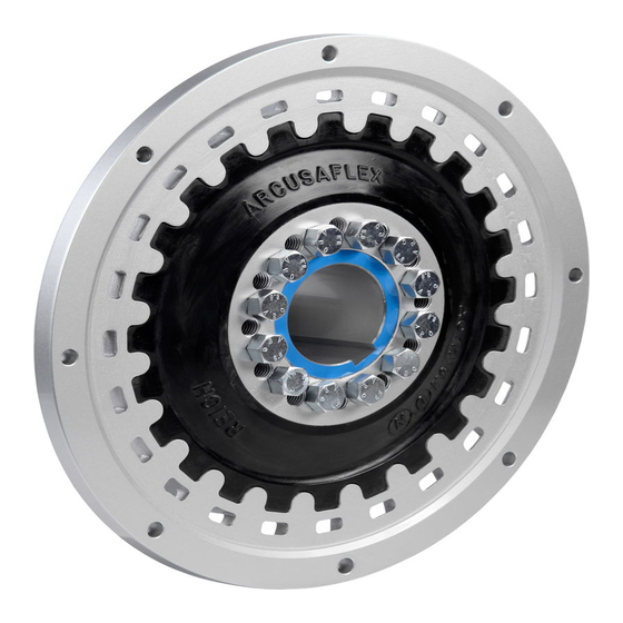
- Page 1 ARCUSAFLEX Highly Flexible Rubber Disc Couplings AC…F2 AC…D F2 AC…F2K AC…D F2K English version of the original German operating instructions 06/2016 - en - 15500000000002...
-
Page 3: Table Of Contents
Contents Notes on the supplementary manual and the manufacturer..... 5 Keeping the instructions available............... 5 Target group of these operating instructions..........5 Copyright ....................6 Related documents .................. 6 Structural features of these operating instructions ........6 Warranty and liability ................. 7 Manufact urer's address ................ - Page 4 Mounting the coupling ................27 Lifting loads during assembly ..............27 Basic instructions for the types AC…F2K and AC…D F2K ......28 Preparing for assembly ................30 Basic notes regarding the conditi o n of deli v ery ...........31 Basic notes regarding the coupling hubs ...........33 Mounting the coupling hub on the shaft.............34 Assembly notes for a hub bore with press fit or transition fit......35 Mounting the coupling element ..............36...
-
Page 5: Notes On The Supplementary Manual And The Manufacturer
Notes on the supplementary manual and the manufacturer Notes on the supplementary manual and the manufacturer These operating instructions help you use the coupling properly and safely. Keeping the instructions available These operating instructions are an integral part of the coupling. Make sure that these operating instructions are constantly available at the place of use and in legible condition for the user. -
Page 6: Copyright
Notes on the supplementary manual and the manufacturer Copyright These operating instructions and all their annexes contain information which is subject to copyright. They must only be used for the operation of the coupling. These operating instructions must not be copied, printed or reproduced, processed, duplicated or disseminated in any way or in any form –... -
Page 7: Warranty And Liability
Notes on the supplementary manual and the manufacturer Warranty and liability Our general commercial terms and conditions apply in general. These can be seen in the Internet at http://www.reich-kupplungen.com. Warranty and liability claims for personal injury and property damage are denied in all cases in which these are attributable to one or more of the following causes: Improper use of the coupling. -
Page 8: Safety
Safety Safety Proper use The ARCUSAFLEX series couplings in the AC…F2, AC…D F2, AC…F2K and AC…D F2K types are used to transmit torques and rotational speeds between a drive unit and the driven machine in the horizontal position. They reduce torsional vibrations and shock loads and are able to compensate for misalignments. -
Page 9: Duties Of The Owner
Safety Duties of the owner The owner of the coupling is bound by laws and regulations to issue instructions which ensure safe operation. The owner must define a “responsible person”. Only this person is authorised to issue a work clearance permit for working on and with the coupling. Work on the coupling described herein must not be executed unless the written work clearance permit for the execution of that work is available from the responsible person. -
Page 10: Duties Of The Personnel
Safety Duties of the personnel The personnel working on and with the coupling must: have read and understood all operating instructions, be familiar with all safety devices and regulations, observe and comply with all safety instructions and warning notices applicable to the place of use, be familiar with and adhere to the basic occupational health and safety regulations and accident prevention regulations. -
Page 11: Note Regarding Residual Dangers
Safety Wear ear protectors in areas in which your hearing may be damaged. Wear a respiratory protector during work when your respiratory system may be damaged. Make sure that the work areas and escape routes are not blocked at the place of use. -
Page 12: Danger To Life Due To Improper Transportation And Handling Of The Coupling
Safety Danger to life due to improper transportation and handling of the coupling If the coupling or its components are inadequately supported during transport, assembly or disassembly, there is a risk of crushing injuries in the event of the coupling or its components falling down. Exclusively use undamaged lifting and lashing gear which is suitable for the load. -
Page 13: Structural Features Of Warning Notices
Safety Structural features of warning notices DANGER Notices containing the word DANGER warn of a dangerous situation which causes death or severe injuries. WARNING Notices containing the word WARNING warn of a dangerous situation which can cause death or severe injuries. -
Page 14: Warning And Instruction Labels
Safety Warning and instruction labels Observe and comply with the warning and instruction labels which are affixed at the place of use of the coupling. Make sure that none of the warning and instruction signs installed at the coupling's operating location are covered over and that they are all clearly legible at all times. Immediately replace any damaged warning and instruction labels. -
Page 15: Description
Description Description The ARCUSAFLEX series couplings in the AC…F2, AC…D F2, AC…F2K and AC…D F2K types are used to transmit torques and rotational speeds between a drive unit and the driven machine in the horizontal position. They reduce torsional vibrations and shock loads and are able to compensate for misalignments. -
Page 16: Overview Of Type Ac
Description Overview of type AC…D F2 This type uses two coupling elements acting in parallel instead of one. It is therefore designed for the transmission of higher torques. Designation Coupling flange Flexible coupling element (with use of through holes) Coupling hub Bolts Washers (for aluminium flanges or where necessary) Spacer ring (optional) not shown, see page 20... -
Page 17: Overview Of Type Ac
Description Overview of type AC…F2K This type enables the flexible coupling element to be replaced without moving the coupled machines. For this purpose, follow the instructions on page 28 and page 55. Designation Coupling flange Flexible coupling element (with use of threaded bores) Coupling hub Bolts Washers (for aluminium flanges or where necessary) -
Page 18: Overview Of Type Ac
Description Overview of type AC…D F2K This type uses two coupling elements acting in parallel instead of one. It is therefore designed for the transmission of higher torques. This type enables the flexible coupling element to be replaced without moving the coupled machines. -
Page 19: Components
Description Components Coupling flange The coupling flange is bolted to the flywheel on the drive side. The holes required for this purpose are provided on the circumference of the coupling flange. Matching washers, if needed, are included in the scope of supply. Unless otherwise agreed, the required bolts must be provided by the customer. -
Page 20: Spacer Ring (Optional)
Description Spacer ring (optional) The spacer ring (6) is an optional component. It is used to adjust the distance between the coupling hub (3) and the flexible coupling element (2). Operating conditions Depending on the rubber mixture of the flexible coupling element, adhere to the following operating conditions: Rubber mixture Ambienttemperature... -
Page 21: Nameplate
Description The identification (1) of the rubber mixture can be found at the place shown in the figure below. Nameplate The nameplate is an adhesive label and affixed to an appropriate place on the coupling. The nameplate contains the following information: Manufacturer's internet address Coupling designation Article no. -
Page 22: Unpacking And Checking The Scope Of Delivery
Unpacking and checking the scope of delivery Unpacking and checking the scope of delivery Unpacking The coupling or its components are delivered in a transport container. Open the transport container. Remove any filler material. Remove the transport protection device. To handle the coupling, follow the instructions on page 23. Checking the supply Check the scope of supply for correctness and completeness against the delivery note. -
Page 23: Transporting The Coupling
Transporting the coupling Transporting the coupling DANGER Risk of explosion when operating the coupling in potentially explosive atmospheres. Risk of explosion with fatal injuries. Exclusively use couplings bearing the corresponding ATEX marking in potentially explosive atmospheres. In this respect, read and follow the additional notes in the supplementary manual for ATEX operation. -
Page 24: Transporting The Coupling Hub With Coupling Element
Transporting the coupling The following figures show examples of how to transport the coupling and its components. Version A shows a general transport situation. Version B shows the transport situation during assembly. Transporting the coupling hub with coupling element Transporting the coupling flange... -
Page 25: Transporting The Coupling Element
Transporting the coupling Transporting the coupling element Transporting the coupling hub and the spacer ring... -
Page 26: Storing The Coupling
Storing the coupling Storing the coupling Store coupling parts for a maximum of three years. Treat metal components with a suitable corrosion inhibitor. Make sure that the following conditions for flexible coupling elements are adhered to during storage: Exclusively store the coupling or its components in a dry and roofed location. Temperature range from +15 °C to +25 °C. -
Page 27: Mounting The Coupling
Mounting the coupling Mounting the coupling DANGER Risk of explosion when operating the coupling in potentially explosive atmospheres. Risk of explosion with fatal injuries. Exclusively use couplings bearing the corresponding ATEX marking in potentially explosive atmospheres. In this respect, read and follow the additional notes in the supplementary manual for ATEX operation. -
Page 28: Basic Instructions For The Types Ac
Mounting the coupling Basic instructions for the types AC…F2K and AC…D These types enable the flexible coupling element to be replaced without moving the coupled machines. The following conditions must be ensured for this purpose: Make sure that the shaft of the driven machine does not protrude from the coupling hub. - Page 29 Mounting the coupling The following conditions can reduce the space to such an extent that radial assembly and removal are not possible: The centring in the engine flywheel is mounted too deeply. The engine housing is protruding. In such a case, use a removable spacer ring (A) with a corresponding width (x). In this case, you must also use correspondingly longer bolts to fasten the coupling hub and coupling element.
-
Page 30: Preparing For Assembly
Mounting the coupling Preparing for assembly Obtain the work clearance permit from the responsible person prior to all work on and with the coupling. Switch the drive unit off. Secure the drive unit to prevent reactivation. Post up a caution sign indicating that work is in progress. Wear the personal protective equipment specified by the owner. -
Page 31: Basic Notes Regarding The Condition Of Delivery
Mounting the coupling Basic notes regarding the condition of delivery The coupling element and the coupling hub can be delivered in the following conditions: Not assembled Pre-assembled Fully assembled The bolts are marked in the pre-assembled and fully assembled condition. Refer to the following table for the corresponding condition: Marking Condition of the bolts... - Page 32 Mounting the coupling In pre-assembled condition, the coupling element and coupling hub are bolted together but not to the required torque. The pre-assembled condition can be recognised by the red tag or adhesive label attached in the factory. CAUTION! Property damage due to improperly fastened bolts. When using a screw locking compound, for example an adhesive, the required torque must be adapted under circumstances.
-
Page 33: Basic Notes Regarding The Coupling Hubs
Mounting the coupling Basic notes regarding the coupling hubs The coupling hub can be supplied as follows upon customer request: Undrilled Pre-drilled With finished bores and keyways When the coupling hub has been ordered in an undrilled or a pre-drilled condition, the corresponding finished bore with keyway must still be produced, or the desired finishing operations must still be made, prior to assembly. -
Page 34: Mounting The Coupling Hub On The Shaft
Mounting the coupling Mounting the coupling hub on the shaft To handle the coupling, follow the instructions on page 23. Proceed as follows to jointly mount the coupling hub and the coupling element on the shaft of the driven machine: Make sure that the connecting surfaces are free of preservative and grease. -
Page 35: Assembly Notes For A Hub Bore With Press Fit Or Transition Fit
Mounting the coupling Assembly notes for a hub bore with press fit or transition If the bore in the coupling hub has a press fit or transition fit, the coupling hub must be heated before mounting on the shaft. To prevent damage to the flexible coupling element, the coupling hub must be removed from the flexible coupling element before heating. -
Page 36: Mounting The Coupling Element
Mounting the coupling Place the heated coupling hub onto the shaft of the driven machine. Make sure that the coupling hub cools uniformly. Quenching is prohibited. Wait until the coupling hub has cooled to hand temperature. When the coupling hub has cooled to hand temperature on the shaft, reconnect the flexible coupling element to the coupling hub. - Page 37 Mounting the coupling Make sure that the connecting surfaces are free of preservative and grease. Mount the coupling element (2) on the coupling hub (3) (A). In case that the coupling hub has been balanced together with the flexible coupling element, this fact is confirmed on the coupling hub and the flexible coupling element with a stamped-in X.
-
Page 38: Type Ac
Mounting the coupling Type AC…D F2 Make sure that the connecting surfaces are free of preservative and grease. Mount the coupling elements (2) on the coupling hub (3) (A). In case that the coupling hub has been balanced together with the flexible coupling elements, this fact is confirmed on the coupling hub and the flexible coupling elements with a stamped-in X. -
Page 39: Type Ac
Mounting the coupling Type AC…F2K Make sure that the connecting surfaces are free of preservative and grease. If a spacer ring is required, place it onto the coupling hub first. Mount the coupling element (2) on the coupling hub (3) (A). In case that the coupling hub has been balanced together with the flexible coupling element, this fact is confirmed on the coupling hub and the flexible coupling element with a stamped-in X. -
Page 40: Type Ac
Mounting the coupling Type AC…D F2K Make sure that the connecting surfaces are free of preservative and grease. If a spacer ring is required, place it onto the coupling hub first. Place the coupling element with the through holes (2b) onto the coupling hub (3) (A). -
Page 41: Mounting The Coupling Flange
Mounting the coupling Mounting the coupling flange To handle the coupling, follow the instructions on page 23. Proceed as follows to mount the coupling flange (1) on the flywheel of the drive unit: Make sure that the connecting surfaces are free of preservative and grease. Lift the coupling flange in a suitable manner. -
Page 42: Mounting The Spacer Ring (Optional)
Mounting the coupling Mounting the spacer ring (optional) The following example figure shows the mounting location of the optional spacer ring (6). The spacer ring is mounted between the coupling hub (3) and the coupling element (2). Torques for tightening bolted connections A cordless screwdriver may be used to screw the bolts in hand-tight. -
Page 43: Torques For The Bolted Connection Of The Coupling Element And The Coupling Hub
Mounting the coupling Torques for the bolted connection of the coupling element and the coupling The following torques are applicable for bolting the coupling hub to the coupling element. They are only applicable for the following conditions: Total friction factor μ= 0.14 Bolt strength grade 8.8 Coupling size 10.2... -
Page 44: Torques For The Bolted Flange Connection
Mounting the coupling Torques for the bolted flange connection The following torques are applicable for bolting the coupling flange to the engine flywheel. They are only applicable for the following conditions: Total friction factor μ= 0.14 Bolt strength grade 8.8 Aluminium flanges must be mounted only with plain washers. -
Page 45: Aligning The Coupling
Mounting the coupling Aligning the coupling CAUTION! Increased rate of wear to the flexible coupling element due to inadequate alignment of the drive unit and the driven machine. When aligning the drive unit and the driven machine, adhere to the values specified for the angular-, radial and axial displacement. - Page 46 Mounting the coupling A larger shaft displacement, for example when switching a drive unit on and off, is permissible for a short time. The maximum permissible angular, radial and axial displacements must not occur all at the same time. The permissible coupling misalignment limits are dependent on multiple factors such as e.g.
-
Page 47: Engaging The Coupling Halves
Mounting the coupling Coupling size Max. permissible Max. permissible Max. permissible angular radial axial displacement displacement displacement α [°] ΔKr [mm] ΔKa [mm] *) ±7 8, 8D ±5 9, 9D ±4 10, 10D ±3 11,7, 11,7D, 11, ±4 11,9, 11D 12, 12D ±3 *) Observe the following note for types AC…F2K and AC…D F2K:... -
Page 48: Mounting The Protection Device
Mounting the coupling Mounting the protection device The owner must equip the coupling with a protection device prior to commissioning. The coupling must be operated exclusively with the protection device mounted. The protection device must satisfy the following minimum requirements and ensure: Protection against contact with rotating parts Protection against parts flying around after any rupture of the coupling Adequate ventilation of the coupling, for example through integrated cooling slots. -
Page 49: Putting The Coupling Into Operation
Putting the coupling into operation Putting the coupling into operation DANGER Risk of explosion when operating the coupling in potentially explosive atmospheres. Risk of explosion with fatal injuries. Exclusively use couplings bearing the corresponding ATEX marking in potentially explosive atmospheres. In this respect, read and follow the additional notes in the supplementary manual for ATEX operation. -
Page 50: Operation
Operation Operation DANGER Risk of explosion when operating the coupling in potentially explosive atmospheres. Risk of explosion with fatal injuries. Exclusively use couplings bearing the corresponding ATEX marking in potentially explosive atmospheres. In this respect, read and follow the additional notes in the supplementary manual for ATEX operation. -
Page 51: Eliminating Malfunctions
Eliminating malfunctions Eliminating malfunctions DANGER Risk of explosion when operating the coupling in potentially explosive atmospheres. Risk of explosion with fatal injuries. Exclusively use couplings bearing the corresponding ATEX marking in potentially explosive atmospheres. In this respect, read and follow the additional notes in the supplementary manual for ATEX operation. -
Page 52: Table Of Malfunctions
Eliminating malfunctions Table of malfunctions Malfunction Cause Remedy Sudden change in the The alignment of the Decommission the system. noise level. coupling has been Identify the reason for this changed. change, for example Sudden occurrence of vibrations. loosened foundation bolts. Make sure that the alignment of the coupling is corrected properly. -
Page 53: Maintaining The Coupling
Maintaining the coupling Maintaining the coupling DANGER Risk of explosion when operating the coupling in potentially explosive atmospheres. Risk of explosion with fatal injuries. Exclusively use couplings bearing the corresponding ATEX marking in potentially explosive atmospheres. In this respect, read and follow the additional notes in the supplementary manual for ATEX operation. -
Page 54: Performing Inspections
Maintaining the coupling Performing inspections The owner has the duty to inspect the coupling at the intervals defined for the specific operation. The inspection must be performed by qualified, specialist personnel and documented thereafter. Visually inspect the coupling on a regular basis, but at least once a year. During the inspection, check for damage of all kinds and particularly for: −... -
Page 55: Replacing The Coupling Elements
Maintaining the coupling Replacing the coupling elements Type AC…F2 and AC…D F2 The following description applies to couplings with one coupling element. Proceed accordingly in the case of couplings with two coupling elements. The coupling elements of these types cannot be replaced without moving the coupled machines. -
Page 56: Completing The Maintenance Work
Maintaining the coupling Mounting the coupling To install, proceed as described in the section entitled from page 27. Make sure that the connecting surfaces are free of preservative and grease. Raise the coupling element in a suitable manner. Insert the spacer ring, if fitted. Fasten the coupling element hand-tight to the coupling hub using the bolts. -
Page 57: Cleaning The Coupling
Cleaning the coupling Cleaning the coupling DANGER Risk of explosion when operating the coupling in potentially explosive atmospheres. Risk of explosion with fatal injuries. Exclusively use couplings bearing the corresponding ATEX marking in potentially explosive atmospheres. In this respect, read and follow the additional notes in the supplementary manual for ATEX operation. -
Page 58: Dismantling The Coupling
Dismantling the coupling Dismantling the coupling DANGER Risk of explosion when operating the coupling in potentially explosive atmospheres. Risk of explosion with fatal injuries. Exclusively use couplings bearing the corresponding ATEX marking in potentially explosive atmospheres. In this respect, read and follow the additional notes in the supplementary manual for ATEX operation. -
Page 59: Disposing Of The Coupling
Disposing of the coupling Disposing of the coupling Dispose of the coupling through a certified specialist disposal company. Observe and comply with the country-specific regulations applicable to the place of use. If in doubt, contact your municipal or local administration. Sort the coupling components according to their materials: Steel Light alloy...
Need help?
Do you have a question about the ARCUSAFLEX AC F2 Series and is the answer not in the manual?
Questions and answers