Advertisement
Quick Links
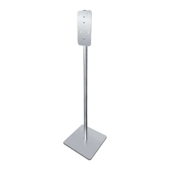
1. ASSEMBLY:
1.1 Lock post to base with one (1) split helical lock washer (supplied) and 5/16" -18 x 1" hex bolt (supplied)
using a 1/2" [13] wrench (by others), as shown on detail A
2.2 Unit should be placed in location to maximize access by pedestrian traffic and to not interfere with any ac-
cessible route clearances.
SPLIT LOCK WASHER
(SUPPLIED)
DETAIL A
2. STEPS TO INSTALL 20364 AND 20365
2.1 Secure dispenser (supplied separately) to the stand mounting plate (factory installed) with four (4) screw-posts
(supplied) through concealed mounting holes in the dispenser back (see Detail B and Detail C)
2.2 Use two (2) #2 Philips bit screw drivers (by others) into binding barrels (supplied) inserted from behind the
mounting plate (see detail C).
2.3 Follow detailed Set-up instructions & provided in dispenser Owner Manual (OM) provided with dispenser.
2.4 When assembly is completed no fasteners are visible on exposed dispenser surfaces.
A
C
POST
BASE
HEX BOLT (SUPPLIED)
1/2" [13] WRENCH
(BY OTHERS)
DISPENSER SUPPLIED SEPARATELY.
B
MODEL N° 20364 DISPENSER SHOWN FOR REF ONLY.
MODEL N° 20365 SIMILAR
PHILIPS SCREW
DRIVER (BY OTHERS)
DETAIL B
PHILIPS SCREW DRIVER
(BY OTHERS)
PHILIPS SCREW
BINDING BARREL AND
DRIVER (BY OTHERS)
SCREW SUPPLIED
LOOSE IN KIT
QTY = 4
BINDING BARREL
AND SCREW
(SUPPLIED)
TYPICAL OF FOUR (4)
BINDING BARREL (SUPPLIED)
TYPICAL OF FOUR (4)
SCREW (SUPPLIED)
TYPICAL OF FOUR (4)
PHILIPS SCREW DRIVER
(BY OTHERS)
DISPENSER SUPPLIED SEPARATELY.
MODEL N° 20364 DISPENSER SHOWN FOR REF ONLY.
MODEL N° 20365 SIMILAR
DETAIL C
043020103520 04APR20
Advertisement

Subscribe to Our Youtube Channel
Related Manuals for ASI FS-0300

Summary of Contents for ASI FS-0300
- Page 1 1. ASSEMBLY: 2. STEPS TO INSTALL 20364 AND 20365 2.1 Secure dispenser (supplied separately) to the stand mounting plate (factory installed) with four (4) screw-posts 1.1 Lock post to base with one (1) split helical lock washer (supplied) and 5/16" -18 x 1" hex bolt (supplied) (supplied) through concealed mounting holes in the dispenser back (see Detail B and Detail C) using a 1/2"...
- Page 2 STEPS TO INSTALL 0361 2.1 Clean dispenser back with Isopropyl Alcohol. Allow to dry completely. 2.2 Cut the 16" double sided tape (supplied) into two (2) lengths of 7-7/8" [200] as shown on diagram. 2.3 Adhere tape strips per diagram with no wrinkles or air bubbles, with liners in place, press to ensure even attachment. 2.4 Clean HSDS mounting plate with Isopropyl Alcohol.
- Page 3 STEPS TO INSTALL 0362 2.1 Clean dispenser back with Isopropyl Alcohol. Allow to dry completely. 2.2 Cut the 16" double sided tape (supplied) into two (2) lengths of 8" [203] as shown on diagram. 2.3 Adhere tape strips per diagram with no wrinkles or air bubbles, with liners in place, press to ensure even attachment. 2.4 Clean HSDS mounting plate with Isopropyl Alcohol.
- Page 4 STEPS TO INSTALL 0501-1 2.1 Clean dispenser back with Isopropyl Alcohol. Allow to dry completely. 2.2 Cut the 16" double sided tape (supplied) into two (2) lengths of 7-7/8" [200] as shown on diagram. 2.3 Adhere tape strips per diagram with no wrinkles or air bubbles, with liners in place, press to ensure even attachment. 2.4 Clean HSDS mounting plate with Isopropyl Alcohol.
Need help?
Do you have a question about the FS-0300 and is the answer not in the manual?
Questions and answers