Table of Contents
Advertisement
Advertisement
Table of Contents

Related Manuals for Ace FMC-75-HYD Series


Summary of Contents for Ace FMC-75-HYD Series
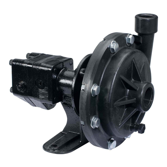
- Page 1 INSTRUCTION MANUAL HYDRAULIC MOTOR DRIVEN CENTRIFUGAL PUMPS...
- Page 2 Ace Pump Corporation shall not be held liable for damages caused by abuse or misuse of the product or parts. No claim for labor in repairing or replacing such products will be allowed nor will loss of time or inconvenience be considered warranty obligations.
- Page 3 HANDLE CHEMICAL PRODUCTS SAFELY Direct exposure to hazardous chemicals may cause serious injury. Potentially hazardous chemicals used with Ace pumps are hydraulic fluid, fertilizer, and chemicals. A Material Safety Data Sheet (MSDS) provides specific details on chemical products: physical and health hazards, safety procedures, and emergency response techniques.
-
Page 4: Plumbing Diagram
A = 10 x hose diameter HYDRAULIC MOTOR FEATURES Coasting Check - This internal feature is standard for all Ace hydraulic motors. It protects the motor seal from pressure spikes created by the flywheel effect of the impeller when the pump is turned off. -
Page 5: Pump Mounting
Consult your tractor dealer for low pressure return options. Do not install any hydraulic components in series downstream from the sprayer pump motor. Consult Ace Product Update 1 - Hydraulic Seals for additional information. - Page 6 The flows out of the hydraulic valves can exceed 29 GPM while the motors are rated at 4 to 11 GPM. The flow limiter protects the Ace motor by shutting off when hydraulic flows exceed the motor’s capacity.
- Page 7 The resulting thermal shock creates radial cracks in the white ceramic face and the heat may melt rubber components. Consult Ace Product Update 2- Mechanical Seals for additional information.
-
Page 8: Pump Repair Kits
Disassembly Steps 1-5 PUMP REPAIR KITS Ace hydraulic pump repair kits include the mechanical seal and volute O-ring. Pumps manufactured after January 1996 use the volute O-ring and have a groove machined in the volute. Older pumps require a gasket volute seal. Note: Do not use both the O-ring and gasket. -
Page 9: Maintenance And Storage
19. Install four 5/16” socket head cap screws and tighten to 15 ft. lb. torque. MAINTENANCE AND STORAGE 1. Ace pumps are equipped with factory lubricated bearings and require no further lubrication. 2. If danger of freezing exists, drain the pump by removing the bottom volute pipe plug. - Page 10 HYDRAULIC MOTOR REPAIR KITS Ace hydraulic motor repair kits include all O-rings and seals necessary to rebuild the motor. The motor model number and date code are stamped on the end plate below the ports. The 200 series kit will fit all motors including those with “L”, “N”, or “R”...
- Page 11 ASSEMBLY: Place drive shaft/bearing assembly in drive plate. Apply a thin film of hydraulic oil to the seal bullet. Insert seal/bullet assembly over shaft tang. Press seal by hand over the installation bullet until the seal casing touches the drive plate. Place a 3/4”...
- Page 12 30%. Typically, the heat added to the system is due to energy losses caused by large bypass flows and restriction. Improper regulation of hydraulic oil to the Ace motor can cause the oil to heat up (refer to pages 4 and 5 for setup instructions).
Need help?
Do you have a question about the FMC-75-HYD Series and is the answer not in the manual?
Questions and answers